1
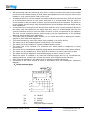
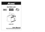
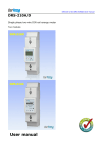
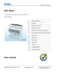
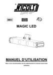
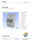
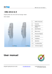
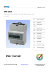
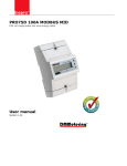
DRT-301C User Manual DRT-301C Three phase four wire DIN rail energy meter with MODBUS protocol Six modular 1.1 Safety instructions 1.2 Foreword 1.3 Performance criteria 1.4 Meter specification 1.5 RS485 communication specification 1.6 Far Infrared communication specification 1.7 Basic errors 1.8 Description 1.9 Dimensions 1.10 Installation 1.11 Operating 1.12 CT Changing-Ratio setting 1.13 Troubleshooting 1.14 Technical support User manual Shanghai fengyilong electronic CO.LTD www.china-meters.com Email:[email protected] 021-62270763/ 62270963 DRT-301C User Manual 1.1 Safety instructions Information for Your Own Safety This manual does not contain all of the safety measures operating the equipment (module, device) for different conditions and requirements. However, it does contain information which you must know for your own safety and to avoid damages. These information are highlighted by a warning triangle indicating the degree of potential danger. Warning This means that failure to observe the instruction can result in death, serious injury or considerable material damage. Caution This means hazard of electric shock and failure to take the necessary safety precautions will result in death, serious injury or considerable material damage. Qualified personnel Operation of the equipment (module, device) described in this manual may only be performed by qualified personnel. Qualified personnel in this manual means person who are authorized to commission, start up, ground and label devices, systems and circuits according to safety and Regulatory standards. Use for the intended purpose The equipment (device, module) may only be used for the application specified in the catalogue and the user manual, and only be connected with devices and components recommended and approved by Forlong. Proper handling The prerequisites for perfect, reliable operation of the product are proper transport, proper storage, installation and proper operation and maintenance. When operating electrical equipment, parts of this equipment automatically carry dangerous voltages. Improper handling can therefore result in serious injuries or material damage. Use only isulating tools. Do not connect while circuit is live (hot). Place the meter only in dry surroundings. Do not mount the meter in an explosive area or expose the meter to dust, mildew and insects. Make sure the wires are suitable for the maximum current of this meter. Make sure the AC wires are connected correctly before activating the current/voltage to the meter. Do not touch the meter connecting clamps directly with metal, blank wire and your bare hands as you may get electrical shock. Make sure the protection cover is placed after installation. Installation, maintenance and reparation should only be done by qualified personnel. Never break the seals and open the front cover as this might influence the function of the meter, and will cause no warranty. Do not drop, or allow strong physical impact on the meter as the high precisely components inside may be damaged. Shanghai fengyilong electronic CO.LTD www.china-meters.com Email:[email protected] 021-62270763/ 62270963 DRT-301C User Manual Disclaimer We have checked the contents of this publication and every effort has been made to ensure that the descriptions are as accurate as possible. However, deviations from the description cannot be completely ruled out, so that no liability can be accepted for any errors contained in the information given. The data in this manual is checked regularly and the necessary corrections are included in subsequent editions. We are grateful for any improvements that you suggest. Subject to technical modifications without notice. Copyright Copyright Forlong July 2008 All rights Reserved. It is prohibited to pass on or copy this document or to use or disclose its contents without our express permission. Any duplication is a violation of the law and subject to criminal and civil penalties. All rights reserved, particularly in the event of a patent award or utility model registration. 1.2 Foreword Thank you for purchasing the Forlong DRT301C DIN rail three phase four wire energy meter with modbus protocol. Output is LCD displayed based on kWh and the data can be transported by isolated RS485 . The meter is provided with a non-volatile memory system that ensures that the readings are not lost or altered when power off. The forlong DRT301C energy meter is the most advanced type electronic kWh meter available at the market. With the Forlong product range we have introduced a large scale of energy meters on the market suitable for 110V AC to 400V AC (50 or 60Hz). Besides the normal energy meters we also developed our own pre-paid meters with chip card, chip card re-loaders and a complete PC management control system. For more information on other product please contact our sales department at [email protected] or [email protected]. Although we produce the Forlong DRT301C meter according to IEC 62053-21 and our quality inspection is very accurate there might always be a possibility that your product shows a fault or failure for which we do apologize. Under normal conditions your product should give you years of benefit and pleasure. In case there is a problem with the energy meter you should contact your dealer immediately. All energy meters are sealed with a special seal. Once this seal is broken there is no possibility to claim for warranty. Therefore NEVER open an energy meter or break the seal of the energy meter. The warranty time is 6 months, after installation, and only valid for construction faults. 1.3 Performance criteria: Operating humidity Storage humidity Operating temperature Storage temperature Shanghai fengyilong electronic CO.LTD ≤ 75% ≤ 95% -10°C - +50°C -30°C - +70°C www.china-meters.com Email:[email protected] 021-62270763/ 62270963 DRT-301C User Manual International standard Accuracy class Protection against penetration of dust and water Insulating encased meter of protective class 1.4 Meter specifications: Meter type Nominal voltage (Un) Operational voltage Insulation capabilities: - AC voltage withstand - Impulse voltage withstand Basic current (Ib): CT type Directly connect Maximum rated current (Imax) CT type Directly connect Operational current range Over current withstand Operational frequency range Internal power consumption Test output flash rate (PULSE LED) CT type Directly connect Test pulse output rate (pins 8 & 9) CT type Directly connect CT Changing-Ratio Power supply indicator (Phase A,B & C LED) Consumption indicator (PULSE & SO LED) Communication indicator Data communication port Data save 1.5 RS485 communication specifications: Bus type protocol baud rate Address range Bus Loading Rage 1.6 IEC 62053-21 1 IP51 Ⅱ DRT-301C (LCD display) 230/400V AC (3~) 161/279 – 300/520V AC (3~) 2KV for 1 minute 6KV – 1.2µS waveform 1.5A 10A 6A 100A 0.4% Ib- Imax 30Imax for 0.01s 50Hz ±10% ≤2W / 10VA per phase 1600imp/kWh 400imp/kWh 1600imp/kWh 400imp/kWh 27 ratios to choose Meter is connected and A/B/C voltage power on Flashing at load running Flashing at communication running RS485 and far infrared The data can be stored more than 20 years when power off RS485 MODBUS RTU with 16 bit CRC 1200(default) 2400,4800,9600,19200(on request) 0-255 user settable 256 meters per bus 1200m Far Infrared communication specifications: infrared wavelengths 900- 1000nm Shanghai fengyilong electronic CO.LTD www.china-meters.com Email:[email protected] 021-62270763/ 62270963 DRT-301C User Manual baud rate communication distance communication angle protocol 1.7 1200bps(default),9600bps(option) 5m -15°~+15° MODBUS RTU with 16 bit CRC Basic errors: With balanced loads 0.05Ib 0.1Ib 0.1Ib - Imax 0.2Ib - Imax Cosφ Cosφ Cosφ Cosφ Cosφ Cosφ = = = = = = 1 0.5L 0.8C 1 0.5L 0.8C ±1.5% ±1.5% ±1.5% ±1.0% ±1.0% ±1.0% Cosφ = 1 Cosφ = 0.5L ±2.0% ±2.0% With single phase load 0.1Ib - Imax 0.2Ib - Imax 1.8 Description A B C D Front panel Cover Base Security hasp Material Front panel Cover Base Shanghai fengyilong electronic CO.LTD PC inflammable retarding ABS inflammable retarding ABS inflammable retarding www.china-meters.com Email:[email protected] 021-62270763/ 62270963 DRT-301C User Manual B A C D 1.9 Dimensions Height Width Depth Weight 1.10 130 mm 126 mm 65 mm 0.7 Kg (net) Installation CAUTION ♦ ♦ Turn off all the power before working on it. Always use a properly rated voltage sensing device to confirm that power is off. WARNING ♦ ♦ ♦ Installation should be performed by qualified personnel familiar with applicable codes and regulations. Use isolated tools to install the meter. Fuse or thermal cut-off or single-pole circuit breaker can’t be fitted on the supply line and not the neutral line. Shanghai fengyilong electronic CO.LTD www.china-meters.com Email:[email protected] 021-62270763/ 62270963 DRT-301C User Manual We recommend that the connecting wire which is used to connect the meter to the outside circuit should be sized according to local codes and regulations for the amp city of the circuit breaker or over current device used in the circuit. An external switch or a circuit-breaker should be installed on the inlet wire, which will be used as a disconnection device for the meter. And there it is recommended that the switch or circuit-breaker is near the meter so that it is more convenience for the operator. The switch or circuit-breaker should comply with the specifications of the buildings electrical design and all local regulations. An external fuse or thermal cut-off which will be used as a over current protection device for the meter must be installed on the supply side wire, and it is recommended that the over current protection device is near the meter so that it is more convenience for the operator. The over current protection device should comply with the specifications of the buildings electrical design and all local regulations. This meter can be installed indoor directly, or in a meter box which is waterproof outdoor, subject to local codes and regulations. To prevent tampering, secure the meter with a padlock or a similar device. The meter has to be installed against a wall which is fire resistant. The meter has to be installed in a good ventilated and dry place. The meter has to be installed in a protection box when placed in dangerous or dusty environment. The meter can be installed and used after being tested and sealed with a letter press printing. The meter can be installed on a 35mm DIN rail or direct on a meter board with screws. The meter should be installed in an available height so that it is easy to read. When the meter is installed in an area with frequent surges due to e.q. thunderstorms, welding machines, inverters etc, protect the meter with Surge Protection Devices After finishing installation, the meter must be sealed to prevent tampering. Connection of the wires should be done in accordance with the underneath connection diagram. A、Direct connect type: so - 485B + 485A 8 9 0 1 1 1 2 1 3 1 4 1 5 1 6 1 7 1 8 1 7 6 5 4 3 2 1 A B C N 1/2 Ia 3/4 5/6 7 8/ 9 Ib IN/OUT Ic IN/OUT Neutral wire Test pulse output contact Shanghai fengyilong electronic CO.LTD IN/OUT www.china-meters.com Email:[email protected] 021-62270763/ 62270963 DRT-301C User Manual 10/11 RS485 communication contact B、CT connect type Ua Ub 485B - 485A N + so Uc 8 9 0 1 1 1 2 1 3 1 4 1 5 1 6 1 7 1 8 1 7 6 5 4 3 2 1 Ia Ib Ic 1/2 3/4 5/6 18/16/14/12 8/ 9 10/11 Ia IN/OUT Ib IN/OUT Ic IN/OUT Phase A/B/C/N Test pulse output contact RS485 communication contact 1.11 Operating Consumption indication On the DRT-301C’S front panel, there are four LED, in which three LED are for three phase voltage and another one for impulse. The constant of the impulse is shown on the nameplate of the meter. Reading the meter The DRT-301C energy meter is equipped with 6+1 or 5+2 LCD display, which is used as recording consumption and can’t be reset to zero. The number system is based on units of 10. And unit is kWh. Another way through RS485 and PC software or HHU(hand held unit)unit can read power consumption Pulse output DRT-301C DIN rail energy meter is equipped with a pulse output which is fully separated from the inside circuit. That generates pulses in proportion to the measured energy. They are test pulse output (pins 8 & 9). Usually, the test pulse output is used as testing accuracy or reading purpose in close quarters. The test pulse output is a polarity dependant, passive transistor output requiring an external voltage source for correct operation. For this external voltage source, the voltage (Ui) should be 5-27V DC, and the maximum input current (Imax) should be 27mA DC. To connect the impulse output, connect 5-27V DC to connector 9 (anode), and the signal wire (S) to connector 8 (cathode). The meter pulses is indicated on the front panel. Communication port DRT301-C has equipped a far infrared port and a RS485 port, we can program the meter’s operation data or reading via these 2 ports. The communication protocol conforms MODBUS RTU Shanghai fengyilong electronic CO.LTD www.china-meters.com Email:[email protected] 021-62270763/ 62270963 DRT-301C User Manual protocol. Far infrared communication port The far infrared communication port is on the left of LCD screen. It is infrared wireless communication port. The TP800 hand-held programmer can directly communicate the data between the meter and this port. The data transmission speed is 1200bps(default),9600(option). The communication distance is not less than 5m. Rs485 output RS485 communication port is between the meter terminal 11 and 10. It is a synchronization wire port. Installing a software in PC, via RS485 adapter Connecting the terminal 11 and 10, PC can communicate with the meter immediately. 1.12 CT Changing-Ratio setting How to set the CT Changing- Ratio of the CT Meter Please set the CT Changing-Ratio after installation otherwise the CT Meter will count the second energy consumption by default Ratio ( 5:5). Procedures of setting the CT Changing- Ratio of the CT Meter: 1. wiring the meter correctly according to Diagram 3 and 4 2. The meter will do auto-detect first when the power is on, and the LCD shows “88888.8.8.” 3. Press the PRG button after auto-detect, then you can set the CT changing- ratio. The LCD shows “-“ 4. Press the SEL button, and there are 27 Ratios (“5:5” to “7500: 5” ) you can choose from. 5. After choosing one CT Changing-Ratio, press the PRG button to confirm and the ration setting is complete. The LCD display “-END”. 6. the meter will back to normal working condition if there is no press on the PRG button in 30s interval, and the LCD shows the first energy consumption and CT Changing-Ratio alternately. NOTE: In the sense of security, setting the CT changing-ratio can only be done in 30s after power on. Any related operation will be null after 30s. 1.13 Troubleshooting CAUTION ♦ ♦ During reparation and maintenance, do not touch the meters connecting clamps directly with your bare hands, with metal, blank wire or other material as you will have the chance of an electricity shock and a possible chance for health damage. Turn off and lock out all power supplying the energy meter and the equipment to which it is installed before opening the protection cover to prevent the hazard of an electric shock. Shanghai fengyilong electronic CO.LTD www.china-meters.com Email:[email protected] 021-62270763/ 62270963 DRT-301C User Manual WARNING ♦ ♦ ♦ Maintenance or reparation should be performed by qualified personnel familiar with applicable codes and regulations. Use insulated tools to maintain or repair the meter. Make sure the protection cover is in place after maintenance or reparation. Problem No light for the Power supply indicator (Phase A, B & C LED). Check Solution Is AC power supply connected to the meter ? Check switch or circuit-breaker and fuse or thermal cut-off. Is the A, B, C and N connecting correct ? Re-install terminal screws on the A, B, C and N. Make sure all screws are fixed. Than there should be a 230V 50Hz AC voltage between the terminal screws on the N and A or B or C, when power supply is input. Is the terminals 1, 2, 3, 4, 5,6 and 7 connecting correct ? Maybe there is a fault in the inside circuit. Is there a power supply inside the meter? No light for the communication indicator(COM.LED) Does any equipment outside communicate with the meter Maybe there is a fault in the inside circuit. Shanghai fengyilong electronic CO.LTD Reinstall terminal screws on the 1, 2, 3, 4, 5,6 and 7. Make sure all screws are fixed. Than there should be a 230V 50Hz AC voltage between the terminal screws on the 7 and 1 or 3 or 5, when power supply is input. Please contact your technical supporter to replace this meter. Check that the power supply Only when the communication between the meter’s infrared port Or the RS485 port and the equipment outside, The LED will blink Please contact your technical supporter to replace this meter. www.china-meters.com Email:[email protected] 021-62270763/ 62270963 DRT-301C User Manual Problem No communication Of RS485 wire data with the meter Check Solution Is the meter ID correct? Check and use the correct the Meter ID. After the meter finish the production, the Meter ID defaults to 0~67H ,69H~FFH . Is the communication distance too long? Shorten the communication distance between the reading equipment outside and the meter. Keep sure it is not more than 1200m The equipment to connection with RS485 main wire is not more than 256pcs Is there too many meters connected to RS485 main wire Is the RS485 port connection correct? Is the connection Maybe there is a fault in the inside circuit. Is the meter ID correct? No communication of the infrared wireless data with the meter Shanghai fengyilong electronic CO.LTD The correct connection is: the A signal wire of RS485 main wire to the meter terminal 11,the B signal wire of RS485 main wire to the meter terminal 10 Please connect with technical supporter to replace this meter. Check and use the correct the Meter ID. After the meter finish the production, the Meter ID defaults to 0~67H ,69H~FFH Is the communication distance too long? Shorten the communication distance between the reading equipment outside and the meter. suggest not more than 5m Is the communication protocol correct? Please contact the technical support to get the meter communication protocol Maybe there is a fault in the inside circuit. Please contact the technical supporter to replace this meter. www.china-meters.com Email:[email protected] 021-62270763/ 62270963 DRT-301C User Manual Problem The LCD energy register can’t run. Check Solution Is the load running ? Only when load is running, RED LED is burning continue, the LCD energy register will run. Is the operating power too low ? If the operating power is too low, the spacing interval of the pulses will take some more time. This is why it seems like the LCD energy register can’t run Maybe there is a fault in the inside circuit. Is DC power supply connected to the meter ? No pulse output. Is the connecting correct ? Maybe there is a fault in the inside circuit. Pulse output rate wrong. Maybe there is a fault in the inside circuit. Please contact your technical supporter to replace this meter. Check the external voltage source (Ui) is 5-27V DC. Check correct connecting: Connect 5-27V DC to connector 3 (anode), and the signal wire (S) to connector 2 (cathode). Please contact your technical supporter to replace this meter. Please connect with technical supporter to replace this meter. 1.14 Technical support Any questions, please contact: TEL: 021-62270763 FAX: 021-62270563 Email: [email protected] www.china-metes.com Forlong Shanghai fengyilong electronic CO.LTD www.china-meters.com 2008 Email:[email protected] 021-62270763/ 62270963