1
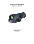
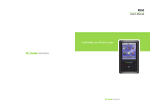
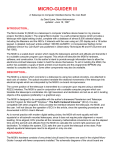
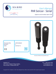
SpecterOS3.0 Optical Sight Operation Manual ARMAMENT TECHNOLOGY INCORPORATED 3045 ROBIE STREET, SUITE 113 HALIFAX NS B3K 4P6 CANADA [email protected] www.armament.com Table of Contents 1. Introduction ………………………………………………………………………….. page 2 2. Installation of battery……………………………………………………………….. page 4 3. Mounting the sight………………………………………………………………….. page 4 4. Illuminating the reticle …………………………………………………………….. page 5 5. Zeroing the SpecterOS3.0…………………………………………………………… page 6 Zeroing the Model ATOS3.0A2…………………………………………. page 6 Model ATOS3.0A2 25 meter ‘rough’ zeroing……………….. page 7 Model ATOS3.0A2 100 meter ‘fine’ zeroing………………… page 8 Zeroing the ATOS3.0B2 ‘Marksman’ model…………………………. Page 9 Model ATOS3.0B2 25 meter ‘rough’ zeroing……………….. page 10 Model ATOS3.0B2 100 meter ‘fine’ zeroing……………….. page 11 6. Using the Model ATOS3.0A2 Reticle……………………………………………… page 12 7. Using the Model ATOS3.0B2 Reticle…………………………………………… page 14 8. Optional Anti-Reflection Device (ARD) ……………………………………….. page 15 9. Maintenance………………………………………………………………………… page 16 SpecterOS3.0 Optical Sight Operation Manual Page 1 1. Introduction The SpecterOS3.0 Optical Sight is a 3x magnified optical aiming device for small arms. Its principle of operation is to display an etched reticle over a magnified image of the target to act as an aiming point. The SpecterOS3.0 attaches promptly to Mil-Std-1913 ‘Picatinny Rail’ receivers and mounts, and may be removed and re-attached without noticeable loss of zero. Because the SpecterOS3.0 is a primarily an optical-mechanical device, it is always provides an aiming reticle even in the case of loss of electrical power due to battery failure or EMP. In low light conditions, the SpecterOS3.0 reticle may be illuminated by a high efficiency LED that is powered by one user-installed CR123 Lithium battery. The brightness of the reticle illumination is adjustable to be visible through a broad range of ambient light conditions, including several settings designed for viewing either in front of or behind night vision devices. The SpecterOS3.0 is fitted with rubber bumpers that are designed to protect the sight from impacts as well as to protect the zeroing adjustments. Figure 1 SpecterOS3.0 Optical Sight Operation Manual Page 2 Figure 2 The SpecterOS3.0 is available in two configurations: 1) Model ATOS3.0A2: SpecterOS3.0 ‘basic’ model with ‘set and forget’ elevation and windage zeroing adjustments and ballistic aiming corrections within the reticle. The reticle incorporates the proprietary Rapid Aiming Feature as well as a Vertical Subtention Optical Rangefinder (VSOR). Once the sight is zeroed, typically the caps are replaced and users are required to aim off to compensate for wind or range variations. Figure 3 2) Model ATOS3.0B2: SpecterOS3.0 ‘Marksman’s’ model with external elevation and windage adjustments. Because it has a bullet drop compensator on the elevation knob, model ATOS3.0B2 has no ballistic data within the reticle. The reticle does incorporate the proprietary Rapid Aiming Feature as well as a Vertical Subtention Optical Rangefinder. Users may make rapid adjustments to compensate for wind or range variations. Figure 4 Figure 3 SpecterOS3.0 Optical Sight Operation Manual Figure 4 Page 3 2. Installation of battery To install the battery, first locate the battery cap at the front end of the battery tube. Figure 5 Remove the battery cap by rotating it counter-clockwise until it separates fully from the battery tube. Install the CR123 Lithium battery, positive (+) end first, into the battery tube and replace cap. Be careful not to cross-thread the battery cap when re-installing it. Tighten the battery cap with moderate finger pressure. Do not over-tighten. Figure 5 3. Mounting the sight Mounting the SpecterOS3.0 is simple. 1. WITH MUZZLE POINTING IN A SAFE DIRECTION, INSURE THE FIREARM IS UNLOADED! 2. Turn the wing nut in the clamp base of the sight counter-clockwise to loosen the clamp foot fully. The wing nut is captive to the shaft and will come to a natural stop when loosened fully. Do not try to loosen beyond the point where the wing nut stops turning freely, as this will cause damage to the wing nut. 3. Select a position on the weapon receiver to mount the sight. The SpecterOS3.0 has an eye relief 0f 68mm and therefore must be mounted at a position that gives the user a full field of view. The recoil cross bar in the sight base must line up with a corresponding slot in the receiver or mount rail. 4. Once the best position is selected, and the crossbar is seated in the desired cross-slot on the weapon receiver, push the sight gently forward so the recoil cross bar rests against the forward edge of the slot. 5. When you are sure that the sight is seated and positioned correctly, tighten the wing nut with moderate finger pressure. Do not over-tighten and DO NOT USE TOOLS to tighten the wing nut. Figure 6 SpecterOS3.0 Optical Sight Operation Manual Page 4 Figure 6 4. Illuminating the reticle Under all conditions the SpecterOS3.0 displays a reticle within the user’s field of view. To activate illumination of the reticle, rotate the illumination switch clockwise. The SpecterOS3.0 has 14 illumination settings, although the first four or five settings are designed to work with Night Vision (NV) and are not readily seen by the naked eye. As the user rotates the illumination switch clockwise through a series of clicks, the intensity of the reticle illumination will correspondingly increase. The goal is to use a setting that produces a well-defined reticle that produces sufficient contrast against the target. This will be influenced by light conditions as well as by the preference of the user. To switch the unit off, rotate the illumination knob counter-clockwise fully until the stop is reached. Figure 7 Figure 7 SpecterOS3.0 Optical Sight Operation Manual Page 5 5. Zeroing Zeroing the SpecterOS3.0 is a process whereby the sight is adjusted to have the center of the reticle coincidental with the Point Of Impact (POI) at a chosen distance. For general use, the distance chosen by most users is 100 meters. To insure the sight is close to its required zero, it is often easier to begin at 25 meters. This will increase the chances that the first shots will be on the target. Once a 25m zero is achieved, the user may move to 100 meters to quickly achieve a zero at that range. Before you start... The quality of the results of the zeroing process is dependent upon the ability to shoot good and consistent groups. Therefore, the following recommendations are made: Use a stable shooting position. Shooting from the bench is best, however the prone position on the ground is also good. It is not recommended to zero from the standing or kneeling positions. Use a rest to steady your firearm while shooting. A bench rest or sand bag works well. If supporting the forearm of the weapon, try to place the support as close to the receiver as possible. Resting the barrel only, especially close to the muzzle will invariably result in an incorrect point of impact. Have enough ammunition ready to reliably complete the task. Use the same type of ammunition that you intend to commonly use with that firearm. Have a fresh target with a good quality aiming mark. The aiming mark should be such that it helps you consistently aim for the center. A good 100 meter aiming mark might be a black box with a 100-125mm (4-5 inch) white square in the center. Fire three-round groups and make adjustments from the center of the group. This will demonstrate the accuracy potential of the firearm/ammunition/marksman combination and will allow you to make adjustments based on your average results. A tape measure will allow you to accurately determine the corrections required to center your group about the aiming mark. A spotting scope will save a certain amount of back-and-forth travel to the target. Target pasters or masking tape will allow you to cover up previous groups to avoid confusion. Begin at 25 meters to get a ‘rough’ zero. This will reduce the chances that you will be ‘off the paper’ with your initial shots. When you are close to the aiming mark at 25 meters, move to 100 meters to fine-tune the adjustment. Zeroing the SpecterOS3.0 Model ATOS3.0A2 Principle The SpecterOS3.0 is designed to be zeroed (sighted-in) at a range of 100 meters. Once the sight is zeroed at 100 meters, targets at 300 to 800 meters may be engaged by aiming with the appropriate range lines marked on the vertical stadia of the reticle. Once zeroed for windage in the sight-in process, the user may compensate for subsequent wind conditions by “aiming off” (compensating by aiming toward the windward side of the target center). SpecterOS3.0 Optical Sight Operation Manual Page 6 Zeroing adjustments The SpecterOS3.0 has adjustments for both windage (left-right) and elevation (up-down). The purpose of these adjustments are to cause the point of aim to coincide with the average point of impact of the bullets at 100 meters. The zeroing adjustments are made with a screwdriver or coin, and each ‘click’ of adjustment equals 1/2 Minute of Angle (MOA) change to the effective point of impact. At 100 meters, this 1/2 MOA click value equals about 14.5mm (about 1/2 inch at 100 yards). Because this is an angular measurement, the change to the point of impact is proportional to the range to the target. Thus, a 1/2 MOA adjustment results in about one inch at 200yards, about an inch-and-a-half at 300 yards, and about 1/8 inch at 25 yards. Model ATOS3.0A2 25 meter ‘rough’ zeroing 1. Remove the caps covering the windage and elevation adjustments (put them in your pocket for safe keeping). 2. Using the most stable shooting platform and position you can, fire a three-shot group at the target. 3. Determine the center of the group. Measure or estimate both the horizontal and vertical distances from the group center to the center of the aiming point. Calculate the number of clicks needed to center the group in both elevation and windage. Remember that at 25 meters, each ‘click’ results in about 1/8 inch point of impact change on the target. For instance, if at 25 meters the group is 4 inches high, then approximately 32 clicks will be required to adjust the point of impact downward. 4. Make the appropriate adjustments to the optical sight. For elevation: If the group is high, turn the elevation adjustment screw clockwise to effectively move the point of Impact lower. If the center of the group is low, turn the elevation adjustment screw counterclockwise to effectively move the point of impact higher. Clockwise moves the point of impact Down Counter-Clockwise moves the point of impact Up. See Figure 8. Figure 8 Figure 8 SpecterOS3.0 Optical Sight Operation Manual Page 7 For windage: If the group is right, turn the elevation adjustment screw clockwise to effectively move the point of Impact left. If the center of the group is left, turn the elevation adjustment screw counter-clockwise to effectively move the point of impact right. Clockwise moves the point of impact Left Counter-Clockwise moves the point of impact Right. See Figure 9. Figure 9 5. After initial adjustments are made, fire another three-round group to verify. If the point of impact is within 25-50mm (one or two inches) of the aiming mark, proceed to 100 meter zeroing. If not, adjust and shoot another group. A rifle that is perfectly sighted at 100 meters will shoot slightly low at 25 meters as a result of the mounting height of the optical sight. Remember that this is intended to be a rough zero only, however a sight that is in good alignment for windage and about 25mm (1 inch) low at 25 meters would be very close to having correct adjustment at 100 meters. Model ATOS3.0A2 100 meter ‘fine’ zeroing 1. Using the most stable shooting platform and position you can, fire a three-shot group at the target. 2. Determine the center of the group. Measure or estimate both the horizontal and vertical distances from the group center to the center of the aiming point. Calculate the number of clicks needed to center the group in both elevation and windage. Remember that at 100 meters, each ‘click’ results in 14.5mm (about 1/2 inch) point of impact change on the target. For instance, if at 100 meters the group is 150mm (6 inches) high, then 12 clicks will be required to adjust the point of impact downward. 3. Make the appropriate adjustments to the optical sight. SpecterOS3.0 Optical Sight Operation Manual Page 8 For elevation: If the group is high, turn the elevation adjustment screw clockwise to effectively move the point of Impact lower. If the center of the group is low, turn the elevation adjustment screw Counterclockwise to effectively move the point of impact higher. Clockwise moves the point of impact Down Counter-Clockwise moves the point of impact Up. See Figure 8. For windage: If the group is right, turn the elevation adjustment screw clockwise to effectively move the point of Impact left. If the center of the group is left, turn the elevation adjustment screw Counterclockwise to effectively move the point of impact right. Clockwise moves the point of impact Left Counter-Clockwise moves the point of impact Right. See Figure 9. 4. After initial adjustments are made, fire another three-round group to verify. Adjust and repeat as necessary. When the desired results are achieved, replace the windage and elevation adjustment caps. Zeroing the SpecterOS3.0 Model ATOS3.0B2 ‘Marksman’ model Principle The SpecterOS3.0 model ATOS3.0B2 is designed to be zeroed (sighted-in) at a range of 100 meters. Once the sight is zeroed at 100 meters, targets at 200 to 600 meters may be engaged by adjusting the elevation assembly to the appropriate range settings marked on the elevation knob. Once zeroed for elevation, additional fine elevation adjustments may be made by adding or subtracting additional 1/2 MoA ‘clicks’ of the elevation knob. Once zeroed for windage in the sight-in process, the user may compensate for subsequent wind conditions by adjusting the windage knob to match the prevailing wind conditions. ‘Marksman’ model ATOS3.0B2 zeroing adjustments The SpecterOS3.0 model ATOS3.0B2 has adjustments for both windage (left-right) and elevation (updown). The purpose of these adjustments are to cause the point of aim to coincide with the average point of impact of the bullets at the chosen range. The zeroing adjustments are made turning the knobs with the fingers, and each ‘click’ of adjustment equals 1/2 Minute of Angle (MOA) change to the effective point of impact. At 100 meters, this 1/2 MOA click value equals about 14.5mm (about 1/2 inch at 100 yards). Because this is an angular measurement, the change to the point of impact is proportional to the range to the target. Thus, a 1/2 MOA adjustment results in about one inch at 200 yards, about an inch-and-a-half at 300 yards, and about 1/8 inch at 25 yards. Because the ATOS3.0B ‘Marksman’ model has elevation and windage knobs that are limited to one full turn, it may be necessary to remove the calibrated knobs completely until the zeroing process is fully completed at 100 meters. This may be accomplished with the enclosed 5/64 Allen wrench. Figure 10 SpecterOS3.0 Optical Sight Operation Manual Page 9 Figure 10 Marksman’ model ATOS3.0B2 25 meter ‘rough’ zeroing 1. Remove the external elevation and windage knobs. This may be done by loosening the two set screws in each knob using the supplied 5/64 Allen wrench. It is not necessary or desirable to remove the set screws completely. Just turn them two turns counterclockwise to disengage them from the groove in the inner shaft. Once the knobs are removed, put them in your pocket for safe keeping. 2. Using the most stable shooting platform and position you can, fire a three-shot group at the target. 3. Determine the center of the group. Measure or estimate both the horizontal and vertical distances from the group center to the center of the aiming point. Calculate the number of clicks needed to center the group in both elevation and windage. Remember that at 25 meters, each ‘click’ results in 3.6mm (about 1/8 inch) point of impact change on the target. For instance, if at 25 meters the group is 100mm (4 inches) high, then approximately 32 clicks will be required to adjust the point of impact downward. 4. Make the appropriate adjustments to the optical sight. For elevation: If the group is high, turn the elevation adjustment shaft clockwise to effectively move the point of Impact lower. If the center of the group is low, turn the elevation adjustment shaft Counterclockwise to effectively move the point of impact higher. Clockwise moves the point of impact Down Counter-Clockwise moves the point of impact Up For windage: If the group is right, turn the elevation adjustment shaft clockwise to effectively move the point of Impact left. If the center of the group is left, turn the elevation adjustment shaft counterclockwise to effectively move the point of impact right. Clockwise moves the point of impact Left Counter-Clockwise moves the point of impact Right SpecterOS3.0 Optical Sight Operation Manual Page 10 5. After initial adjustments are made, fire another three-round group to verify. If the point of impact is within 25-50mm (one or two inches) of the aiming mark, proceed to 100 meter zeroing. If not, adjust and shoot another group. A rifle that is perfectly sighted at 100 meters will shoot slightly low at 25 meters as a result of the mounting height of the optical sight. Remember that this is intended to be a rough zero only, however a sight that is in good alignment for windage and about 25mm (1 inch) low at 25 meters would be very close to having correct adjustment at 100 meters. ‘Marksman’ model ATOS3.0B2 100 meter ‘fine’ zeroing 1. Using the most stable shooting platform and position you can, fire a three-shot group at the target. 2. Determine the center of the group. Measure or estimate both the horizontal and vertical distances from the group center to the center of the aiming point. Calculate the number of clicks needed to center the group in both elevation and windage. Remember that at 100 meters, each ‘click’ results in 14.5 (about 1/2 inch) point of impact change on the target. For instance, if at 100 meters the group is 150mm (6 inches) high, then 12 clicks will be required to adjust the point of impact downward. 3. Make the appropriate adjustments to the optical sight. For elevation: If the group is high, turn the elevation adjustment screw clockwise to effectively move the point of Impact lower. If the center of the group is low, turn the elevation adjustment screw Counterclockwise to effectively move the point of impact higher. Clockwise moves the point of impact Down Counter-Clockwise moves the point of impact Up For windage: If the group is right, turn the elevation adjustment screw clockwise to effectively move the point of Impact left. If the center of the group is left, turn the elevation adjustment screw counter-clockwise to effectively move the point of impact right. Clockwise moves the point of impact Left Counter-Clockwise moves the point of impact Right 4. After initial adjustments are made, fire another three-round group to verify. Adjust and repeat as necessary. Once the sight is satisfactorily zeroed, re-install the internal adjustment knobs. Re-installing the Elevation Knob: Place the Elevation knob on the vertical shaft and rotate it until the “1” is aligned with the index mark. Using the 5/64 Allen wrench, tighten both setscrews. Do not use excessive force, just enough to lock the knob to the shaft. Re-installing the Windage Knob: Place the Windage knob on the horizontal shaft and rotate it until the “0” is aligned with the index mark. Using the 5/64 Allen wrench, tighten both setscrews. Do not use excessive force, just enough to lock the knob to the shaft. SpecterOS3.0 Optical Sight Operation Manual Page 11 6. Using the model ATOS3.0A2 Reticle The ATOS3.0A2 reticle has a number of features designed to assist the marksman in determining and compensating for range to the target. Figure 11 Figure 11 Rapid Aiming Feature: The Rapid Aiming Feature is designed to offer a very prominent and distinct aiming mark at close ranges while at not inhibiting precision aiming at long ranges. The horizontal distance between the Rapid Aiming Feature points is 406mm (16 inches) at 100 meters. For military use, this translates to the average distance between the armpits of a standing individual at 100 meters. Figure 12. CAUTION: In non-Military or non-Police use the Optical Sight should NEVER be aimed at another individual! Figure 12 SpecterOS3.0 Optical Sight Operation Manual Page 12 VSOR rangefinder: The Vertical Subtention Optical Rangefinder (VSOR) is designed as an aid to the marksman in determining the range to target. By determining the best fit an object of known height within the lines of the rangefinder, the marksman can determine the range to that object. The SpecterOS3.0 rangefinder is calibrated for a 76mm (30 inch) object. For military use, this translates to the distance from the waist to the top of the head of a standing individual. Figure 13 CAUTION: In non-Military or non-Police use the Optical Sight should NEVER be aimed at another individual! Figure 13 Ballistic rangefinder: The ballistic aiming features of the ATOS3.0A2 reticle are designed to subtend 48cm (19 inches) at the corresponding range. For instance, the width of the horizontal line designating the 400m ballistic aiming mark represents 48cm (19 inches) on the target at 400 meters. For military use, this translates to the average width of the shoulders of a standing individual. Figure 14 CAUTION: In non-Military or non-Police use the Optical Sight should NEVER be aimed at another individual! Figure 14 SpecterOS3.0 Optical Sight Operation Manual Page 13 7. Using the ‘Marksman’ model ATOS3.0B2 Reticle The ATOS3.0B2 reticle has a number of features designed to assist the marksman in determining and compensating for range to the target. Figure 15 Figure 15 Rapid Aiming Feature: The Rapid Aiming Feature is designed to offer a very prominent and distinct aiming mark at close ranges while at not inhibiting precision aiming at long ranges. The horizontal distance between the Rapid Aiming Feature points is 40cm (16 inches) at 100 meters. For military use, this translates to the average distance between the armpits of a standing individual at 100 meters. Figure 16. CAUTION: In non-Military or non-Police use the Optical Sight should NEVER be aimed at another individual! Figure 16 SpecterOS3.0 Optical Sight Operation Manual Page 14 VSOR rangefinder: The Vertical Subtention Optical Rangefinder (VSOR) is designed as an aid to the marksman in determining the range to target. By determining the best fit an object of known height within the lines of the rangefinder, the marksman can determine the range to that object. The SpecterOS3.0 rangefinder is calibrated for a 76mm (30 inch) object. For military use, this translates to the distance from the waist to the top of the head of a standing individual. Figure 17 CAUTION: In non-Military or non-Police use the Optical Sight should NEVER be aimed at another individual! Figure 17 8. Optional Anti-Reflection Device (ARD) The SpecterOS3.0 may be fitted with an optional Anti-Reflection Device (ARD), also known as an SRD (Signature Reduction Device). The purpose of this device is to reduce the incidence of light reflection from the front lens. The ARD is screwed into the threaded ring at the front of the sight, and prevents light from reflecting off the lens at wide angles. When the ARD is installed, the user may notice a slight reduction in sight picture brightness. This is an unavoidable consequence of using the ARD. Figure 18 Figure 18 SpecterOS3.0 Optical Sight Operation Manual Page 15 9. Maintenance The SpecterOS3.0 requires very little user maintenance. Lens Cleaning Lenses may be cleaned with lens paper or any soft, clean, lint-free cloth. Caked-on mud may be first washed away with cold clean water. Do not rub lenses if there is the presence of mud, as this will result in abrasion of the lens coatings and surfaces. Battery The battery should be examined periodically for leakage or corrosion and should be removed from the sight for long-term storage. Optional Anti-reflection Device (ARD) The optional Anti-Reflection Device (ARD) may be cleaned by first removing it from the sight and then holding the device under running water. ARMAMENT TECHNOLOGY INCORPORATED 3045 ROBIE STREET, SUITE 113 HALIFAX NS B3K 4P6 CANADA [email protected] www.armament.com Proprietary Notice This document contains information that is proprietary to Armament Technology Incorporated. This information remains the property of the Company and shall not be reproduced, used or disclosed in any manner or for any purpose not authorized in writing by the Company. SpecterOS3.0 Optical Sight Operation Manual Page 16