1
•
•
•
!
•
"#$%
# &
'
•
()*+,-./
#
$0
•
1
,
'
23(
•
'#40$$0##
•
2
56
62 178
62 178
SMC-VIP04/08 PBX VoIP Gateway User's Manual
SMC TigerAccess VoIP
SMC-VIP04 AND SMC-VIP08
PBX VoIP Gateway
User Manual
Edition 1.0
Page 2/81
PN: 61100000050B
SMC-VIP04/08 PBX VoIP Gateway User's Manual
Table of Contents
! "
!
"#$!
%
%&' (
)&*$* +
),$*-
#. ' #
$
%$
/0
1
% '$
11
%12
/$
! 1
%2
$
$
! 1
%% /$
! 1
%) $
$
! 13
%4
/$
! +
Page 3/81
PN: 61100000050B
SMC-VIP04/08 PBX VoIP Gateway User's Manual
%(4
$
$
! %3$
/$
! %+$
$
$
! 1
%"#
! /$
! %"#
! $
$
! %12
/$
!54-!'0 6$+*4#'0 6$+(7 )
%2
$
! %% */$
!54!'0 6$+(8'0 6$+7 (
%) * $
! 3
%/$
! %+
%( $
! %+
%32'
!/$
! %
%+2'
! $
! %
%'
%
%2
%%
%1 %
%'
! )+
%%/0
)
%% )%
%) )(
%
)#
2
) $ 1
%
#
%
&
Page 4/81
PN: 61100000050B
SMC-VIP04/08 PBX VoIP Gateway User's Manual
"
' "
Page 5/81
PN: 61100000050B
SMC-VIP04/08 PBX VoIP Gateway User's Manual
1 SMC TigerAccess VoIP
The progression towards a converged network continues to push network administrators,
vendors and corporations to better understand what convergence is and how it
ultimately affects the user of such services. In a converged network the user uses the
same tools even while voice communications is added to the IP network. This ensures
familiarity, ease of use and a pleasing experience for the end-user.
SMC Networks, Inc., an industry leader in networking products, has created a
comprehensive line of Voice over Internet Protocol products designed to: a) Provide the
highest quality and experience in the VoIP market: b) Create a quick return on
Investment (ROI) for corporations and other integrators.
SMC’s TigerAccess VoIP class of products are designed for the small-to-medium or
small-to-enterprise businesses. Featuring units with 1U rackmount or desktop designs
make it easy for LAN designers to included them in the network. A plethora of
management and configuration methods are available including Web-based, Telnet or
Console management. Moreover, featuring patented firmware we ensure standardsbased interoperability. SMC knows you’ll enjoy your new VoIP infrastructure.
Thank you for purchasing SMC’s TigerAccess VoIP products and please call us at 1800-SMC-4YOU for both Service and Support.
Sincerely,
SMC Networks, Inc.
Page 6/81
PN: 61100000050B
SMC-VIP04/08 PBX VoIP Gateway User's Manual
2 Before installing this product
This guide will explain how to configure the PBX VoIP gateway using the system
console commands and web management interface. We strongly suggest installation
candidates have technical networking background and PBX VoIP gateway experience.
They must also have knowledge the fundamentals of VOIP.
2.1 Why PBX VoIP Gateway?
2.1.1 Eliminate the b arrier of a heterogeneous
PBX system
Multi-national enterprises with offices located in various national or international sites,
find it hard to have a single PBX system for the whole group of offices. Demands on
departmental services between offices, the size of some offices and various
telecommunication regulations in different countries, make it difficult to use the same
PBX system or even compatible PBX systems.
The SMC PBX VoIP gateway is designed to functions as the PBX tie trunk but
interoperable with different PBX or KTS system.
2.1.2 Toll-Bypass ad vantage
The SMC PBX VoIP gateway utilizes modern VoIP technology so one can have the
toll-bypass advantage with flat rated data access fee. This helps save enormous
expanse especially for large amount of communication hours between offices.
Page 7/81
PN: 61100000050B
SMC-VIP04/08 PBX VoIP Gateway User's Manual
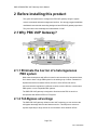
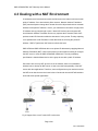
3 Using the PBX VoIP gateway
3.1 Internal Calls
The SMC TigerAccess VoIP (SMC-VIP04 and SMC-VIP08) gateway is designed to be
the tie trunk of your PBX. When two or more PBXs are tied with the SMC VoIP gateway,
the extension line on the remote PBX will perform as an extension of the local PBX
(acting as if both locations were on a single PBX). The following example demonstrates
how a user at the extension on the PBX VoIP gateway with prefix code "2" can dial "9"
plus "*7209" to connect to extension 209 of the PBX that has PBX VoIP gateway with
prefix "7".
Page 8/81
PN: 61100000050B
SMC-VIP04/08 PBX VoIP Gateway User's Manual
4 Quick Installation
4.1 Quick Start
1.
Plug in the Ethernet Cable, Null Modem cable and power on the device to begin
the configuration.
2.
Configure the IP Address, subnet mask, Default Gateway to make the device
reachable from the network.
3.
Configure the prefix of the device
4.
Decide the role (Master or Slave) of the device and configure the Group ID
5.
Add the MAC address of the Slave that are going to joint the group to Master.
6.
Configure the IP address of Master gateway to Slave device
7.
Restart the device to make the configuration take effect.
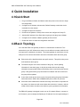
4.2 Basic Topology
Your new SMC PBX VoIP gateway is based on a master/slave architecture. This
means that in your VoIP infrastructure setup, one unit will be the master, while the rest
in the group are considered to be slaves. The master gateway is central since it is the
focal point of all common information and control information within the same group.
Each device will be identified with its own prefix number. This prefix is then put as
an ID within the whole group.
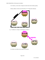
The master keeps a list of all the members of the group. While updating
information for the whole group, it will poll each slave devices with routing
information and group table. Base on this facility, when a new device joints into the
group. It will get the whole group information from Master and other members in
the group will be updated.
A new slave needs to joint into the group via synchronizing the group information
with master device. Before that, it cannot make phone calls to any devices.
Since each slave maintains the member list locally, if the master is inoperable for
any reason, the slaves can still communicate with each other. However, until the
master is back online, the slaves are unable to get any updated new information.
The PBX VoIP gateway is designed to work over an IP network. Before it connects to
an IP network, you must assign the Gateway an IP address. Like the regular settings of
Page 9/81
PN: 61100000050B
SMC-VIP04/08 PBX VoIP Gateway User's Manual
an IP network, you also need to configure the subnet mask and the default gateway.
Defining a Master or Slave device begins after you’ve configured IP addresses.
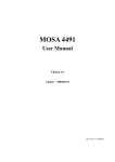
Fig 1 The Master is in charge of maintaining the member list
Fig 2 When a new Slave device registrar into the group
Page 10/81
PN: 61100000050B
SMC-VIP04/08 PBX VoIP Gateway User's Manual
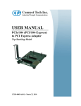
Fig 3 The Master updates the new member list and send it to every member
Fig 4 The Master will synchronize the member information with each members.
Fig 5 The Master will synchronize the member information with each members.
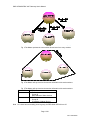
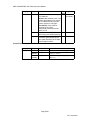
Device Role
Master
Slave
MUST Parameters
Prefix
Group ID
MAC address of Slave devices
Prefix
Group ID
IP address of Master Device
Note 1 If a slave has successfully joined a group, the RED Alarm LED will turn off.
Page 11/81
PN: 61100000050B
SMC-VIP04/08 PBX VoIP Gateway User's Manual
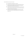
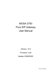
4.3 Dealing with a NAT Environment
IP addresses are a limited resource and not all devices on the Internet can have its own
public IP address. So to deal with this finite resource, Network Address Translation
(NAT) was developed to change the IP header from the LAN packed back into a header
address for the public IP address. Hence, your LAN devices can share a single public
IP address as they pass through a router. Most VoIP devices cannot support NAT,
since Network Address Translation Server only replaces the IP headers, while VoIP
packets contain IP information within the data area of voice packet. Thereby replacing
voice packets with a real IP header, but the data inside is still using the private IP
address. SMC’s TigerAccess VoIP however solves this issue.
SMC-VIP04 and SMC-VIP08 are able to use private IP addresses by applying Network
Address Translation (NAT). Most of the time this is done without needing to configure
the NAT server or even the SMC-VIP04/SMC-VIP08 itself. The only mandatory
specification is that the Master device in the group be set with a public IP address.
Since there are so many NAT servers now in the markets, there is no standard to
address how to develop an NAT server or how to test the interoperability of the NAT
server with other applications. Therefore, some configuration may be needed to ensure
the NAT server has the correct In-bound rules or Out-bound rules so NAT will be able to
work with some special applications.
Fig 6 Support Voice over IP under NAT environment
Page 12/81
PN: 61100000050B
SMC-VIP04/08 PBX VoIP Gateway User's Manual
Only guaranteed for Tested NAT server or software
Some NAT devices must specify the In-bound and Out-bound rules, but some of
them do not need any configuration on NAT server, such as SMC’s Barricade
The Master VoIP device must have a public IP address
Only one Slave device is allowed to be installed on one NAT domain with a private
IP address, that means cascading the units to increase the density of channels by
using private IP address will not be supported.
Some In-bound or Out-bound address translation rules may time out on NAT
server. So user may need to restart the TigerAccess VoIP voice gateway if that
situation occurs.
Page 13/81
PN: 61100000050B
SMC-VIP04/08 PBX VoIP Gateway User's Manual
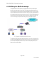
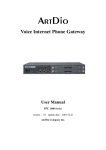
4.4 Utilizing the QoS advantage
The TigerAccess VoIP voice gateway is equipped with QoS. This provides higher
priority for voice than data over your LAN. To fully utilize this advanced feature, you
need to install the device according to the following diagram to have voice sent out with
a superior QoS than data from local area network. You can see the "To WAN" Ethernet
port on the front panel is used to connect to the router. The "To LAN" Ethernet port that
near RS-232 port on the front panel is used to connect to a Switch on the LAN. Thus
voice can have higher priority than data when going out your WAN connection.
Fig 7 Diagram of utilizing Embedded QoS function
To maintain the QoS function while stacking the devices, you need to connect the LAN
port of the primary PBX gateway (that connect to the router in Fig. 2) to the WAN port of
the secondary PBX gateway. And the LAN port the secondary PBX gateway to the
Switch on the local area network.
Page 14/81
PN: 61100000050B
SMC-VIP04/08 PBX VoIP Gateway User's Manual
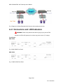
Fig 8 Diagram of utilizing Embedded QoS function while stacking the devices
4.4.1 Connectors an d LED Indicators
WARNING: Please verify that the lines that are going to plug into the FXS
interfaces on PBX VoIP gateway do not have any power source ("0" voltage).
Front Panels
SMC-VIP08
Fig 9 SMC-VIP08 Front Panel
SMC-VIP04
Fig 10 SMC-VIP04 Front Panel
Page 15/81
PN: 61100000050B
SMC-VIP04/08 PBX VoIP Gateway User's Manual
Rear Panels
SMC-VIP08
Fig 11 SMC-VIP08 Rear Panel
SMC-VIP04
Fig 12 SMC-VIP04 Rear Panel
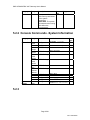
Connectors Description
Connectors
To WAN
10/100
Ethernet
To LAN
10/100
Ethernet
EIA-232
Type
Description
RJ45 with MDI-X Designed to connect to the Ethernet port
on Router.
POTS Ports
RJ-11
Power
RJ45 with MDI
Designed to connect to one of the LAN’s
HUB/Switch ports.
DB-9 DTE
Can be connected to a VT100 terminal or
system console. The terminal should be
configured to 9600 baud, 8 bits, 1 stop
bits and none parity check.
Where a POTS telephone is connected
or to the PBX analog trunk.
DC-12 Volt, positive center
Page 16/81
PN: 61100000050B
SMC-VIP04/08 PBX VoIP Gateway User's Manual
LED Description
LED
10/100
Ethernet
Label
LNK/ACT
100Mbps
Port
Information
LOOP/
RING OUT
Device
Power
Alarm
Description
When lit, indicates a network connection.
The LED will flash when network traffic is
detected.
Indicating the network is running at
100Mbps
When lit, indicates a loop has been
detected. Flashing, indicates an outgoing
call.
Indicates stable power.
The device will halt and the indicator will
continue to light on if a system test failure
is detected. When this gateway is a
Slave gateway, the Alarm LED will be
Red if this Slave gateway is unable to
communicate with the remote Master
gateway. If this gateway successfully
synchronized with the remote Master
gateway, the Alarm LED will be dark. For
Master gateway, the Alarm LED will not
light on unless there is hardware error.
Page 17/81
PN: 61100000050B
SMC-VIP04/08 PBX VoIP Gateway User's Manual
4.5 Configuring the Gateway ID and
Password
You need to configure the Gateway to let you distinguish multiple PBX VoIP gateways
from each other. You may also use this for added security and to prevent any
unauthorized access.
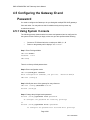
4.5.1 Using System Console
The following process shows how the host name and password can be configured via
the system console. Before you begin, make sure you have performed the following
y
Connect a VT100 terminal to the console port: 9600, 8, 1, N
y
Power on the gateway until it displays ”SMC-VIP08>”
Step 1: Enter Privileged Mode
SMC VoIP>enable
Password: ******
SMC VoIP#
There is no factory default password set.
Step 2: Enter configuration mode
SMC VoIP#configure terminal
Enter configuration commands, one per line.
End with CTRL/Z
SMC VoIP (config)#
Step 3: Modify the name of the gateway for easy reference
SMC VoIP (config)#hostname build-A
Build-A (config)#
Step 4: Change the privileged mode password.
Build-A (config)#password read <password>
To configure the password for read-only privilege
or
Build-A (config)#password write <password>
To configure the password for read and write privilege
Page 18/81
PN: 61100000050B
SMC-VIP04/08 PBX VoIP Gateway User's Manual
The privileges are divided into read-only and read write with different password.
After you have issued this command, you will then be asked to enter this password
each time you enter privileged mode. Any combination of characters and digits are
allowed with a maximum of 6 characters/digits. Here is an example:
Build-A (config)#password read psw
Build-A (config)#
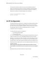
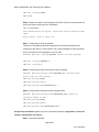
4.6 IP Configuration
The TigerAccess VoIP also requires you to configure the IP address, subnet mask and
default gateway so that the PBX VoIP gateway is able to connect to the IP network.
Since the device provides a 10BASE-T/100BASE-TX Ethernet interface with a default
auto-negotiation setting, it will work like a plug-and-play device, so a manual
configuration should not be necessary.
The system provides two types of IP assignment:
1. User manually assigned (static)
2. Through a DHCP server.
You can use the IP state command to select the appropriate mode that is used by your
network. The default value is set to User Manually assigned. On first receiving the
gateway, you must assign the IP address manually. If you want the gateway to receive
the IP address from the DHCP server, you must set the IP state mode to DHCP mode.
If a DHCP server is used, it will request the IP address from the server. However, if the
DHCP server does not respond within 1 minute, the system will attempt to use the user
assigned IP address.
Please note that when the system is in DHCP mode, the IP address received
from the DHCP server will be saved in the configuration file as the user assigned
IP.
Modifications will not take effect until after you restart your system.
Page 19/81
PN: 61100000050B
SMC-VIP04/08 PBX VoIP Gateway User's Manual
4.6.1 User Assigned IP Address
Using System Console Interface or Telnet
Step 1: Enter privileged mode
SMC VoIP>enable
Password: ******
SMC VoIP#
Step 2: Enter Configuration Mode
SMC VoIP#configure
Enter configuration commands, one per line.
End with CTRL/Z
SMC VoIP (config)#
Step 3: Assign the IP address and the subnet mask
Command: SMC VoIP (config)#ip address <ip-address> <subnet-mask>
SMC VoIP (config)#ip address 203.79.238.144 255.255.255.128
System need to restart
SMC VoIP (config)#
Step 4: Assign the default gateway
Command: SMC VoIP (config)#ip default-gateway <address>
PF1008 (config)#ip default-gateway 203.79.238.186
PF1008 (config)#
Step 5: Save the configuration to non-volatile memory immediately. If you do not save,
your new configurations will be lost when you power off. However, the system will save
the configuration automatically if (within 1 Minute) no input has been detected.
PF1008 (config)#dbflush
PF1008 (config)#
Step 6: go back to Privilege mode
PF1008 (config)#exit
Page 20/81
PN: 61100000050B
SMC-VIP04/08 PBX VoIP Gateway User's Manual
SMC VoIP#
Step 7: Restart the system so that your changes will take effect. After the restart
command is issued, the system will prompt for a confirmation.
SMC VoIP#restart
This command resets the system. System will restart operation code
agent.
Reset system, [Y]es or [N]o? Yes
Using Phone Set Interface
Step 1: Hook Off the handset
Step 2: Dial the PROG Access Code after hearing the dial tone (default is ##)
Step 3: Enter the Password (default is 0000)
Step 4: Enter code "02".
Step 5: Enter the IP address as "203","*","79","*","238","144" and "#" as
ending prompt. And you will hear the confirmation tone.
Step 6: Enter code "03" to begin the subnet mask configuration..
Step 7: Enter the subnetmask as "255", "*", "255", "*", "255", "*", "128"
and "#" as ending prompt. And you will hear the confirmation tone.
Step 8: Enter code "04" to begin the IP address for default gateway configuration.
Step 9: Enter the IP address of default gateway as "203", "*", "79", "*", "238",
"*", "186" and "#" as ending prompt. And you will hear the confirmation tone.
System must restart
Step 10: Enter code "98" then press "1" and "#" as ending prompt. Then you
will hear the confirmation tone, then the system will restart automatically.
Put on handset to hook on the phone for stop configuration.
4.6.2 Get the IP Add ress From a DHCP Server
Using System Console Interface
Step 1: Enter privileged mode
SMC VoIP>enable
Page 21/81
PN: 61100000050B
SMC-VIP04/08 PBX VoIP Gateway User's Manual
Password: ******
SMC VoIP#
Step 2: Enter Configuration Mode
SMC VoIP#configure
Enter configuration commands, one per line.
End with CTRL/Z
SMC VoIP (config)#
Step 3: Enable DHCP mode
SMC VoIP (config)#ip state dhcp
SMC VoIP (config)#
Step 4: Back to Privileged mode
SMC VoIP (config)#exit
SMC VoIP#
Step 5: Restart the system to enable DHCP mode. After the restart command is issued,
the system will prompt for a confirmation.
SMC VoIP#restart
This command resets the system. System will restart operation code
agent.
Reset system, [Y]es or [N]o? Yes
Using Phone Set Interface (please refer to for more detail information in Appendix A - Phone Set
Interface Configuration Procedures)
Step 1: Hook Off the handset.
Step 2: Dial the PROG Access Code after hearing the dial tone.
Step 3: Enter the Password.1
Step 4: Enter code "01" to begin configuring the DHCP state.
Step 5: Enter "1" to enable DHCP client and "#" as ending prompt. And you will
hear the confirmation tone. (Or enter "0" to disable DHCP client and "#" as
ending prompt).
1
The dafault password for Phone Set Interface is "0000".
Page 22/81
PN: 61100000050B
SMC-VIP04/08 PBX VoIP Gateway User's Manual
System must restart
Step 6: Enter code "98" then press "1" and "#" as ending prompt. Then
you will hear the confirmation tone, then the system will restart automatically.
Put on handset to hook on the phone for stop configuration.
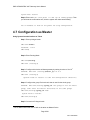
4.7 Configuration as Master
Using System Console Interface or Telnet
Step 1: Enter privileged mode
SMC VoIP>enable
Password: ******
SMC VoIP#
Step 2: Enter Routing Mode
SMC VoIP#routing
SMC VoIP (routing)#
Step 3: Configure this device as Master gateway by setting its value to 0.0.0.02
Command: SMC VoIP (routing)#master_ip 0.0.0.0
SMC VoIP (routing)#
(System needs to restart to take new configuration effective)
Step 4: Configure the group ID since that’s what is used for the whole group
Command: SMC VoIP(routing)#group_id <the group ID for the whole
group, same value for master and slaves in the same group>
SMC VoIP(routing)#group_id 2000
System need to restart
SMC VoIP(routing)#
Step 5: Go back to Privileged mode
2
For IP address other than 0.0.0.0 will not be taken as Master Device.
Page 23/81
PN: 61100000050B
SMC-VIP04/08 PBX VoIP Gateway User's Manual
SMC VoIP (routing)#exit
SMC VoIP#
Step 6: Restart the system for the settings to take effect. After the restart command is
issued, the system will prompt for a confirmation.
SMC VoIP#restart
This command resets the system. System will restart operation code
agent.
Reset system, [Y]es or [N]o? Yes
Step 7: Configuring the Prefix for gateway
This prefix of the gateway should be assigned by the network administrator and
configured to the device. It will be carried in the routing messages to notify the master
device of its prefix for other gateways to route its calls.
Command: SMC VoIP (routing)#prefix <prefix for this gateway>
SMC VoIP (routing)#prefix 99
SMC VoIP (routing)#
Step 8: Configuring the Internal Call Access code for gateway
Command: SMC VoIP(routing-code)#internal_ac <Internal Calls
Access code for this gateway>
SMC VoIP(routing)#code
SMC VoIP(routing-code)#
SMC VoIP(routing-code)#internal_ac *
Step 9: Configuring the Extension Number Length of PBX
Command: SMC VoIP(routing-code)#extension_len <length of
extension number of PBX>
SMC VoIP(routing)#code
SMC VoIP(routing-code)#
SMC VoIP(routing-code)#extension_len 3
Using Phone Set Interface (please refer to for more detail information in Appendix A - Phone Set
Interface Configuration Procedures)
Step 1: Hook Off the handset.
Page 24/81
PN: 61100000050B
SMC-VIP04/08 PBX VoIP Gateway User's Manual
Step 2: Dial the PROG Access Code after hearing the dial tone.
Step 3: Enter the Password.
Step 4: Enter code "06" to begin configuring for IP address of Master gateway.
Step 5: Enter the IP address for Master gateway as "0", "*", "0", "*", "0",
"*", "0" and "#" as ending prompt. And you will hear the confirmation tone.
Step 8: Enter code "05" to begin the group ID configuration.
Step 9: Enter the group ID as "2009" and "#" as ending prompt. And you will hear
the confirmation tone.
System must restart
Step 10: Enter code "98" then press "1" and "#" as ending prompt. Then
you will hear the confirmation tone, then the system will restart automatically.
Step 11: Enter code "09" to begin configuring for prefix for this gateway.
Step 12: Enter the prefix as "99" and "#" as ending prompt. And you will hear the
confirmation tone.
Step 13: Enter code "14" to begin configuring for Internal Call Access code for this
gateway.
Step 14: Enter the Internal Call Access Code as "*" and "#" as ending prompt. And
you will hear the confirmation tone.
Step 15: Enter code "28" to begin configuring for Extension Number Length of PBX
for this gateway.
Step 16: Enter the Extension Number Length of PBX as "3" and "#" as ending
prompt. And you will hear the confirmation tone.
Put on handset to hook on the phone for stop configuration.
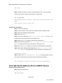
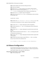
4.8 Slaves Configuration
Since the Master PBX gateway keeps a list of slaves, you need to join the group by
adding an entry into the Master for each Slave gateway. To add an entry you have to
input the MAC address to the member list of slave devices.
Using System Console Interface or Telnet on Master
Step 1: Enter privileged mode
Page 25/81
PN: 61100000050B
SMC-VIP04/08 PBX VoIP Gateway User's Manual
SMC VoIP>enable
Password: ******
SMC VoIP#
Step 2: Enter Routing Mode
SMC VoIP#routing
SMC VoIP (routing)#
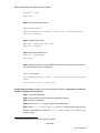
Step 3: Create an entry for this slave gateway
Command: SMC VoIP (routing)#slave add <ffffff-ffffff, the MAC
address of this Slave Device>
SMC VoIP (routing)#slave add 000362-000004
SMC VoIP (routing)#show slave
0001. 00-03-62-00-00-01
0002. 00-03-62-01-00-01
0003. 00-03-62-01-00-1B
0004. 00-03-62-01-00-30
0005. 00-03-62-00-00-04
0006. 00-03-62-01-00-06
Using Phone Set Interface to create entry for Slave gateway on Master gateway (please refer
to for more detail information in Appendix A - Phone Set Interface Configuration Procedures)
Step 1: Hook Off the handset.
Step 2: Dial the PROG Access Code after hearing the dial tone.
Step 3: Enter the Password.
Step 4: Enter code "22" to begin creating an entry for Slave gateway.
Step 5: Enter the last 6 characters of MAC address of the Slave gateway (00-03-6200-00-04) as "000004" and "#" as ending prompt. And you will hear the confirmation
tone.
Put on handset to hook on the phone for stop configuration.
Using System Console Interface or Telnet on slave
Step 1: Enter privileged mode
Page 26/81
PN: 61100000050B
SMC-VIP04/08 PBX VoIP Gateway User's Manual
SMC VoIP>enable
Password: ******
SMC VoIP#
Step 2: Enter Routing Mode
SMC VoIP#routing
SMC VoIP (routing)#
Step 3: Configure this device as Master gateway
Command: SMC VoIP (routing)#master_ip 211.21.40.180
SMC VoIP (routing)#
Step 4: Configure the group ID for that is used for the whole group
Command: SMC VoIP(routing)#group_id <the group ID for the whole
group, same value for master and slaves in the same group>
SMC VoIP(routing)#group_id 2000
System need to restart
SMC VoIP(routing)#
Step 5: go back to Privileged mode
SMC VoIP (routing)#exit
SMC VoIP#
Step 6: Restart the system for the settings to take effect. After the restart command is
issued, the system will prompt for a confirmation.
SMC VoIP#restart
This command resets the system. System will restart operation code
agent.
Reset system, [Y]es or [N]o? Yes
Step 7: Configuring the Prefix for gateway
This prefix of the gateway should be assigned by the network administrator and
configured to the device. It will be carried in the routing messages to notify the master
device of its prefix for other gateways to route its calls.
Page 27/81
PN: 61100000050B
SMC-VIP04/08 PBX VoIP Gateway User's Manual
Command: SMC VoIP (routing)#prefix <prefix for this gateway>
SMC VoIP (routing)#prefix 33
SMC VoIP (routing)#
Step 8: Configuring the Internal Call Access code for gateway (default is "*")
Command: SMC VoIP(routing-code)#internal_ac <Internal Calls
Access code for this gateway>
SMC VoIP(routing)#code
SMC VoIP(routing-code)#
SMC VoIP(routing-code)#internal_ac *
Step 9: Configuring the Extension Number Length of PBX
Command: SMC VoIP(routing-code)#extension_len <length of
extension number of PBX>
SMC VoIP(routing)#code
SMC VoIP(routing-code)#
SMC VoIP(routing-code)#extension_len 3
Using Phone Set Interface to Set the IP Address of Master gateway on Slave gateway
(please refer to for more detail information in Appendix A - Phone Set Interface Configuration
Procedures)
Step 1: Pick up the handset.
Step 2: Dial the PROG Access Code after hearing the dial tone.
Step 3: Enter the Password.
Step 4: Enter code "06" to begin to configure the IP address of Master gateway.
Step 5: Enter the IP address of the Master gateway as "211", "*", "21", "*",
"40", "*", "180" and "#" as ending prompt. You will hear the confirmation tone.
Step 8: Enter code "05" to begin the group ID configuration.
Step 9: Enter the group ID as "2009" and "#" as ending prompt. And you will hear
the confirmation tone.
System must be restarted
Step 10: Enter code "98" then press "1" and "#" as ending prompt. Then
you will hear the confirmation tone, after which the system will restart automatically.
Page 28/81
PN: 61100000050B
SMC-VIP04/08 PBX VoIP Gateway User's Manual
Step 11: Enter code "09" to begin configuring for prefix for this gateway.
Step 12: Enter the prefix as "33" and "#" as ending prompt. And you will hear the
confirmation tone.
Step 13: Enter code "14" to begin configuring for Internal Call Access code for this
gateway.
Step 14: Enter the Internal Call Access Code as "*" and "#" as ending prompt. And
you will hear the confirmation tone.
Step 15: Enter code "28" to begin configuring for Extension Number Length of PBX
for this gateway.
Step 16: Enter the Extension Number Length of PBX as "3" and "#" as ending
prompt. And you will hear the confirmation tone.
Put on handset to hook on the phone for stop configuration.
Page 29/81
PN: 61100000050B
SMC-VIP04/08 PBX VoIP Gateway User's Manual
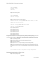
5 Basic Configuration
5.1 System Console Modes
end
Code
exit
code
Routing
exit/end
exit
Routing
login
enable
EXEC
configure
Privileged
disable
Configuration
exit/end
channel
line console
exit
end
Console
exit
Channel
end
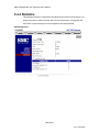
5.2 System Management
The following general information is needed to configure the system with appropriate
routing information to route calls between PBXs and voice gateways. You must
configure the prefix and group ID that will be used inside the group of the PBX VoIP
gateway. The Master gateway IP address is essential for a PBX VoIP gateway to
synchronize the routing information.
Page 30/81
PN: 61100000050B
SMC-VIP04/08 PBX VoIP Gateway User's Manual
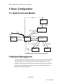
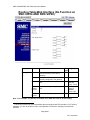
5.2.1 Information-We b Management
Page 31/81
PN: 61100000050B
SMC-VIP04/08 PBX VoIP Gateway User's Manual
Category
Entry
Information Host
Name
System
Restart
Description
Data
Type
Name of the gateway for RW
the system administrator
to distinguish this gateway
from others. It will also be
used as a prompt in the
system console.
RW
Location
This entry allows the
system administrator to
identify the gateway’s
location.
Software
Version
BootRom
Version
CPU
Board
Version
FXS
Board
Version
Host UpTime
Base
Ethernet
Address
Date
Time
Restart
Mode
Current software version RO
Range
Any string
length up to 48
characters can
be used. You
may input a total
of 255
characters.
However once a
length of 48 is
reached any
characters
above that will
be truncated.
Any string
length up to 48
characters can
be used. You
may input a total
of 255
characters.
However once a
length of 48 is
reached any
characters
above that will
be truncated.
X.XX
Current BootRom Code
version
Current CPU Board
version
RO
X.XX
RO
X.XX
Current FXS Board
version
RO
X.XX
System Up-Time after last RO
Warm Start
The Ethernet Address of RO
this device
X.XX
Current date
RW
Current Time
RW
RW
This pull-down menu
allows you to select the
restart mode:
None: No system restart
will be issued:
Cold Start: The system
will restart from the
beginning. The running
code will be
yyyy/mm/dd
hh:mm:ss
NONE
Cold Start
Warm Start
XX-XX-XX-XXXX-XX
Page 32/81
PN: 61100000050B
SMC-VIP04/08 PBX VoIP Gateway User's Manual
Category
Entry
Description
Data
Type
Range
decompressed from the
flash memory and initiate
all the system
parameters.
Warm Start: The system
will restart but the running
code will not be
decompressed.
5.2.2 Console Comm ands -System Information
Category
Entry
Information Host
Name
Location
Software
Version
BootRom
Version
CPU
Board
Version
FXS
Board
Version
Host UpTime
Base
Ethernet
Address
Date
Time
Date
Time
System
Restart
Restart
Mode
Console Mode Console Command
hostname <string>
Data
Type
RW
Configuration location <string>
EXEC/Privilege Show Version
RW
RO
EXEC/Privilege Show Version
RO
EXEC/Privilege Show Version
RO
EXEC/Privilege Show Version
RO
EXEC/Privilege Show Version
RO
EXEC/Privilege Show Version
RO
EXEC/Privilege
EXEC/Privilege
Configuration
Configuration
Privilege
RO
RO
RW
RW
WO
Configuration
Show date
Show time
date <yyyy/mm/dd>
time <hh:mm:ss>
restart for warm start
reload for cold start
5.2.3
Page 33/81
PN: 61100000050B
SMC-VIP04/08 PBX VoIP Gateway User's Manual
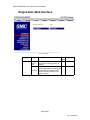
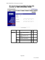
Registration-Web Interface
Category
Entry
Registration Current
Device
Role
As Master
/
As Slave
Description
Data Range
Type
RO
Slave if this Device is currently
configured as Salve gateway (or
Master)
RO
Name of the gateway for the
system administrator to distinguish
this gateway from others. It will
also be used as a prompt in the
system console.
Page 34/81
PN: 61100000050B
SMC-VIP04/08 PBX VoIP Gateway User's Manual
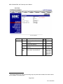
As a Master
Category
Entry
Description
Data Range
Type
Act As
Group ID The Group ID for PBX VoIP
RW 0~2147423
Master
Gateway
467
Prefix
The prefix is the code used to route RW 1~9999
a call to this gateway
Slave
Capacity The allowed capacity for slave
RO 31 not
Registration
entries
including
the Master
Quantity Current registered slaves
RO 0~31
Slave List The list of MAC address of current RO
registered slaves
Add
Entry to add MAC address of slave RW XX-XX-XXSlaves
XX-XX-XX
Delete
Entry to delete MAC address of
RW XX-XX-XXSalves
slave
XX-XX-XX
Page 35/81
PN: 61100000050B
SMC-VIP04/08 PBX VoIP Gateway User's Manual
As a Slave
Category
Entry
Description
Data Range
Type
Act As Slave Group ID The Group ID for PBX VoIP
RW 0~2147423
Gateway
467
Prefix
The prefix is the code used to route RW 1~9999
a call to this gateway
Master IP The IP Address of the Master
RW XXX.XXX.X
Address gateway
XX.XXX
Group Id The Hold Time for Group Id in the RW Forever|0.5
device when it is powered off
hr|1.0 hr|1.5
Hold
hr|2.0 hr|2.5
Time3
hr|3.0 hr|3.5
hr|4.0 hr|4.5
hr|5.0 hr
3
The Group Id Hold tine is used for protect the group Id to prevent the intruders from stole a device
and re-installed it in another place.
Page 36/81
PN: 61100000050B
SMC-VIP04/08 PBX VoIP Gateway User's Manual
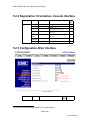
5.2.4 Registration In formation- Console Interface
Category
Entry
Console Mode Console Command
Registration Group Id Routing
Prefix
Routing
Master IP Routing
Add Slave Routing
Delete
Routing
Salve
Group Id Routing
Hold Time
Slave List Routing
group_id <number>
prefix <number>
master_ip
<xxx.xxx.xxx.xxx>
Slave add <ffffffffffff>
Slave del <ffffffffffff>
gid_tmr <0-255>
show slave
4
Data
Type
RW
RW
RW
RW
RW
RW
RO
5.2.5 Configuration-W eb Interface
Category
4
Entry
Description
Data Range
Type
show slave only work on Master gateway in Console Interface.
Page 37/81
PN: 61100000050B
SMC-VIP04/08 PBX VoIP Gateway User's Manual
Configuration Transit
Call
Function
CDR
Report
Greeting
Mode
Allow or Disallow Transit Call
RW
Allow or Disallow CDR report
RW
output5
Default for not using the recorded RW
Greeting Message or Recording
for using the recorded Greeting
Message6
Auto
Whether or not your PBX equipped RW
Attendant with Auto Attendant function
Slave
The UDP port number to carry Call RW
UDP Port Control signaling from this Slave
No.
devices with other gateways
The UDP port number to carry Port RW
Master
UDP Port Information signaling to Master
device
No.
RTP Base The Base RTP port number to
Port No. carry voice streaming between
gateways
RW
Enable/Dis
able
Enable/Dis
able
Default/Rec
ording
Provided/N
ot Provided
1025~6553
5 (default
value is
2000)
1025~6553
5 (default
value is
2000)
2049~6553
5
Note 2 The Master UDP port number on Salve devices should be the same as the definition on
Master device. But The Slave UDP port number for each slave can be different for each
device.
The configurations of UDP port number and RTP port number are related to the firewall setting
of your network. Please consult with your network administrator before changing it.
5
CDR report work only on the model that with extra RS-232 CDR output interface
You can use the Phone Set Interface to configure the Skip Greeting Access Code (item code 30)
to specify the access code while trying to skip the greeting message even if this function is Enabled.
6
Page 38/81
PN: 61100000050B
SMC-VIP04/08 PBX VoIP Gateway User's Manual
5.2.6 Configuration Information- Console Interface
Category
Entry
Console Mode Console Command
Routing
Transit
Call
Function
CDR
Report
Greeting
Mode
Auto
Attendant
Master
UDP Port
No.
Slave
UDP Port
No.
RTP Base
Port No.
Routing
transit_call
<enable/disable>
Routing
cdr <enable/disable>
RW
Routing
greet_mode
<default/recoding>
auto_attn
<enable/disable>
udp_port master <065535>
RW
Routing
Routing
Data
Type
RW
RW
RW
Routing
udp_port slave <065535>
RW
Routing
rtp_base <0-255>
RW
5.2.7
Page 39/81
PN: 61100000050B
SMC-VIP04/08 PBX VoIP Gateway User's Manual
Numbering Plan-Web Interface
Category
Entry
Numbering
Plan
Country
Code
Description
Data Range
Type
RW 1~999
The Country Code where this
gateway is for receiving incoming
calls from foreign countries
RW
Area
The Area Code where this
Code
gateway is for receiving incoming
calls from other areas
Extension The number of digits for PBX lines RW
Digits
Access Code Internal
Define the Access Code to make a RW
call in-between the PBX gateways
in the same group (See application
in 3.1 Internal Calls)
Local
Define the Access Code to force a RW
PSTN
call out from FXO interface on the
PBX gateway to PSTN7
Transit
Define the Access Code to make a RW
call from PSTN into the FXO port
on this device and call out from
FXO interface on the remote PBX
gateway to PSTN (This function
take effective only when you got
FXO interfaces exist in your group)
1~999
1-9
[1~9,*,#][0~
9], example
"*12345"
[1~9,*,#][0~
9], example
"*12345"
[1~9,*,#][0~
9], example
"*12345"
8
7
8
This function works only on those models that with FXO interface.
This function works only on those models that with FXO interface.
Page 40/81
PN: 61100000050B
SMC-VIP04/08 PBX VoIP Gateway User's Manual
5.2.8 Numbering Pla n Information- Console
Interface
Category
Entry
Console Mode Console Command
Numbering
Plan
Country
Code
Area
Code
Extension
Digits
Internal
Code
country <1-999>
Code
area <1-999>
RW
Code
extension_len <1-9>
RW
Code
internal_ac <Access
Code>
local_pstn_ac <Access
Code>
transit_ac <Access
Code>
RW
Access
Code
Local
PSTN
Transit
Code
Code
Data
Type
RW
RW
RW
Note 3 Access Code can be a character range from [*|#|0~9] or the character plus a number
in 1 to 5 digits. For examples, you can set your access code as "*", "*1", "*999" and
etc.
5.2.9
Page 41/81
PN: 61100000050B
SMC-VIP04/08 PBX VoIP Gateway User's Manual
International Code-Web Interface
Category
International
Access Code
(Outbound)
International
Access Code
(Inbound)9
Entry
Data
Type
Dial Code The code that the gateway need to RW
add while wants to make out an
international call through this
gateway
RO
Capacity The number of In-bound
International Access Code entries
that are allowed to specified in this
gateway
Quantity The number of In-bound
RO
International Access Code entries
that are currently specified in this
gateway
RO
Code List The list of Inbound International
Access Code that are currently
configured in this gateway
Add
The Access Code that you are
WO
Entries
going to Add into the Code List
Delete
Entries
Description
The Access Code that you are
going to Remove from the Code
List
WO
Range
1-999
5
0-5
[0~9],
example
"012", "002"
[0~9],
example
"012", "002"
[0~9],
example
"012", "002"
Note 4 The Inbound International Access Code is used to analyze the number that gateway
is receiving from a local PSTN via FXO interface or from a PBX via FXS interface. The
receiving numbers that carry the specified Inbound International Access Code, will be
Page 42/81
PN: 61100000050B
SMC-VIP04/08 PBX VoIP Gateway User's Manual
routed to the remote gateway that has the defined routing entry to access this
International Access Code and be routed to its. Otherwise, this call will be treated as
an international call from local PSTN and will not enjoy the Toll-bypass advantage. If
your gateway is not allowed to make an international call through the remote gateway,
leave the In-bound International Access Code entry empty.
5.2.10 International C ode Information- Console
Interface
Category
Entry
Console Mode Console Command
Data
Type
RW
International
Access
Code
(Outbound)
International
Access
Code
(Inbound)
Dial Code Code
dial_code
international <1-999>
Code List Code
Add
Code
Entries
Delete
Code
Entries
show ac_summary
intn_code add <1-999>
RO
RW
intn_code del <1-999>
RW
Note 5 The Access Code here is the same as the code that you are dialing locally to make
an international call.
5.2.11
Page 43/81
PN: 61100000050B
SMC-VIP04/08 PBX VoIP Gateway User's Manual
Long Distance Code-Web Interface
Category
Entry
Long
Dial Code
Distance
Access Code
(Outbound)
Long
Capacity
Distance
Access Code
(Inbound)9
Quantity
Description
Applies to the device that have
FXO interface.
Data Range
Type
NA NA
NA
The number of In-bound Long
Distance Call Access Code entries
that are allowed to specified in this
gateway
The number of In-bound Long
NA
Distance Call Access Code entries
that are currently specified in this
gateway
Code List The list of Inbound Long Distance NA
Call Code that are currently
configured in this gateway
Add
The Access Code that you are
NA
Entries
going to Add into the Code List
Delete
The Access Code that you are
NA
Entries
going to Remove from the Code
List
NA
NA
NA
NA
NA
5.2.12 Long Distance Code Information- Console
Interface
Category
Entry
Console Mode Console Command
Long
Distance
Access
Code
(Outbound)
Long
Distance
Access
Code
(Inbound)
Dial Code Code
Code List Code
Add
Code
Entries
Delete
Code
Entries
dial_code
long_distance
Data
Type
RW
<1-999>
show ac_summary
long_distance add <1999>
long_distance del <1999>
RO
RW
RW
Note 6 The Access Code here the same as the code that your are dialing locally to make a
Long Distance call.
9
If users wish to use the FXO interfaces on other VoIP gateways within the same group. You should
specify the In-bound Access code, otherwise your call can not be redirect to remote gateway that
with FXO interfaces.
Page 44/81
PN: 61100000050B
SMC-VIP04/08 PBX VoIP Gateway User's Manual
5.2.13
Page 45/81
PN: 61100000050B
SMC-VIP04/08 PBX VoIP Gateway User's Manual
Routing Table-Web Interface (No Function on
SMC-VIP04 AND SMC-VIP08)
Category
Entry
Description
Routing Table Capacity
Data Range
Type
RO 20
The numbers of allowed entries for
route a call to the PSTN via this
gateway10
Quantity The number of routing entries that are RO
currently configured in the gateway
Route List The list of route entries with its route RO
cost
Add
/Modify
Entries
To Add or Modify a routing entry or its WO
cost
Delete
Entries
To delete a routing entry
WO
0-20
Format:
[Routing
Entry - Cost]
Routing
Entry: 0999999;
Cost: 1~99
0-999999
Note 7 For example, if a gateway is installed in the USA and wants to be the routing
10
This function works only on those gateways that are equipped with FXO interfaces. For FXS only
gateways, you are not be able to see it in the Member List under the Topology icon with Web
Interface.
Page 46/81
PN: 61100000050B
SMC-VIP04/08 PBX VoIP Gateway User's Manual
gateway for all calls in the group to Ottawa - Canada. The routing entry for this
example will be 1613 with cost 1 in this gateway you also need to specify the outbound
International Access Code 011. So a call from gateway in Hong Kung will be route to
PSTN in USA with dial out number 011-1-613-xxxx-xxx to Ottawa-Canada.
5.2.14 Routing Table- C onsole Interface
Category
Entry
Console Mode Console Command
Routing
Table
Route List Routing
Add
Routing
/Modify
Entries
Delete
Routing
Entries
show call_route
call_route add <0999999> <1-99>
call_route del <0999999>
Data
Type
RO
WO
WO
Note 8 To modify a routing entry in Console Interface, you need to delete that entry and add
it with the new value that you wants to modify.
5.2.15
Page 47/81
PN: 61100000050B
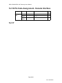
SMC-VIP04/08 PBX VoIP Gateway User's Manual
Pin Code Assignment-Web Interface(No
function on SMC-VIP08/SMC-VIP04)
Category
Entry
Description
Data Range
Type
PIN Code For Capacity The allowed entries for PIN codes RO 32
Transit Call
to make a transit call via this
gateway
Quantity The number of PIN codes that are RO 0-32
currently configured in this
gateway
Code List The list of PIN codes that is
RO
configured in this gateway
Add
To Add a PIN Code entry
WO 0-99999999
Entries
Delete
To delete a PIN Code entry
WO 0-99999999
Entries
Page 48/81
PN: 61100000050B
SMC-VIP04/08 PBX VoIP Gateway User's Manual
5.2.16 Pin Code Assig nment- Console Interface
Category
Entry
Console Mode Console Command
Routing
Table
Code List Routing
Add
Routing
Entries
Delete
Routing
Entries
show pin
pin add <0-99999999>
<1-99>
pin del <0-99999999>
Data
Type
RO
WO
WO
5.2.17
Page 49/81
PN: 61100000050B
SMC-VIP04/08 PBX VoIP Gateway User's Manual
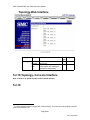
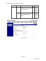
Topology-Web Interface
Category
Entry
Description
Topology
Total
Member
Member
List
The number of Member in the
same group
The list of gateways in the same
group. Display the prefix that is
specified for that gateway11
Data Range
Type
RO
RO
5.2.18 Topology- Con sole Interface
Note 9 There is no similar function in the Console Interface
5.2.19
11
For those models that are equipped with FXO interfaces. The route list will be displayed with the
Prefix in the Member List.
Page 50/81
PN: 61100000050B
SMC-VIP04/08 PBX VoIP Gateway User's Manual
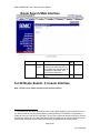
Route Search-Web Interface
Category
Entry
Route Search IP
Address
Route
Entry
Description
Data Range
Type
RO
If the Prefix that specified in the
previous section has been found,
the IP address of that gateway will
be displayed. Otherwise, "Not
Found" will be displayed.
WO
The Route Entry that intend to
search12
5.2.20 Route Search- C onsole Interface
Note 10 There is no similar function in the Console Interface
12
This function has the same restriction as other routing table related function. In another word, if
you wants to find an entry that is specified in a gateway without FXO interface. The gateway in
unable to route your calls to PSTN through it. So you can not have the search result even you had
specified the routing entry in it. More than that, for the searching entry do not allow wild card, so you
need to inter the search criteria exactly the same as you specified in the routing entries.
Page 51/81
PN: 61100000050B
SMC-VIP04/08 PBX VoIP Gateway User's Manual
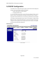
5.3 TCP/IP Configuration
The TCP/IP can be configured through the system console and the Web management
interface. There are two ways to obtain the IP address:
1. System administrator manually assigned.
2. Through the DHCP server.
You can select which way you prefer to get the IP through setting the IP State mode. If
Manual is selected, the administrator must assign it manually. If DHCP is selected, it
will get the IP from the DHCP server. You need to set up a DHCP server and configure
its IP address so that the gateway is able to locate it. If the gateway is configured using
DHCP mode and it cannot find the DHCP server, it will use the IP that was previously
configured. After the gateway has successfully acquired the IP address, it will update
the newly received (manually configured) IP.
Web Management
Page 52/81
PN: 61100000050B
SMC-VIP04/08 PBX VoIP Gateway User's Manual
Category
Entry
Information IP State
Now
Next
Description
Data Range
Type
Defines the mode used to acquire RW Manual
Auto (DHCP)
an IP address:
Manual: static address mode. The
system administrator must assign
the IP address directly from the
system console or web page.
Auto (DHCP): If this mode is
selected, the IP will be
automatically selected from the
DHCP server.
Displays the current IP address, RO subnet mask and default gateway.
Sets the IP address, subnet mask RW IP address
and default gateway that will be
used (after Restart) if the IP state
is set to Manual mode.
Console Commands
Category
Entry
Console Mode Console Command
Information IP State configuration ip state <user | dhcp>
IP
configuration ip address <ip address>
<subnet mask>
Address
Default
configuration ip default-gateway <ip
address>
Gateway
Page 53/81
PN: 61100000050B
SMC-VIP04/08 PBX VoIP Gateway User's Manual
5.4 Channel Management
5.4.1 Summary
Category
Summary
Entry
Description
Data Range
Type
Channel
The channel number. It displays RO Two groups
Group/Port format. Port 2 in
and 4 ports
group 1 will be shown as 1/2
for each
group
I/F Type
Shows the ports interface type. RO FXS
This model shows FXS.
Operating Shows the operation status of
RO Enable
Status
this port. Enable/Disable
Disable
Input Gain Shows the currently configured RO -6 db to 6 db
input gain
Output
It shows the currently configured RO -6 db to 6 db
Gain
output gain
Page 54/81
PN: 61100000050B
SMC-VIP04/08 PBX VoIP Gateway User's Manual
5.4.2 Regional
The configuration shown in this page applies to each channel of the entire device.
Category
Entry
Information Hook
Flash
Time
DTMF Play
out
Duration
Description
Data Range
Type
Defines the time frame of a break RW 200ms
to be treated as a Flash signal.
300ms
400ms
500 ms
600 ms
700 ms
800 ms
900 ms
1000 ms
Defines how long the DTMF will be RW 100
150
sent when the gateway receives a
200
DTMF Play Out message from the
250
Call Agent.
300
350
400
450
500
550
600
650
700
750
800
Page 55/81
PN: 61100000050B
SMC-VIP04/08 PBX VoIP Gateway User's Manual
Inter Digit Defines the inter digit time of the RW
Time
DTMF when the gateway receives
a DTMF Play Out message.
Busy Tone
Spec
Frequenc f1, f2
y
Cadence on, off The on and off duration to
play the tone
100
150
200
250
300
350
400
(300 ~
3000Hz)
(100 ~
5000ms)
Console Commands
Category
Entry
Console
Console Command
Mode
Flash <200 – 1000>
Channel
Not supported in the console
Information
DTMF Play
out
Busy Tone
Spec.
Flash Time
Duration
Inter Digit Time
There is no such function in Command Line
Frequency
Interface
Cadence
5.4.3
Page 56/81
PN: 61100000050B
SMC-VIP04/08 PBX VoIP Gateway User's Manual
Channel Configuration
The configuration shown on this web page applies to a single individual channel. You
must select a channel and configure it to your particular specifications.
Web Management
Page 57/81
PN: 61100000050B
SMC-VIP04/08 PBX VoIP Gateway User's Manual
Category
Entry
Description
Data Range
Type
Channel
Channel number. Displays in RW One or two
Group/Port format. Port 2 in
groups and
group 1 will be shown as 1/2
4 ports for
each group.
Default: 1/1
Information I/F Type
Displays the channel interface RO
type. The SMC-VIP08 supports
FXS only.
Admin State Enables/disables the channel. RW Enable,
Disable
Operational Displays the current operational RO
State
states.
Voice
Codec Type When assigning the preferred RW G.711 A Law,
G. 711 u Law,
port codec type.
G.729AB
Packet Time Defines how long the gateway RW
will send a voice packet to the
destination port.
Please refer to the Available
Packet time selection table.
Input Gain
Input gain selection.
Output Gain
Output gain selection.
RW
10ms –
G.711,
20ms –
G.711,
G.729A,
30ms G.711,
40ms G.729A,
60ms G.729A,
80ms G.729A
-6, -5, -4, -3,
-2, -1, 0, 1,
2, 3, 4, 5, 6
db
-6, -5, -4, -3,
-2, -1, 0, 1,
2, 3, 4, 5, 6
db
Table: Available packet time supported by different coding type
Codec Types
G.711
G.729A
10ms
√
20ms
√
√
30ms
√
40ms
√
60ms
√
80ms
√
Page 58/81
PN: 61100000050B
SMC-VIP04/08 PBX VoIP Gateway User's Manual
Console Commands
Category
Entry
Information Admin
State
Voice
Codec
Type
Packet
Time
Input
gain
Output
Gain
Console Mode Console Command
channel <group/port> <enable
Console
| disable>
Not supported
-
Not supported
Console
gain input <group/port> <-6 |
-5 | -4 | -3 | -2 | -1 | 0 |
1 | 2 | 3 | 4 | 5 | 6>
gain output <group/port> <-6
| -5 | -4 | -3 | -2 | -1 | 0
| 1 | 2 | 3 | 4 | 5 | 6>
Console
Page 59/81
PN: 61100000050B
SMC-VIP04/08 PBX VoIP Gateway User's Manual
5.4.4 Statistics
This web page shows the configuration and statistical information of each channel. You
simply must select a channel number and click the refresh button. The gateway will
then return a page showing its current configuration and statistical data.
Web Management
Page 60/81
PN: 61100000050B
SMC-VIP04/08 PBX VoIP Gateway User's Manual
Category
Entry
Description
Data Range
Type
Channel
The channel number. Shown RW Two groups
in the Group/Port format. Port
and 4 ports
2 in group 1 will be shown in
for each
1/2
group.
1/1
Current Codec Displays the current codec
RO
Type
that the channel is using
Packet Time
Displays the current packet RO
(msec)
time this channel is using
VAD
Displays VAD administrative RO
status
Echo
Displays Echo Cancellation RO
Cancellation
administrative status
RO
Jitter Buffer
Displays how long the jitter
(msec)
buffer is used in this channel.
If the channel has no traffic,
the last value that was used
by the previous call will be
displayed. 0 stands for AUTO
jitter buffer.
DTMF Filter
Displays DTMF Filter
administrative status
RO
Busy Time
Displays the length of time
(sec)
this channel has been in a
busy state. (Includes
incoming and outgoing calls.)
The busy time will be reset
when you power off.
Reset Busy
A check box. If checked and RW
Time
the refresh button is clicked,
Busy Time will be reset.
Call Attempt
Displays the number of call RO
attempts that have been
made.
Successful
Displays the number of
RO
Outgoing Call successful outgoing calls that
have been made.
Incoming Call Displays the total number of RO
incoming calls
Successful
Displays the number of
RO
Incoming Call successful incoming calls
Page 61/81
PN: 61100000050B
SMC-VIP04/08 PBX VoIP Gateway User's Manual
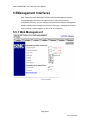
5.5 Management Interfaces
SMC TigerAccess VoIP Gateways are flexible with Web Management Interface,
Console Management Interface through RS-232 or Telnet and Phone Set
Configuration Interface. You can configure the parameters for different management
interfaces through web management interface or through the management interface
itself. Following is a demonstration on how it can be configured:
5.5.1 Web Managem ent
Page 62/81
PN: 61100000050B
SMC-VIP04/08 PBX VoIP Gateway User's Manual
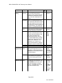
Category
Entry
Console
Setting
Session
Timeout
Description
Data Range
Type
RW 0 – 255
minutes
A session (system console or
Telnet) will be automatically
logged-out if the activity timer has
exceeded the maximum timeout
value. The value 0 stands for no
timeout.
RW
Password The session will be halted if the
Threshold number of invalid password tries
has reached the threshold. Please
note that it applies to the console
and Telnet only, it does not apply to
the web interface. The value of 0
stands for no password threshold.
Silent
Determines how long the console RW
Time
will halt when the invalid password
tries has reached the threshold.
RW
Baud Rate System console baud rate
selection. If the baud rate is set to
any rate other then 9600 you will
see a string of garble in the
terminal during system boot up.
The console goes back to normal
after boot up. This is because the
system is set at 9600, 8, 1, N
during boot up. Therefore it is
highly recommended to configure
the system console to 9600 baud.
Data Bits Data bits selection
RW
Stop Bits Stop bits selection
RW
Phone Set
Access
The Access Code to start Phone RW
Programming Code
Set Programming Mode (see 6
Appendix A - Phone Set Interface
Configuration Procedures for more
detail information)
Password The password required to enter
RW
into the Phone Set Programming
Mode after entering the Access
Code
Web
User
The Authentication ID to begin the RW
Authentication Name
Web Management Interface. The
Read & Write account can read
and write information via Web
browser. The Read only account
can read information only.
0 – 255
0 – 255
minutes
2400,
9600,
19200,
38400
7, 8 bits
1, 2 bits
## as
default,
1-6 digits,
the first digit
can be "#"
or "*"
0000 as
default,
1-4 digits
WEB as
default for
Read and
Write,
BLANK for
read only
1-12
characters
in string
format
Page 63/81
PN: 61100000050B
SMC-VIP04/08 PBX VoIP Gateway User's Manual
Category
Entry
Description
Data Range
Type
Password The Password for the
WO Empty
Authentication ID to begin the Web
password
Management Interface
as default,
Allow string
up to 6
characters
Confirm Re-enter the Password for the
WO Empty
Password Authentication ID to confirm enter
password
into the Web Management
as default,
Interface
Allow string
up to 6
characters
Page 64/81
PN: 61100000050B
SMC-VIP04/08 PBX VoIP Gateway User's Manual
5.5.2 Console Comm ands
Category
Line
Console
Password
Entry
Console Mode Console Command
time-out <0-255> in minutes
Session Console
Timeout
databits <7/8>
Databits Console
password-thresh <0-255>
Password Console
Threshold
silent-time <0-255> in
Silent
Console
minutes
Time
speed <2400 | 9600 | 19200 |
Baud Rate Console
38400 >
time-out <0-255> in minutes
Time Out Console
Console Configuration password console level <1-15>
<password> in 6 characters
Level
for "enable"
Phone
Configuration password phone digits in 4
digits (0~9, default is 0000)
Configuration password web username
Web
<username> in 6 characters
Configuration password web password
<password> in 6 characters
Page 65/81
PN: 61100000050B
SMC-VIP04/08 PBX VoIP Gateway User's Manual
5.6 Software Upgrade
The software upgrade can only be done through a TFTP server, so you must have a
TFTP server running on the network and the new firmware must be saved on the
server. You can issue a command to download it from the web management page or
system console. The following steps are a guide to downloading the new firmware from
the TFTP server through a web interface.
Step 1. Make sure the TFTP server is running and the newly received firmware is
saved on the server.
Step 2. Fill in the IP address of the TFTP server and the path/filename information.
Step 3. Check the Begin Download box
Step 4. Click the Apply button to start downloading the firmware. The gateway will
display a page with the download status showing: in-progress
Step 5. You can check the download status by manually clicking the Apply button
repeatedly and holding until the return page shows a successful download. If
the gateway cannot find the TFTP server or the filename, the download status
in the returned page will show Time-out or Error.
Step 6. After the code has been successfully downloaded, you have to initiate a coldstart. The new code will not take effect until you issue a cold-start command.
You can issue a cold-start command through the system console or through
the web management page in the System Management.
Page 66/81
PN: 61100000050B
SMC-VIP04/08 PBX VoIP Gateway User's Manual
Category
Entry
Description
Data Range
Type
Firmware
Version
Displays the firmware version RO
TFTP Server IP Address
Specifies the IP address of the RW IP address
TFTP server. A domain name is
and domain
also allowed.
name
RW
Specifies the path of the
Download
filename in the TFTP server
Path/File
such as:
Name
C:/runtime.tcw
Start
A check out box to enable the RW
Downloading system to begin downloading.
When checked and apply is
clicked, the system will
commence downloading.
Page 67/81
PN: 61100000050B
SMC-VIP04/08 PBX VoIP Gateway User's Manual
5.6.1 Console Comm ands
Using the system console to upgrade the firmware is quite similar to using the Web
management interface. You must run the TFTP server first. You must also assign the IP
address of the TFTP server and filename separately. After they are configured, issue a
copy command to initiate the firmware upgrade. You can also combine three
commands in one. Following these steps:
Step 1: Configure TFTP server and filename
a) Separate command:
1. tftp server <ip-address | domain name>
2. tftp filename <filename>
3. copy tftp:///
b)Combined command
copy tftp://<ip-address>/<filename>
ITG3#copy tftp://192.168.0.201/a:\runtime.tcw
TFTP Server: 192.168.0.201
a:\runtime.tcw
Downloading....
Step 2: Gateway is downloading the firmware. Wait for the result.
ITG3#copy tftp://192.168.0.201/a:\runtime.tcw
TFTP Server: 192.168.0.201
a:\runtime.tcw
Downloading....
Download success
System must reload
Step 3: If the gateway download successfully, make a cold-start to launch the new
code.
ITG3#reload
Page 68/81
PN: 61100000050B
SMC-VIP04/08 PBX VoIP Gateway User's Manual
Category
Entry
Console Mode Console Command
TFTP Server IP
Configuration tftp server <ip-address |
domain name>
Address
Download Configuration tftp filename <filename>
Path/File
Name
Privileged
Two commands: If the TFTP server IP
Start
address and filename have been
Downloadi
assigned:
ng
copy tftp :///
Or specify the address and file name
at the same time:
copy tftp ://<ip-address>/
<filename>
If the TFTP server IP address and
filename have been assigned:
If the TFTP servers IP has not been
assigned You may specify the
address and file name
simultaneously:
Page 69/81
PN: 61100000050B
SMC-VIP04/08 PBX VoIP Gateway User's Manual
5.7 Additional Console Commands
Comands
area
auto_attn
call_route
code
country
dbflush
delete nvram
Purpose
Set the device area code
Set auto attendant status
Set or delete an entry of routing table
Enter access code configuration mode
Set the device country code
Immediately saves the current configuration onto non-volatile
memory. It is recommended that you issue this command
after entering configuration changes. The system will
automatically execute this command if it has detected no
input within a certain time frame.
Resets the configuration to the default value. Also known as
a Factory Reset.
delete nvram
Set the access number for out-bound analysis
To exit current mode and go back to upper level
Go back to Privilege mode
Set the number of digits for PBX extension
Timer to erase group id when system power down
Set the group id
Set master's IP address
Set the internal access code for entra-gateway calls
Set the international access code for in-bound analysis
Set the local PSTN trunk access code, if exists
Set the long distance access code for in-bound analysis
Set or delete a pin code
Set the device prefix number
Set the device phone set program mode access code
Set the region_id information for proper ringing pattern,
cadence and other regional related profile.
rtp_base
Set the RTP base port number
service_port
Set the Service port for Telnet or Web
show ac_summary
Show summary of access code configuration
show call_route
Show the device routing table
show channel
Shows the channel summary
show date
Shows date
show ethernet
Shows Ethernet information
show flash
Shows flash time settings
show history
Shows the commands that was issued
show ip
Shows IP settings
show line
Shows console settings
show location
Shows location information
show pin
Show all pin codes the device all of call password
show routing-config Show the device current operating routing mode
configuration
show running-config Shows current running configuration
show slave
Show slave device if the device is master
show tftp
Shows TFTP server IP address
show time
Shows current time
show version
Shows firmware version
dial_code
exit
end
extension_len
gid_tmr
group_id
master_ip
internal_ac
intn_code
local_pstn_ac
long_distance
pin
prefix
prog_ac
region_id
Page 70/81
PN: 61100000050B
SMC-VIP04/08 PBX VoIP Gateway User's Manual
slave
transit_ac
transit_call
udp_port
Set or delete a slave device
Set the transit access code
Enable or disable the device transit call
Set UDP port number
Page 71/81
PN: 61100000050B
SMC-VIP04/08 PBX VoIP Gateway User's Manual
6 Appendix A - Phone Set Interface
Configuration Procedures
6.1 Configuration procedures
Dial Tone
PROG
Access Code
Password
Hook Off
Confirmation Tone
Item
2 Digits
Data
Confirmation Tone/Reject Tone
Hook On
Note 11 Press "#" as ending prompt for data entry.
Note 12 The factory default value PROG Access Code is "##" and the default password "0000".
Note 13 The default confirmation tone is "doo…doo...doo"
6.2 Configurable Items
6.2.1 Data Range
Syntax for the data descriptions:
In the Phone Set Programming Mode, all the data are combinations of the 12-keypad on the phone
set panel.
1
4
7
*
2
5
8
0
3
6
9
#
Page 72/81
PN: 61100000050B
SMC-VIP04/08 PBX VoIP Gateway User's Manual
x or 0|1|2|3|4|5|6|7|8|9: digit that range from 0 to 9
'*': Keypad "*"
'#': Keypad "#"
f(0 ~ 9): Digit that range from 0 to 9
f(0~9, *, #): String that with digit character that range from 0 to 9 or character * and
character #.
xf(0~9): x number of digit with digit that range from 0 to 9. For example, 4f(0~9) means a
four digits number like 0000, 1111, 1234, 9999 and etc.
[x1,x2]f(0~9): Number of x1 to x2 digits and the range of the digit is from 0 to 9. Example, [1,2]f(1~9)
means a number of one or two digits and the digits are between 1 to 9, like 12, 22, 34, 1, 2 and etc.
But not include 01, 02, 10, 20 and etc.
+: Compound operator, means combine more than one definition into a string or number.
Example, f(0~9, *, #) + [1,5]f(0,9) means that this is a string that have at least one
character with range f(0~9, *,#) and then 1 to 5 digits as the compound result.
6.2.2 Configurable It ems
Code
01
02
03
04
05
06
07
08
09
10
11
12
13
14
15
16
17
18
19
20
21
Description
DHCP Status
IP Address
Subnet Mask
Default Gateway
Group ID
Data after item code
0 : Disable ; 1: Enable
xxx,'*',xxx,'*',xxx,'*',xxx
xxx,'*',xxx,'*',xxx,'*',xxx
xxx,'*',xxx,'*',xxx,'*',xxx
[1,10]f(0~9), the number is between 0 to
2147483647.
Master IP Address
xxx,'*',xxx,'*',xxx,'*',xxx; 0.0.0.0 if this
gateway is the master, and it is the
default value.
[1,3]f(0,9)
Country Code
[1,3]f(0,9)
Area Code
[1,4]f(0,9)
Prefix Code
Add An Inbound International Access [1,3]f(0,9)
Code
[1,3]f(0,9)
Delete An Inbound International
Access Code
Outbound International Access Code [1,3]f(0,9)
[1,3]f(0,9)
Long Distance Access Code
1f(0~9,*,#)+[1,5]f(0~9)
Internal Call Access Code
1f(0~9,*,#)+[1,5]f(0~9)
Transit Call Access Code
1f(0~9,*,#)+[1,5]f(0~9)
Program Mode Access Code
1f(0~9,*,#)+[1,5]f(0~9)
Set Local PSTN Access Code
1f(0~9,*,#)+[1,5]f(0~9)
Delete Local PSTN Access Code
1f(0~9,*,#)+[1,5]f(0~9)
VoIP Trunk Access Code
[1,6]f(0~9,*,#)+*+[1,2]f(0~9);
Add An Routing Entry
(as Entry * Cost)
[1,6]f(0~9,*,#)
Delete An Routing Entry
Page 73/81
PN: 61100000050B
SMC-VIP04/08 PBX VoIP Gateway User's Manual
22
Add A Member
23
Delete A Member
24
25
26
27
28
29
30
97
98
Transit Call Status
Add A PIN Code
Delete A PIN Code
Auto. Attendant Status
PBX Extension Digit Length
Greeting Status
Skip Auto Attendant Access Code
Password Change
System Restart
6f(0~9,*1,*2,*3,*4), which are the last 6
characters of the MAC address and
*1,*2,*3,*4,*5, *6 means A, B, C, D,
E, F in hexadecimal
6f(0~9,*1,*2,*3,*4), which are the last 6
characters of the MAC address and
*1,*2,*3,*4, *5,*6 means A, B, C, D,
E, F in hexadecimal
0 : Disable ; 1: Enable
[1,8]f(0~9)
[1,8]f(0~9)
0 : Not Provided ; 1: Provided
1f(1~9)
0 : Default ; 1: Recording
1f(0~9,*,#)+[1,5]f(0~9)
4f(0~9)
1: Enable
Page 74/81
PN: 61100000050B
SMC-VIP04/08 PBX VoIP Gateway User's Manual
7 Appendix A - Firewall Configuration
The PBX voice gateway uses UDP packets to transmit the call control signaling between devices,
and its also utilizing the normal RTP packets to transmit the voice streams. This allows
communication to continue even if the PBX gateway is installed behind the firewall. The network
administrator needs to open the required port numbers and allow related protocols to pass through
the firewall. The factory default value for the required protocols and port number are as follow:
Item
Signaling
Voice Streams
Telnet
WEB Server
Protocol
UDP
RTP(UDP)
TCP
TCP
Port Numbers
2000
4000~4031
23
80
Re-configurable
From WEB, Console
From WEB, Console
From Console
From Console
Table 7-1 The required port numbers for PBX voice gateway
Signaling: For out-of-band call control signaling.
Voice Streams: For voice packets.
Telnet: For remote control.
Web Server: For remote control.
On some of the firewall systems, it is not allowed to use certain range of port numbers or will not use
well-known ports to increase security. In this case, users may need to change the default port
numbers to make the PBX gateway work. Such modifications can be done through Web/Console
Management Interfaces (refer to [System]->[Configuration] in Web or [Routing] configuration in
Console). After the modification, the system needs to be warm started to make the new value take
effective. Such modifications must be done on each device that joins the same routing group. It
means, they must use the same range of port numbers in order to communicate with each other.
Page 75/81
PN: 61100000050B
SMC-VIP04/08 PBX VoIP Gateway User's Manual
8 Appendix B - Regulation Compliance
Information & Warranty
8.1 FCC
FCC Class A
This Equipment has been tested and found to comply with the limits for a Class A digital device,
pursuant to Part 15 of FCC rules. These limits are designed to provide reasonable protection
against harmful interference when the equipment is operated in a commercial environment. This
equipment generates, uses and can radiate radio frequency energy and, if not installed and used in
accordance with the instructions, may cause harmful interference to radio communications.
Operation of this equipment in a residential area is likely to cause harmful interference in which
case the user will be required to correct the interference at his own expense.
Warning:
A shielded-type power cord is required in order to meet FCC emission limits and also to
prevent interference to the nearby radio and television reception.
You are cautioned that changes or modifications not expressly approved by the party
responsible for compliance could void your authority to operate the equipment.
The RJ-45 connectors that marked "To LAN" and "To WAN" on the front panel are used for
data access only.
The RJ-11 Connectors on the rear panel are designed to connected to analog phones or
analog trunks to PBAX, they are not intended for connection to external TNV Communication
Network(PSTN).
8.2
8.3
Page 76/81
PN: 61100000050B
SMC-VIP04/08 PBX VoIP Gateway User's Manual
Warranty
SMC's Limited Warranty
Limited Warranty Statement: SMC Networks, Inc. ("SMC") warrants its products to be free from defects in
workmanship and materials, under normal use and service, for the applicable warranty term. All SMC
products carry a standard 90-day limited warranty from the date of purchase from SMC or its Authorized
Reseller. SMC may, at its own discretion, repair or replace any product not operating as warranted with a
similar or functionally equivalent product, during the applicable warranty term. SMC will endeavor to repair
or replace any product returned under warranty within 30 days of receipt of the product.
The standard limited warranty can be upgraded to a Limited Lifetime* warranty by registering new products
within 30 days of purchase from SMC or its Authorized Reseller. Registration can be accomplished via the
enclosed product registration card or online via the SMC web site. Failure to register will not affect the
standard limited warranty. The Limited Lifetime warranty covers a product during the Life of that Product,
which is defined as the period of time during which the product is an 'Active' SMC product. A product is
considered to be ‘Active’ while it is listed on the current SMC price list. As new technologies emerge, older
technologies become obsolete and SMC will, at its discretion, replace an older product in its product line
with one that incorporates these newer technologies. At that point, the obsolete product is discontinued
and is no longer an 'Active' SMC product. A list of discontinued products with their respective dates of
discontinuance can be found at http://www.smc.com/smc/pages_html/support.html.
All products that are replaced become the property of SMC. Replacement products may be either new or
reconditioned. Any replaced or repaired product carries either a 30-day limited warranty or the remainder
of the initial warranty, whichever is longer. SMC is not responsible for any custom software or firmware,
configuration information, or memory data of Customer contained in, stored on, or integrated with any
products returned to SMC pursuant to any warranty. Products returned to SMC should have any
customer-installed accessory or add-on components, such as expansion modules, removed prior to
returning the product for replacement. SMC is not responsible for these items if they are returned with the
product.
Customers must contact SMC for a Return Material Authorization number prior to returning any product to
SMC. Proof of purchase may be required. Any product returned to SMC without a valid Return Material
Authorization (RMA) number clearly marked on the outside of the package will be returned to customer at
customer’s expense. For warranty claims within North America, please call our toll-free customer support
number at (800) 762-4968. Customers are responsible for all shipping charges from their facility to SMC.
SMC is responsible for return shipping charges from SMC to customer.
WARRANTIES EXCLUSIVE: IF AN SMC PRODUCT DOES NOT OPERATE AS WARRANTED ABOVE,
CUSTOMER'S SOLE REMEDY SHALL BE REPAIR OR REPLACEMENT OF THE PRODUCT IN
QUESTION, AT SMC’S OPTION. THE FOREGOING WARRANTIES AND REMEDIES ARE EXCLUSIVE
AND ARE IN LIEU OF ALL OTHER WARRANTIES OR CONDITIONS, EXPRESS OR IMPLIED, EITHER
IN FACT OR BY OPERATION OF LAW, STATUTORY OR OTHERWISE, INCLUDING WARRANTIES
OR CONDITIONS OF MERCHANTABILITY AND FITNESS FOR A PARTICULAR PURPOSE. SMC
NEITHER ASSUMES NOR AUTHORIZES ANY OTHER PERSON TO ASSUME FOR IT ANY OTHER
LIABILITY IN CONNECTION WITH THE SALE, INSTALLATION, MAINTENANCE OR USE OF ITS
PRODUCTS. SMC SHALL NOT BE LIABLE UNDER THIS WARRANTY IF ITS TESTING AND
EXAMINATION DISCLOSE THE ALLEGED DEFECT IN THE PRODUCT DOES NOT EXIST OR WAS
CAUSED BY CUSTOMER'S OR ANY THIRD PERSON'S MISUSE, NEGLECT, IMPROPER
INSTALLATION OR TESTING, UNAUTHORIZED ATTEMPTS TO REPAIR, OR ANY OTHER CAUSE
BEYOND THE RANGE OF THE INTENDED USE, OR BY ACCIDENT, FIRE, LIGHTNING, OR OTHER
HAZARD.
LIMITATION OF LIABILITY: IN NO EVENT, WHETHER BASED IN CONTRACT OR TORT (INCLUDING
NEGLIGENCE), SHALL SMC BE LIABLE FOR INCIDENTAL, CONSEQUENTIAL, INDIRECT, SPECIAL,
Page 77/81
PN: 61100000050B
SMC-VIP04/08 PBX VoIP Gateway User's Manual
OR PUNITIVE DAMAGES OF ANY KIND, OR FOR LOSS OF REVENUE, LOSS OF BUSINESS, OR
OTHER FINANCIAL LOSS ARISING OUT OF OR IN CONNECTION WITH THE SALE, INSTALLATION,
MAINTENANCE, USE, PERFORMANCE, FAILURE, OR INTERRUPTION OF ITS PRODUCTS, EVEN IF
SMC OR ITS AUTHORIZED RESELLER HAS BEEN ADVISED OF THE POSSIBILITY OF SUCH
DAMAGES.
SOME STATES DO NOT ALLOW THE EXCLUSION OF IMPLIED WARRANTIES OR THE LIMITATION
OF INCIDENTAL OR CONSEQUENTIAL DAMAGES FOR CONSUMER PRODUCTS, SO THE ABOVE
LIMITATIONS AND EXCLUSIONS MAY NOT APPLY TO YOU. THIS WARRANTY GIVES YOU
SPECIFIC LEGAL RIGHTS, WHICH MAY VARY FROM STATE TO STATE. NOTHING IN THIS
WARRANTY SHALL BE TAKEN TO AFFECT YOUR STATUTORY RIGHTS.
* SMC will provide warranty service for one year following discontinuance from the active SMC price list.
Under the limited lifetime warranty, internal and external power supplies, fans, and cables are covered by
a standard one-year warranty from date of purchase.
Page 78/81
PN: 61100000050B
SMC-VIP04/08 PBX VoIP Gateway User's Manual
9 Regional Tone adjustment
For most of the countries, the tone specifications are not the same. The differences especially
happen on the definition for Dial Tone, Ring Back Tone, Busy Tone and Reorder Tone. In order to
make the PBX gateway able to be installed in different countries, the device administrator can
change the regional_id according to country that his device is installed. If he/she specify the
different regional ID, the ring, cadence and frequency that sending out or detect my the PBX voice
gateway will adjust too.
The command to change the regional_id is doable under Console or Telnet by CLI.
PBX Gateway>enable
PBX Gateway#config
Enter configuration commands, one per line. End with CNTL/Z
PBX Gateway(config)#regional_id ?
<0-99> Set the value for regional id
PBX Gateway(config)#regional_id 2
PBX Gateway(config)#exit
PBX Gateway#delete nvram ?
all
Select the function to delete NVRAM
keep_ip Select the function to delete NVRAM
<cr>
PBX Gateway#delete nvram keep_ip
(The command "delete nvram keep_ip" is functioning as factory reset by will keep
the IP address configuration for this device and the regional_id, after doing this,
you should re-configure the device again).
The default value is "00" for regional_id, but it may equivalent to some of the regional_id
below. This depends on which regional_id will be take as default value.
Page 79/81
PN: 61100000050B
PBX VoIP Gateway User's Guide
Regional_id Country
Canada
China
France
Hong Kong
Italy
Japan
Slovenia
Spain
Taiwan
Great Britain
United States
Table 9-1 The table of regional ID and it representative country
Page 80/81
PN: 61100000010A
#5)),)2-4*'0!/
-88/62 95:-++/*8* 88:-++/*8* ;8-</
#"-=88,6 >=865.(0
6
#/
-8/??**8:-8/??+**?-</
" #
=
@#)#
)@# )#
=
=000)#)#)#
AA
A$=
=000)#)#
=
)#)#
5)),)2=-88/62 95:<-++/*8* ;8
= + ** +8:< + ** **
5.=-8/??**88:<-8/??+**8?
"=-?/?)?););:<-?/?)?););+
2""=+-8/++;? 88:<+-8/++;? 8
3
=;-/>;?>:<;-/*;;
6
"=+*? ??8:<+*? ?*++
,
=*-8/?? +;+?:<*-8/?? +;+?
B2=; ?8 ;> +>:<; ?8 ;> +;
0=; ** *8:<; ** +8
,
=-;>/;>>;:<-;>/;;;
.= >> 8;8:< >> *8
C=? > :<? > ?
,
=;? +?; 8*:<;? +?; 8*
7
=+? 8*:<+? 8
;D463#$=62 17862 178
7
42,+;?$
3#$=;?8888888,1?)88