1
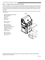
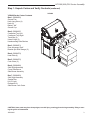
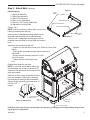
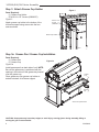
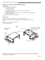
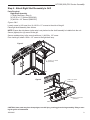
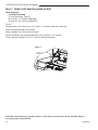
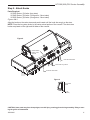
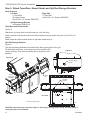
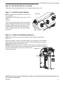
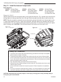
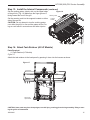
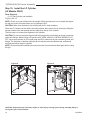
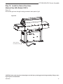
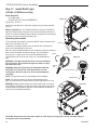
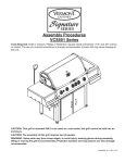
Assembly Procedures
VCS300 Series / VCS400 Series / VCS500 Series
Tools Required: Knife or scissors, Phillips or Robertson (square head) screwdriver, 7/16” and 3/8” wrench
or ratchet. The use of a manual screwdriver is strongly recommended. A power drill may cause damage to
the unit or stripping of the protective coating.
VCS500
VCS400
VCS300
CAUTION: This grill is intended ONLY to be used as a cart model, this grill cannot be built into an
enclosure.
CAUTION: The assembly of this grill requires two (2) people.
WARNING: Some parts may have sharp edges; to avoid injury, wearing gloves during assembly,
lifting or moving the grill is recommended. Protective eyewear and long sleeves are also strongly
20300447
recommended.
VCS Users guide cover
10/09
NOTE: Remove the protective plastic coating from the stainless steel, failure to do so will void the warranty.
20300448 10/09 Rev. 1 En
VCS300/400/500 Series Assembly
Step 1: Unpack Carton and Verify Contents
Use a sharp cutting tool to cut the straps on the packaging and then lift off the carton top. Remove the box
on the top. The sleeve surrounding the barbecue can be removed by lifting it straight up and over the top of
the unit. Compare all contents to the parts list and the carton content lists below. Be careful not to scratch
or damage the finish of the metal parts when removing the protective plastic. Refer to the parts list for fastener detail.
CAUTION: Some parts may have sharp edges; to avoid injury, wearing gloves during assembly is strongly
recommended.
VCS300
VCS300 Series Carton Contents
Box 1 (50004544)
Grease Pan
Knobs (3)
Battery “AAA”
Grease Cup
Box 2 (50004564)
Cook Grate (2)
Box 3 (50004990)
Shelf Right Assembly
Hardware Bag Side Shelves
Condiment Tray Left
Condiment Tray Right
Towel Bar (2)
Utensil Hook (3)
1 3
Box 4 (50004991)
Shelf Left Assembly
Heat Plate (3)
2
4 5 8 CAr216a
VCS300 carton contents
12/08
4 7 2 3 1 10 6 9 CAUTION: Some parts may have sharp edges; to avoid injury, wearing gloves during assembly, lifting or
moving the grill is recommended.
20300448
VCS300/400/500 Series Assembly
Step 1: Unpack Carton and Verify Contents (continued)
VCS400
VCS400 Series Carton Contents
Box 1 (50004562)
Grease Pan
Knob Long Stem (4)
Knob (2)
Battery “AA”
Grease Cup
Box 2 (50004547)
Condiment Tray Left
Condiment Tray Right
Towel Bar (2)
Utensil Hook (3)
Hardware Bag Side Shelves
2
3
1
4
Box 3 (50004871)
Door Accessory Shelf
Bracket Spit Rod Storage (2)
7
Box 4 (50004570)
Heat Plate (4)
Box 5 (50004575)
Cook Grate (3)
5
6
Box 6 (50004990)
Shelf Right Assembly
Cover Side Burner
Side Burner Assembly
Box 7 (50004993)
Shelf Light Assembly
Smoker Box
Kit VC Light
Rotisserie Kit
Side Burner Cook Grate
CAr233
VCS400 2010 carton content
CAUTION: Some parts may have sharp edges; to avoid injury, wearing gloves during assembly, lifting or moving the grill is recommended.
20300448
VCS300/400/500 Series Assembly
Step 1: Unpack Carton and Verify Contents (continued)
2
33
4
1
6
7
5
VCS500 Series Carton Contents
Box 1 (50004551)
Grease Pan
Knob Long Stem (4)
Knob (2)
Battery “AA”
Grease Cup
Box 2 (50004547)
Condiment Tray Left
Condiment Tray Right
Towel Bar (2)
Utensil Hook (3)
Hardware Bag Side Shelves
Box 3 (50004871)
Door Accessory Shelf
Bracket Spit Rod Storage (2)
Box 4 (50004557)
Heat Plate (5)
Box 5 (50004559)
Cook Grate (4)
CAR234
VCS500
2010 cartons
Box
6 (50004990)
Shelf Right Assembly
Cover Side Burner
Side Burner Assembly
Box 7 (50004993)
Shelf Left Assembly
Smoker Box
Kit VC Light
Rotisseries Kit
Side Burner Cook Grate
CAUTION: Some parts may have sharp edges; to avoid injury, wearing gloves during assembly, lifting or
moving the grill is recommended.
20300448
VCS300/400/500 Series Assembly
Step 2: Attach Skirt (Optional)
Parts Required:
(1) Skirt Left Assembly
(1) Skirt Right Assembly
(1) Skirt Front Assembly
(2) Skirt Corner Assemblies
(7) #10-24 x 3/8” Screws (50004268)
(4) Adjustable Leveling Glide
Figure 1
Leveling
Glide
Skirt Right Assembly
Skirt Left Assembly
Skirt Front Assembly
Figures 1 & 2
B157
NOTE: Remove protective coating from corner posts
before proceeding with this step.
Leveling
Glide
Screw-in two (2) adjustable leveling glides into hex
threaded insert provided in front skirt assembly.
Inverted View
Screw-in one (1) adjustable leveling glide into hex
threaded insert provided in left and right skirt assemblies.
Attach left skirt assembly to the unit:
–Loosen one hex bolt from corner post. (Refer to Corner Post
Detail)
–Slide left skirt assembly between bottom panel and
side panel.
–Secure left skirt assembly with two (2) #1024 x 3/8” screws.
–Tighten hex bolt at the back of the
unit.
"
ATTACHLEVELINGGLIDE
Figure 2
Repeat these steps for right side.
NOTE: If you have any problems sliding the
skirt assembly (left or right), loosen four (4)
screws on side panel and lift the side panel to
allow more space.
Slide two (2) skirt corner assemblies into the
front skirt assembly. Slide above assembly
into attached left and right skirt assemblies.
Secure all skirt assembly parts with three (3)
#10-24 x 3/8”
screws.
B213
#10-24 x 3/8”
Screws
Loosen Outer Bolt
at Back Side
Skirt Left
Corner Post/Skirt Detail
Assembly
Skirt Front
Assembly
Skirt Corner Assembly
CAUTION: Some parts may have sharp edges; to avoid injury, wearing gloves during assembly, lifting or moving the grill is recommended.
20300448
B213
VCS300/400/500 Series Assembly
Step 3: Attach Grease Cup Holder
Figure 3
Parts Required:
(1) Grease Cup Holder
(2) #10-24 x 1/2” Screws (50000337)
Figure 3
Attach grease cup holder to the bottom of the
left brace support using screws into the hexserts as shown.
#10-24 x 1/2”
Screws
(50000337)
Grease Cup Holder
B235
Step 3a: Grease Pan / Grease Cup Installation
Parts Required:
(1) Grease Pan
(1) Grease Cup
Figure 3a
Figure 3a
Install grease pan from back side of unit. NOTE:
Be sure the grease tray is positioned with the
opening in the bottom of the grease tray located
over the grease cup.
Grease
Tray
Place grease cup into grease cup holder attached to bottom of left brace support.
"
ATTACHGREASECUPHOL
Grease
Cup
Shown with optional skirt
B159
"
INSTALLGREASETRAYCUP
CAUTION: Some parts may have sharp edges; to avoid injury, wearing gloves during assembly, lifting or
moving the grill is recommended.
20300448
VCS300/400/500 Series Assembly
Parts Required for Steps 4, 5, 6 & 7
Right Side Shelf
Left Side Shelf
(1) Kit Condiment Tray* (50004547) (1) Kit Condiment Tray* (50004547)
(1) Kit Shelf Right** (91D0141) (1) Kit Shelf Left*** (91D0110)
*Kit Condiment Tray (50004547) Contents
(1) Condiment Tray Left
(1) Condiment Tray Right
(2) Towel Bars
(3) Utensil Hooks
**Kit Shelf Right (91D0141) Contents
(1) Shelf Right Assy w/Support Brackets
(1) Cover Side Burner Assy
(1) Side Burner Assembly
***Kit Shelf Left (91D0110) Contents
(1) Shelf Left Assy w/Support Brackets
CAUTION: Some parts may have sharp edges; to avoid injury, wearing gloves during assembly, lifting or moving the grill is recommended.
20300448
VCS300/400/500 Series Assembly
Steps 4 & 5: Right & Left Side Shelf Assembly
Parts Required:
(1) Kit Condiment Tray (50004547)
(1) Condiment Tray Left
(1) Condiment Tray Right
(1) Hardware Bag Side Shelves (for both right and left side shelves)
(1) Kit Shelf Right (91D0141)
(1) Shelf Right Assy w/Support Brackets, Cover and Side Burner Assembly installed
(1) Kit Shelf Left (91D0110)
(1) Shelf Left Assy. w/Support Brackets
Figure 4
Left Side Shelf
Loosen two (2) screws on the support front of the left shelf assembly.
Slide the front condiment tray into the gap between front support and the side panel as
shown.
Tighten the two (2) screws loosened earlier.
Repeat for right side shelf.
Figure 4
Left Side Shelf
Assembly
Right Side Shelf
Right Side Shelf Assembly
(Cover and side burner assembly not shown)
Left Side Shelf
Loosen Screws
From Inside
Loosen
Screws
From Inside
B217
Condiment Tray Right
Condiment Tray Left
"
SHELFASSY
CAUTION: Some parts may have sharp edges; to avoid injury, wearing gloves during assembly, lifting or
moving the grill is recommended.
20300448
VCS300/400/500 Series Assembly
Step 6: Attach Right Shelf Assembly to Grill
Parts Required:
Right Shelf Assembly
(1) Right Shelf Assy. (Step 4)
(4) 1/4-20 x 1Z\x” Screws (50001383)
(2) #10-24 x 1/2” Screws (50000337)
Figures 5 & 6
Loosely screw in (4-5 turns) four (4) 1/4-20 x 1Z\x” screws to the side of the grill.
Place right shelf assembly onto screws.
NOTE: Ensure the side burner ignitor wire is not pinched as the shelf assembly is installed into the unit.
Secure (tighten) four (4) screws to the grill.
Secure condiment tray to the console with one (1) #10-24 x 1/2” screw.
From inside grill, attach 10-24 x 1/2” screw to the right shelf assy.
Figure 5
1/4-20 x 1Z\x” Screw
(50001383)
B221
Figure 6
B221
attach right shelf
10/07
10-24 x 1/2” Screw
(50000337)
10-24 x 1/2” Screw
(50000337
B222
CAUTION: Some parts may have sharp edges; to avoid injury, wearing gloves during assembly, lifting or moving the grill is recommended.
20300448
"
SECURERIGHTSHELF
VCS300/400/500 Series Assembly
Step 7: Attach Left Shelf Assembly to Grill
Parts Required:
Left Shelf Assembly
(1) Left Shelf Assy. (Step 5)
(4) 1/4-20 x 1Z\x” Screws (50001383)
(2) #10-24 x 1/2” Screws (50000337)
Figure 7
Loosely screw in (4-5 turns) four (4) 1/4-20 x 1Z\x” screws to the side of the grill.
Place left shelf assembly onto screws.
Secure (tighten) four (4) screws to the grill.
Secure condiment tray to the console with one (1) #10-24 x 1/2” screws.
From inside grill, attach 10-24 x 1/2” screw to the left shelf assy.
Figure 7
#10-24 x 1/2” Screws
(50000367)
B229b
B229b
attach left shelf
10/07
CAUTION: Some parts may have sharp edges; to avoid injury, wearing gloves during assembly, lifting or
moving the grill is recommended.
10
20300448
VCS300/400/500 Series Assembly
Step 8: Attach Knobs
Parts Required:
VCS300 Series: (3) Knobs (long stem)
VCS400 Series: (5) Knobs (3 long stem, 2 short stem)
VCS500 Series: (6) Knobs (4 long stem, 2 short stem)
Figures 8 & 9
Align the knobs on the valve stems and push inward until the knob sits snugly on the stem.
NOTE: Place the long stem knobs in the center raised portion of the console. The short stem
knobs are placed on the right and left sides of the console.
Figure 8
Center Raised
Portion of the
Console
Knob with Short Stem
Knobs with Long Stems
Knob with Short Stem
B234a
Figure 9
Long Stem
Knob
B234a
attach knobs
12/08
1/4”
(6 mm)
"
CONTROLKNOB
CAUTION: Some parts may have sharp edges; to avoid injury, wearing gloves during assembly, lifting or moving the grill is recommended.
20300448
11
VCS300/400/500 Series Assembly
Step 9: Attach Towel Bars, Utensil Hooks and Spit Rod Storage Brackets
Parts Required
Left Side
(1) Towel Bar
(3) Utensil Hooks
(4) #10-24 x 1/2” Screws (50000337)
Right Side
(1) Towel Bar
(4) #10-24 x 1/2” Screws (50000337)
Spit Rod Storage Bracket
(2) Brackets (50004310)
Towel Bars and Utensil Hooks
Figure 10
Slide three (3) utensil hooks into the towel bar. (Left side only)
Attach towel bar with utensil hooks to left side condiment tray as shown using four (4) #10-24 x 1/2”
screws.
Attach towel bar without utensil hooks to right side condiment tray.
Spit Rod Storage Brackets
Figure 11
The spit rod storage brackets are located on the back upper panel of the grill.
Tilt the bracket as shown, so the larger end of the bracket will fit
into the opening. Then slide the bracket down. Repeat for both
brackets.
Figure 11
Figure 10
Spit Rod Storage
Bracket
B224
#10-24 x
1/2” Screws
(50000337
Towel
Bar
"
Spit
Rod
SPITRODSTORAGE
Storage
Utensil Hooks
B223a
Rear View
Shown with optional skirt
B225
B223a
CAUTION: Some parts may have sharp edges; to avoid injury, wearing gloves during assembly, lifting or
towel
bars
moving the grill
is recommended.
12
10/07
"
SPITRODSTORAGE
20300448
VCS300/400/500 Series Assembly
Step 10: Attach Side Burner Assembly
Follow Side Burner Assembly Instructions to assemble side burner to unit.
Step 11: Install the Ignitor Battery
NOTE: VCS300 Series require one (1) “AAA” battery. (Included)
VCS400 and VCS500 Series require one (1) “AA”
battery.
Figure 12
Figure 12
Unscrew the ignition button from the console and
insert the appropriate battery into the housing by
placing the positive side of the battery first. Then
screw the ignition button back into the console.
B214
Check for sparks under each main burner before
proceeding.
Step 12: Install the Backlighting Batteries
NOTE: Eight (8) “AA” batteries are required for all grill models. (Not included)
"
)NSTALLBATTERY
Figures 13
Remove the battery case from the battery holder. Insert the eight (8) “AA” batteries.
Attach battery case to back light wire connection. Reinstall battery case in battery
holder with back light connector on the top.
WARNING: Replacing the battery incorrectly might result in an explosion. Replace
the battery only with the same or equivalent type recommended by the manufacturer.
Dispose of used batteries according to your local enviFigure 13
ronmental guidelines.
Battery
Case
B238
CAUTION: Some parts may have sharp edges; to avoid injury, wearing gloves during assembly, lifting or mov"A
ing the grill is recommended.
20300448
BATTERYCASE
13
VCS300/400/500 Series Assembly
Step 13: Install the Internal Components
Parts Required:
VCS300 (3) Sear Plates
VCS400
Series
(2) Cooking Grates
Series
(1) Warming Rack
(4) Sear Plates
VCS500
(3) Cooking Grates
Series
(1) Warming Rack
(1) Smoker Box Assy
(5) Sear Plates
(4) Cooking Grates
(1) Warming Rack
(1) Smoker Box Assy
Figures 14, 15 & 16
Carefully place each of the sear plates side by side inside the barbecue. (Fig. 14) Make sure the semicircular finger groove is facing toward the front of the grill. Each sear plate rests just above each burner tube.
NOTE: Place the smoker box assembly on any sear plate by laying the bracket over the sear plate so the
‘z’ ends of the bracket fit into the ‘z’ slots of the sear plate. Slide the smoker box assembly back into the
locked position. (Fig. 15) Continue placing the remaining sear plates. The smoker box may be left in place
when not being used. CAUTION: Only add wood chips to the smoker box when grill is cool.
Figure 14
Figure 15
Sear Plate
‘Z’ End
Smoker Box
B215
Sear Plate
B226
"
SMOKERBOX
To produce more smoke and prevent fast burning, pre-soak the wood chips in a separate
bowl of water for at least 20 minutes.
Cooking Tips - Smoker Box
•
• To add wood chips before cooking, fill the smoker box with your choice of flavored chips
(remove wood chips from water first). The amount and type of wood you use is entirely up
to"A
you. Once the box is filled with the desired amount, close the lid and place the cooking
)NSTALLSEARPLATES
grids
in the proper position on the grill.
• Tips:
Small wood chips work best inside the wood chip box.
• Allow grill to heat up before placing your food on the grill. This will allow time for the wood
chips to begin to smoke.
• Do not use resinous woods such as pine or plywood. These will produce an unpleasant
flavor.
• Do not try to add more wood chips while cooking. It is recommended that you allow grill to
cool before replacing wood chips or handling the cooking grates which may still be hot.
CAUTION: Some parts may have sharp edges; to avoid injury, wearing gloves during assembly, lifting or
moving the grill is recommended.
14
20300448
VCS300/400/500 Series Assembly
Step 13: Install the Internal Components (continued)
Set the cooking grates, side by side, on the upper ledge
of the grill tub. (Fig. 16) Make sure the finger groove is
facing toward the front of the grill.
Figure 16
Warming Rack
Set the warming rack into the supports located on either
side of the rear lid.
Cooking
Grates
CAUTION: Do not attempt to turn the cooking grates
over while the grill is in use and the grates are hot. Doing so could result in severe burns and other injuries.
B216
Step 14: Attach Tank Retainer (All LP Models)
Parts Required:
(1) Tank Retainer (LP Models)
Figure 17
Attach the tank retainer to the back panel by pressing it down into the bosses
B216 as shown.
install cooking grates
10/07
Figure 17
Bosses
Tank
Retainer
Shown with
optional skirt
B241a
CAUTION: Some parts may have sharp edges; to avoid injury, wearing gloves during assembly, lifting or moving the grill is recommended.
B241a
20300448
tank retainer
15
VCS300/400/500 Series Assembly
Step 15: Install the LP Cylinder
(LP Models ONLY)
Parts Required:
(1) LP Gas Cylinder (not included)
Figures 18 & 19
NOTE: Check your User’s Manual for the cylinder filling requirements, how to attach the regulator and how to test for leaks before you try lighting the grill.
CAUTION: Make sure the hose is not touching any hot or sharp surfaces.
Place the LP Cylinder into the hole in the bottom panel. Next secure it from moving by lifting the
cylinder retainer wire and latching the bent edge over the lip of the cylinder.
The final step is to connect the regulator to the cylinder.
CAUTION: Do not turn on/ignite the grill until after performing a leak check at all gas connection
points and fittings. With the main LP cylinder valve OPEN, and ALL CONTROL KNOBS FULLY
OFF, use a spray solution of 50% liquid soap and 50% water onto all gas connection points and
fittings. The formation of bubbles indicates an air leak that must be repaired and verified with
this leak test before the grill is ignited.
NOTE: Ensure all plastic coatings have been removed from all stainless steel parts before using
the grill.
Figure 18
Figure 19
B228a
B227a
B227a
B228a
tank in place
12/08
CAUTION: Some
installparts
tankmay have sharp edges; to avoid injury, wearing gloves during assembly, lifting or
moving the grill
is
recommended.
12/08
16
20300448
VCS300/400/500 Series Assembly
Step 16: Install the Natural Gas Hose
(Natural Gas (NG) Models ONLY)
Figure 20
Run natural gas hose through bushing provided in back panel of grill.
Figure 20
B240a
Shown with Optional Skirt in Place
"A
NATURALGASHOSE
CAUTION: Some parts may have sharp edges; to avoid injury, wearing gloves during assembly, lifting or moving the grill is recommended.
20300448
17
VCS300/400/500 Series Assembly
Step 17: Install Shelf Light
(VCS400, VCS500 Series Only)
Parts Required:
(1) Cook Light
(3) #10-24 x 1/2” Screws (50000337)
Figure 21
Figures 21, 22 & 23
Attach the cook light to the side shelf using three (3) screws provided.
(Fig. 21)
Battery Installation (3 “AA” alkaline batteries required, not included.)
Open the battery cap by turning the cap counterclockwise as shown in
Figure 22. Insert the batteries into the battery compartment according to
the layout in Figure 22. Replace battery cap.
Operating Instructions
To turn the light ON and OFF, press the ON/OFF button located on the
back of the cook light. (Fig. 22)
Screws
To adjust the cook light, simply move the flexible arm as desired to
achieve the best lighting for your task.
After use, allow the light and grill to cool completely. Place the light face
down on the shelf after use and for storage. (Fig. 23) Replace
To Open
the grill cover. If a grill cover is not used, the light should be
removed when not in use as rain, snow, etc. could damage the
light.
WARNING: The light may get hot when in close proximity to
the grill surface. Do not touch the light lens when in operation. Allow it to cool.
WARNING: Keep the light away from flammable materials.
Flexible
Arm
CAUTION: Do not move the cook light directly over the
cooking area when the grill is on, as this may damage the
cook light.
NOTE: The light will not work until the batteries are installed.
NOTE: For optimum battery life and to avoid damage to the
light, we recommend you retract and turn off the light when not in use.
WARNING: Replacing the battery incorrectly might result in an explosion. Replace the battery only with the same or equivalent type recommended by the manufacturer. Dispose of used batteries according to
your local environmental guidelines.
B208a
Battery Cap
Figure 22
"A
ATTACHSIDELIGHT
Cook Light Handle
ON/OFF Button
B209
Figure 23
"
COOKLIGHT
B232
CAUTION: Some parts may have sharp edges; to avoid injury, wearing gloves during assembly, lifting or
moving the grill is recommended.
18
20300448
VCS300/400/500 Series Assembly
NOTES
CAUTION: Some parts may have sharp edges; to avoid injury, wearing gloves during assembly, lifting or moving the grill is recommended.
20300448
19
VCS300/400/500 Series Assembly
MHSC
149 Cleveland Drive • Paris, Kentucky 40361
www.mhsc.com
CAUTION: Some parts may have sharp edges; to avoid injury, wearing gloves during assembly, lifting or
moving the grill is recommended.
20
20300448