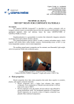
1
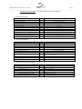
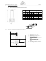
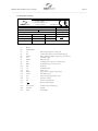
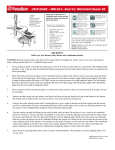
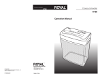
Filterpump Nauti User Manual Issue 2 23/10/08
Page 1
_____________________________________________________________________________
ROTORFLUSH FILTERPUMPS
Models N9316 –N9916
USE AND MAINTENANCE INSTRUCTION MANUAL
TO BE KEPT BY THE USER
1.
MANUFACTURER AND FILTERPUMP IDENTIFICATION DATA (as per EEC98/37 p. 1.7.4a)
1.1.
Manufacturer Data
Rotorflush Filters
Langmoor Manor
Charmouth
Bridport
Dorset
DT6 6BU
England
Telephone:
+44 (0) 1297 560229
Fax:
+44 (0) 1297 560110
Email:
[email protected]
1.2
Filterpump Data
Description: Submersible Filterpump Models. N5616 N9316, N9416, N9516, N9616, N9716, N9816 and
N9916
2.
TECHNICAL ASSISTANCE INFORMATION
If a malfunction of the Filterpump is not covered in the TROUBLESHOOTING table (Section 15) contact Rotorflush
Filters at the above address.
3.
INTRODUCTION
This publication contains all necessary information and instructions for the use and maintenance of your Rotorflush
Filterpump.
Follow the advice given to ensure correct operation and optimum performance of the Filterpump. For any other
information, please contact Rotorflush Filters
THESE INSTRUCTIONS AND ILLUSTRATIONS ARE SUBJECT TO COPYRIGHT AND MUST NOT BE COPIED
IN WHOLE OR IN PART
Filterpump Nauti User Manual Issue 2 23/10/08
Page 2
_____________________________________________________________________________
4.
CONTENTS
1.
2.
3.
4.
5.
6.
7.
8.
9.
10.
11
Manufacturer and Machine Identification Data
Information on Technical Assistance
Introduction
Contents
General Safety Warnings
5.1.
Preventive measures to be taken by the user
5.2.
Significant protection and precautions
Description
6.1.
General description
6.2.
Technical and construction features
Technical Data Card
7.1.
Pump technical data
7.2.
Motor technical data
7.3.
Filter technical data
Contemplated and Non-contemplated Use
8.1.
Contemplated conditions of use
8.2.
Non-contemplated conditions of use
Handling and Transport
9.1.
Unpacking
9.2.
Handling and De-installing
9.3.
Transport
Preparations for use
10.1 General information
10.2 Electrical connections
10.3 Checking the Direction of Rotation (3 phase models)
Installation
11.1 Fixed installation
11.2 Temporary installation
12 Assembly and Disaassembly
13 Adjusting and registering
14 Use and Startup
14.1 Starting
14.2 Version with Floating switch
14.3 Version without floating switch
15 Maintenance and repairs and troubleshooting
16 Technical information
16.1 Dimensions and packing weights
16.2 Diagram for installation minimum distances
16.3 Rating plate example
17 Information on airborne noise
18 Waste disposal
Filterpump Nauti User Manual Issue 2 23/10/08
Page 3
_____________________________________________________________________________
5.
GENERAL SAFETY WARNINGS
FAILURE TO OBSERVE THESE WARNINGS AND/OR ANY TAMPERING WITH THE FILTERPUMP
EXEMPTS ROTORFLUSH FILTERS FROM ALL RESPONSIBILITY IN THE EVENT OF PERSONAL INJURY
OR DAMAGE TO EQUIPMENT OR PROPERTY AND/OR TO THE FILTERPUMP
Read this manual carefully and check to ensure that the Filterpump has been properly installed and connected in
accordance with relevant safety standards before starting the Filterpump.
There are no RESIDUAL RISKS with Rotorflush Filterpumps.
No particular technical skills are required to use Rotorflush Filterpumps.
No personal safety devices (precaution devices) are required to use Rotorflush Filterpumps.
5.1.
Preventive Measures to be Taken by the User
d)
e)
f)
g)
h)
5.2.
a)
The user must specifically comply with all the accident prevention regulations in
force in the respective countries in which the Filterpump is being used; the
indications given in Section 7 must be scrupulously followed.
b)
c)
During operation make sure that nobody is in the water
Before undertaking any repairs or maintenance to the Filterpump, isolate the
electricity supply by removing the plug from the socket and/or turning off the
switch (if provided). This will prevent accidental starting which could cause
personal injury or damage to equipment or property.
Any maintenance operation, installation or moving the Filterpump with the electrical system live may
cause serious injury and could prove fatal.
During operation, avoid moving the Filterpump.
Before using the Filterpump, always check that the cable and all electrical devices are in perfect
working order.
When starting up the Filterpump (by turning on the switch, if provided, or by inserting the plug in the
socket) ensure (i) you do not have wet hands (ii) you are not standing in water and (iii) you are not
barefoot.
The user must not carry out under his/her own initiative any operations or tasks not contemplated in
this manual.
Significant Protection and Precautions
(as per EEC 98/37 p. 1.1.2 and 1.7.2; EN 292-2 p.5).
Rotorflush Filterpumps are designed so that all moving parts are shrouded by protective casings. Rotorflush
Filter declines all responsibility in the event of injury or damage caused as a result of tampering with these
devices.
Each lead or live part is electrically insulated to earth; there is also a further
safety device in that the accessible conductive parts are connected to an
earth lead so that the parts within reach cannot become dangerous in the
event of failure of the principal insulation.
Filterpump Nauti User Manual Issue 2 23/10/08
Page 4
_____________________________________________________________________________
6.
DESCRIPTION
6.1.
General Description
Rotorflush N Series Filterpumps are all similar from the functional and constructive point of view; the only
differences are the following:
power
flow rate
head
electric power supply (single phase or three phase)
weight
dimensions
Rotorflush Filterpumps are used for handling water containing total suspended solids not greater than 2,000
mg/litre dry weight at temperatures up to 40°C (Section 7.1). Unwanted solids are separated by a self-cleaning
filter which is continuously backwashed with filtered water pumped though a dual-headed rotor by a secondary
impeller mounted on an extended impeller shaft attached to the pump.
Thanks to their small bulk and ease of transport, they may be used for fixed or temporary installations, with or
without automatic start.
Rotorflush Filterpumps are designed for long life and constant performance if used according to the instructions
given in Sections 8 and 15.
6.2.
Technical and Construction Characteristics
Rotorflush Filterpumps are designed and built to the following design and construction standards:
Machine 98/037/EEC; EN292 standard
Low Voltage 73/23/EEC and relative additions EN60335-1 and EN 60335-2-41 standards
Electromagnetic Compatability 89/336/EEC and relative additions EN50081-1 and 2 standards
Filterpump Nauti User Manual Issue 2 23/10/08
Page 5
_____________________________________________________________________________
7. TECHNICAL DATA CARD (as per EEC 98/37 p.1.1.2 and 1.7.2; EN 292-2 p.
7.1 Pump Technical Data
Maximum temperature of pumped fluid
°C
40
Maximum immersion depth…….
m
= (length of electric cable-2) to a maximum of 20m.
Maximum total head
m
See plate on Filterpump
Length and type of power cable
m
10 (20) H07 RN-F
Maximum working pressure kPa
(bar)
1500 (15)
Type of impeller
Closed
Type of seal on shaft
Duplex seal with oil-lubricated intermediate chamber
Type of bearing
Shielded ball bearing
Delivery diameter
Threaded Rp 1 1/4
Impeller material
Stainless steel
Stage material
Stainless steel
Diffusers material
Stainless steel
Seal holder material
Stainless steel
7.2 Motor Technical Data
Power
kW
See Plate on Pump
Type
Dry submerged
Polarity
No.
2
Insulation class
F
Degree of protection
IP68
Type of duty
Continuous
Phase - frequency - voltage
See plate on Filterpump
See Para 10.1 for voltages and equivalent tolerances
Overpower protection
Single phase up to 1.1kW included over 1.1 kW and three
phase to be provided by user
Capacitor
External
Motor structure material
Stainless steel
Shaft material
Stainless steel
7.3 Self-cleaning Filter Technical Data
Filter Area
474 cm2
Filter Mesh
Monofilament polyester either 50,100,200 or 300 microns
Materials: Filter cage
stainless steel
Backwash rotor
Acetal Copolymer
Rotor thrust bearing
Silicon Carbide
Rotor impeller
AISI304 stainless steel
Rotor impeller extension shaft
AISI304 stainless steel
Filterpump Nauti User Manual Issue 2 23/10/08
Page 6
_____________________________________________________________________________
8.
9.
CONTEMPLATED AND NON-CONTEMPLATED USE
WARNING
Failure to respect the prescribed limits constitutes a situation of use that is technically improper and may endanger the
safety of persons and thus EXEMPTS ROTORFLUSH FILTERS FROM ANY RESPONSIBILITY IN THE EVENT OF
ACCIDENTS TO PERSONS OR DAMAGE TO EQUIPMENT OR PROPERTY AND/OR TO THE FILTERPUMP,
THEREBY RENDERING THE GUARANTEE INVALID.
8.1
Contemplated Conditions of Use
Rotorflush Filterpumps are suitable for pumping water, non-aggressive and compatible with materials used to
construct the pump. Max density 1.1 kg/dm3 with a total suspended solids loading not exceeding 2000mg/litre
dry weight. Oily/fatty/sticky solids will reduce filter performance. They can be used with pressurisation units.
Use the Filterpump in keeping with its technical characteristics (Section 7).
8.2
Non-Contemplated Conditions of Use
Rotorflush Filterpumps must not be installed in swimming pools, garden ponds and similar environments where
and when people are in the water. For pumping fluids having a total suspended solids loading of more than
2,000 mg/litre dry weight, Rotorflush Filterpumps must never be run without water.
HANDLING AND TRANSPORT
(as per EEC 98/37 p. 1.7.4.a; EN 292-2 p.5 1.1.a)
9.1
Unpacking
Check that there are no breakages or severe dents in the packing; if there are, point this out immediately to the
person who delivers the material. After removing the Filterpump from the package, check that it has not suffered
any damage during transit; if damage is found, inform the dealer within 8 days of delivery. Check that the
specifications stated on the plate of the Filterpump are the same as you requested in your order.
9.2
Handling and De-installing
WARNING
FAILURE TO FOLLOW THESE INSTRUCTIONS MAY CAUSE
THE FILTERPUMP TO FALL AND SUFFER SEVERE DAMAGE.
NEVER UNDER ANY CIRCUMSTANCES USE THE POWER
CABLE TO LIFT OR DRAG THE FILTERPUMP.
To handle or de-install the Filterpump you must:
remove the plug from the power socket and/or switch off the switch, if provided;
roll up and hold the electric power cable in your hand;
lift the Filterpump and the delivery pipe.
If the Filterpump is set up for fixed applications, perform the following operations before handling it:
9.3
-
remove the plug from the power socket and/or switch off the switch, if provided;
-
unscrew any clamps and remove the delivery pipe;
roll up and hold the electric power cable in your hand;
lift the Filterpump and the delivery pipe.
Transport
The Filterpump is packed in a cardboard box for transport; as its total weight and bulk are not excessive (fig 1),
transport presents no difficulties. However, check the gross weight.
Filterpump Nauti User Manual Issue 2 23/10/08
Page 7
_____________________________________________________________________________
10.
PREPARATION FOR USE
(as per EEC 98/37 p.1.7.4.a, EN 292-2 p.5.1.3).
10.1 General information
Before beginning to work on the electrical pump, make sure that you have disconnected the electricity from the power supply
mains and that it cannot be accidentally reconnected.
The voltage variation allowed +/- 5% (single phase 220-240 V, 3-phase 380-415 V)
10.2 Electrical Connections
Connections must only be performed by an authorised electrician in compliance with the law in force. Verify that the data
on the name plate match the nominal values for the power line. Make the connection after verifying the existence of a
working grounding circuit.
It is the installers responsibility to perform the connection in compliance with regulations in force in the country of
installation.
Single phase versions will be supplied with an electrical panel that includes a capacitor.
In the single phase versions up to 1.1kW included, the motor is protected against overload by a thermal device (overload
cut-out) inserted in the winding.
Single phase 1.5-2.2kW power versions need external protection (bimetal trigger overload cut-out) with intervention time
calibrated to:
•
Less than 30 minutes with 1.5 times IN
•
From 7 to 20 seconds with 2 times IN
IN
= maximum value of current shown on the name plate
The 3-phase versions need external protection (rapid disconnect magnetic overload cut-out) with intervention time calibrated
to:
•
Less than 10 seconds with 5 times IN
•
Less than 10 minutes with 1.5 times IN
IN
= maximum value of current shown on the name plate
The installation of a differential switch is highly recommended
10.3 Checking the Direction of Rotation (Three Phase only)
After connecting the power supply, the direction of rotation can be inverted in the three phase versions; in this case
performance will be significantly lower than the nominal values and will cause substantial damage to the Filterpump if
run in the wrong direction for more than a few seconds and will invalidate any guarantee.
To verify a correct connection, proceed as follows:
Start the pump before it is installed. By reaction, it must tend to rotate (“kick”) in an ANTICLOCKWISE viewed from above (discharge end).
CAUTION! This operation will be performed dry and must not last more than a few seconds.
Filterpump Nauti User Manual Issue 2 23/10/08
Page 8
_____________________________________________________________________________
11. INSTALLATION
(as per EEC 98/37 p. 1.7.4.a; EN 292-2 p.5.1.1b)
WARNING
TO LIFT OR LOWER THE FILTERPUMP, USE A ROPE FIXED TO THE EYELETS; NEVER USE THE
ELECTRIC POWER CABLE.
Before beginning to work on the electrical pump make sure that you have disconnected the power supply from the power
supply mains and that it cannot be accidentally reconnected.
The installation of the electrical pump can involve a certain amount of complexity. For this reason, it must be performed by
competent and authorised installers.
The Filterpump must be protected by the installation of dry run protection. If the filter blocks because of high
levels of solids in the water or for some other reason the pump will run without water. This will cause damage to
the pump and will invalidate any guarantee. Dry run protection can be by monitoring the power factor of the
motor or by monitoring the flow/pressure from the delivery pipe.
Rotorflush can provide dry run protection for its pumps and it is strongly advised that the correct protection is
purchased from Rotorflush Filters
The Delivery Pipe
The diameter of the delivery pipe depends on the flow rate and pressure available at the points of use. For installations
with long lengths of delivery pipe, friction loss can be reduced by using a pipe diameter larger than the discharge outlet of
the pump. It is advisable to install a check valve after the discharge outlet to avoid dangerous water hammers in the event
the electrical pump should stop suddenly. Do not use excessive force when screwing the pipe to the discharge outlet in
order to avoid damage. The electrical pump can be installed for use with either a metal pipe ( which can be used to support
the pump|) or flexible tubing. In the latter case the electrical pump must be supported by a cable made of a material with
long lasting resistance, passing through the eyelets at the top of the pump. Fix the power cable to the delivery pipe using
suitable straps.
CAUTION! Do not underestimate the risk of drowning if the installation must be performed in a well of a certain depth.
Make sure there is no danger of toxic vapours or harmful gases in the work atmosphere.
11.1 Fixed Installation ( We strongly recommend that the pump is fitted with dry run protection, so that if the filter blocks
for any reason or there is insufficient water the pump is automatically stopped to prevent damage from dry running)
11.1.1 The Filterpump may be installed upright or horizontally although the self-cleaning filter will work better in the upright
position
11.1.2 The Filterpump should be fully submerged if possible although this is not necessary except for frost protection. The
Filterpump will operate continuously if at least 350mm of the filter unit and suction end of the pump are submerged in
water at a temperature of less than 40°C.
There must be a gap of at least 100mm around and underneath the filter unit, although there is no need for a gap under the
Filterpump when operated in the upright position if there is a flow of fluid past the filter pump to take detritus away from
the screen (e.g. when installing in a flowing river or flume the filter unit at the suction end of the Filterpump) at all times
to allow solid particles to fall or be washed clear of the filter screen. Due allowance must the made to allow for any buildup of solids underneath the filter and any detritus, sludge etc must be removed from time to time to ensure this does not
come within 100mm of the filter.
When lowering the Filterpump into a well or tank, ensure that it is at least 100mm above the bottom.
Be careful with the power cable when lowering the Filterpump. It is advisable to tie the power cable to the delivery pipe
every two or three metres.
11.1.3.1 When positioning the Filterpump, observe the minimum required distances (fig. 2) from walls, from the sides of the drain,
tank or other location, so as to allow functioning, use and maintenance operations in safe conditions (as per EN 292-2
p.5.5.1.b).
11.1.3.2 It is recommended that G 1¼" rigid pipes (metal or plastic) be attached to the Filterpump with clamps of a suitable size.
11.1.3.3 Anchor the pipes to the edge of the basin or tank with a pipe clamping bracket.
11.1.3.4 If there is the need to install a non-return valve onto the delivery pipes, make sure it is placed away from the Filterpump
filter screen to avoid priming problems when first starting or after empting.
Filterpump Nauti User Manual Issue 2 23/10/08
Page 9
_____________________________________________________________________________
11.2
Temporary Installation (for Temporary Use)
11.2.1.1 The Filterpump may be installed upright or horizontally. (As above)
The Filterpump should be fully submerged if possible (as above) but it will operate continuously if at least 350mm of the
filter unit and suction end of the pump are submerged in water at a temperature of less than 40°C.
11.2.1.2 There must be a gap of at least 100mm around and underneath the filter unit, although there is no need for a gap under the
Filterpump when operated in the upright position if there is a flow of fluid past the filter pump to take detritus away from
the screen( e.g. when installing in a flowing river or flume at the suction end of the Filterpump) at all times to allow solid
particles to fall or be washed clear of the filter screen. Due allowance must the made to allow for any build-up of solids
underneath the filter and any detritus, sludge etc must be removed from time to time to ensure this does not come within
100mm of the filter.
11.2.1.3 When lowering the Filterpump into a well or tank, ensure that it is at least 100mm above the bottom.
11.2.1.4 Be careful with the power cable when lowering the Filterpum. It is advisable to tie the power cable to the delivery pipe
every two or three metres.
11.2.1.5 When positioning the Filterpump, observe the minimum required distances (fig. 2) from walls, from the sides of the drain,
tank or other location, so as to allow functioning, use and maintenance operations in safe conditions (as per EN 292-2
p.5.5.1.b).
11.2.1.6 It is recommended that G 1¼" rigid pipes (metal or plastic) be attached to the Filterpump with clamps of a suitable size.
11.2.1.7 If there is the need to install a non-return valve onto the delivery pipes, make sure it is placed away from the Filterpump to
avoid priming problems when first starting or after empting.
12
ASSEMBLY AND DISASSEMBLY (as per EEC 98/37 p.1.7.4.a).
The basic Filterpump has no separate parts or accessories, so no assembly is required for installation. If the Filterpump is
to be used with the Rotorflush Valve Control System, the assembly instructions provided with the Control Valve system
must be followed.
The user must not attempt to disassemble any other component not covered in these instructions and should
contact Rotorflush Filters for advice if any further disassembly is required.
FAILURE TO COMPLY WITH THIS RULE RENDERS THE GUARANTEE INVALID.
Filterpump Nauti User Manual Issue 2 23/10/08
Page 10
_____________________________________________________________________________
13. Adjusting and Registering
(as per EEC 98/37 p.1.7.4.a; EN 292-2 p.5.5.1.d)
The only thing that needs checking once installation is complete is the length of the cable with float (in versions
that have one) with respect to the minimum and maximum water level .
14. USE AND START-UP (as per EEC 98/37 p.1.7.4.a; EN 292-2 p. 5.5.1.d)
The water level must never be lower than the filter screen, even when the pump is not being used. If you fail to observe
this, the Filterpump will run out of water and you will have great difficulty starting the Filterpump again.
14.1
Starting
Never switch on the Filterpump until it is placed and installed in its final operational
position. It is possible to have leakage of the Filterpump oil into the pumped liquid;
however, this is not harmful to health.
14.2
Version With Floating Switch
To start up the Filterpump, connect the plug and/or turn on the switch. The Filterpump will start automatically as
soon as the water level, regulated by the floating switch, reaches the minimum level. The performance of the
floating switch has been designed by the manufacturer to assure a minimum immersion level in the OFF
position.
14.3
Version Without Floating Switch
To start up the Filterpump, connect the plug and/or turn on the switch. When the water level reaches the
minimum level (fig. 2), disconnect the plug and/or turn off the switch.
Filterpump Nauti User Manual Issue 2 23/10/08
Page 11
_____________________________________________________________________________
15. MAINTENANCE AND REPAIRS
(as per EEC 98/37 p.1.6; EN 292-2 p.5.5.1.e)
BEFORE CARRYING OUT ANY MAINTENANCE OPERATIONS,
DISCONNECT THE PLUG AND/OR SWITCH OFF.
FOR ANY REPAIR JOBS DURING THE GUARANTEE PERIOD, THE USER
MUST CONTACT ROTORFLUSH FILTERS
FAILURE TO OBSERVE THIS RULE RENDERS THE GUARANTEE INVALID.
AFTER THE GUARANTEE PERIOD, ALL MAINTENANCE OPERATIONS,
To ensure correct functioning and long life of the Filterpump, the Rotorflush filter unit should be inspected and cleaned
every two months. The amount of cleaning required will depend on the liquid being pumped in some instances more
frequent manual cleaning of the filter screen may be required, for example where biological growth occurs on the filter
screen or oily/fatty deposits are found to build up on the filter screen) This is the only maintenance required by the
Filterpump.
Check the condition of the electric power cable; if it is damaged, contact the dealer or Rotorflush Filters to have it
replaced.
Troubleshooting
TYPE OF FAULT: The pump does not work (the motor does not turn over)
CAUSE
REMEDY
No electric power
Check the contactor on the electric line
Plug not inserted
Check power connection to the line
Automatic switch has tripped
Reset the switch and check the cause
Float blocked
Check that the float reached ON level
Thermal protection has tripped (single phase) up to 1.1kW
This resets automatically
Protection fuses are burnt out (three-phase)
Replace the fuses with same type
Faulty motor or capacitor
Contact Rotorflush Filters
TYPE OF FAULT: The pump does not work (the motor turns over)
CAUSE
REMEDY
Intake filter blocked
Cleans the filter
Non-return valve blocked
Clean the valve and check its operation
The pump does not start up
Check minimum water level
Check function of delivery gate valve
Hole in filter screen causing pump to block with detritus
Return to Rotorflush Filters for repairs
TYPE OF FAULT: The pump works at a low flow rate
CAUSE
REMEDY
Dirty deliver pipe
Clean pipe
Clogged filter screen
Clean, if continues to be a problem, fit control valve (available from
Rotorflush Filters)
Dirty Impellers
Check filter screen for damage. If damaged contact Rotorflush Filters
for replacement screen)
Non-return valve blocked
Clean the valve and check its operation
Water level too low
Switch off the pump
Wrong direction of rotation
Check the direction of rotation (three-phase only, section 10.3)
Wrong supply voltage
Feed the pump with the voltage indicated on the rating plate
TYPE OF FAULT: The pump stops after brief periods of operation (tripping the thermal protection)
CAUSE
REMEDY
Liquid temperature too high
The temperature exceeds the technical limits of the pump
Internal defect
Contact Rotorflush Filters
Filterpump Nauti User Manual Issue 2 23/10/08
Page 12
_____________________________________________________________________________
16.
TECHNICAL INFORMATION
16.1
Diagram of Filterpump Dimensions, Packing and Weights
MOD
EL
DIMENSION
S
(mm)
H
W
PACKING
(mm)
WEIGHT
(Kg)
X
Y
Z
Single
Phase
Three
phase
650
215
300
260
980
20.7
-
N9416
730
215
300
260
980
23.7
21.2
N9516
760
215
300
260
980
25.7
24.2
N9616
790
215
300
260
980
26.2
24.7
N9716
820
215
300
260
980
-
26.7
N9816
850
215
300
260
980
-
27.2
880
215
300
260
980
-
27.7
N9316
N9916
X
Fig1
Z
Y
16.2
Diagram for Installation with Minimum Functional Distances
CLAMP
A
100mm min gap to side of tank
B
100mm min gap to top of sediment or
detritus at bottom of tank
C
With automatic float switch:
450mm minimum immersion from bottom
of filter.
Without automatic float switch:
250mm minimum immersion from bottom
of filter.
C
D
D
A
B
Fig 2
If used with automatic float switch allow
600mm min gap to side of tank
Filterpump Nauti User Manual Issue 2 23/10/08
Page 13
_____________________________________________________________________________
16.3 Rating Plate Example
ROTORFLUSH FILTERS
Langmoor Manor
Charmouth DT6 6BU UK
+44 (0)1297 560229
TYPE
MADE IN UK
(1)
Q
(3)
l/min.
V~
(2)
H
(4)
(6)
P2
(8) kW
HP
P1
(12) kW
Phase
(15)
ΜF
Vc
Ins.C. F (19) S1
(9)
Hz
(10)
(13)
Min
(14)
(16)
Weight (20) Kg
IP
(17)
P/N
(21)
Hmax
(5)
m
Hmin
(7)
m
A
(11)
__
(18)
m
(1)
Model
(2)
Serial Number
(3)
"Q"
Min and max capacity of duty point
(4)
"H"
Total head in relation to min and max capacity
(5)
"Hmax"
Max total head (usually corresponds to the shut-off
(6)
"V~"
Nominal voltage
(7)
"Hmin"
Min total head
(8)
"P2"
Nominal power of the motor (shaft power)
(9)
"HP"
Nominal horse power of the motor
(10)
"Hz"
Frequency
(11)
"A"
Nominal current
(12)
"P1"
Input power
(13)
"Phase"
Type of motor (single or three phase)
(14)
"min-1"
Revolution speed
(15)
"[F"
Capacitor data (single phase only)
(16)
"Vc"
Capacitor voltage
(17)
"IP"
Protection classification
(18)
" "
Max operational depth
(19)
"Ins. C. F S1"
Insulation class and duty type
(20)
"Weight"
Weight
(21)
"P/N"
Part number
m
Filterpump Nauti User Manual Issue 2 23/10/08
Page 14
_____________________________________________________________________________
17.
INFORMATION ON AIR-BORNE NOISE (as per EEC 89/392 p. 1.7.4.f)
The weighted sound pressure level A produced by the Filterpump does not exceed the value of 70 dB(A).
18.
WASTE DISPOSAL
Before scrapping the Filterpump, make sure the lubricating oil is separated from the other components.
Do not dump lubricating oil in the environment. It must be disposed of properly.
DECLARATION OF CONFORMITY
We, ROTORFLUSH FILTERS LIMITED, declare under our own responsibility that our products Filterpump N9316, N9416,
N9516,N9616, N9716, N9816 and N9916 conform to the Machinery Directive 89/392/CEE as modified by Directives 91/368/CEE,
93/44/CEE. 93/68/CEE, to the Low Tension Directive 73/23/CEE, as modified by Directive 93/68/CEE and to the Electromagnetic
Compatibility Directive 89/336/CEE as modified by Directive 93/68/CEE.
J Hosford
Proprietor Rotorflush Filters
USE AND MAINTENANCE
INSTRUCTION MANUAL
for
ROTORFLUSH FILTERPUMPS
Models N9316-N9916
For three phase pumps it is imperative that electrical connections are made so that the
impellers rotate in the correct direction. If the pumps are run in the wrong direction for
more than a few seconds serious damage may result which will invalidate the guarantee.
Read page 7 paragraph 10.3 before installation for the method of checking correct direction
of rotation.