1
USER’S MANUAL
OAM Application
for
MobiLink ISDN 2 GSM
VOXELL ISDN
Version 1.32 / Oct.2010
TOPEX SA
ISDN OAM V1.32
CONTENT
1
PRODUCT HARDWARE DESCRIPTION
5
2
GENERAL DESCRIPTION OF OAM APPLICATION
6
INTRODUCTION
INSTALLING THE PROGRAM
2.1
2.2
6
6
3
CONFIGURATION OF THE TOPEX ISDN GATEWAY
4
CONNECTION
10
5
CONNECTION STATE
15
6
DESCRIPTION OF OPTIONS
17
8
CONNECT
DISCONNECT
VIEW CONFIG FILE
SAVING AND LOADING SYSTEM CONFIGURATIONS
LOAD CONFIG
VIEW CDR/SMS
6.6.1 CDR OPTION
6.6.2 SMS – SEND AND RECEIVED
6.7 UPLOAD IMAGE
6.8 UPLOAD FACTORY SETTING
6.9 EXIT - EXIT FROM THE OAM PROGRAM
17
18
18
20
22
24
24
25
25
31
32
7
33
6.1
6.2
6.3
6.4
6.5
6.6
CONNECTION EXAMPLES
ISDN2GSM CONNECTED ON ITS NT INTERFACE WITH A TE INTERFACE OF PABX.
33
ISDN2GSM CONNECTED ON ITS TE INTERFACE TO A PABX NT LOCAL.
34
ISDN2GSM CONNECTED ON ITS NT INTERFACE WITH PABX AND WITH THE TE INTERFACE WITH THE
PUBLIC ISDN.
35
7.4 ISDN2GSM CONNECTED ON ITS NT INTERFACE WITH A TE JUNCTION OF PABX AND WITH ITS TE
INTERFACE WITH NT INTERFACE OF THE SAME PABX.
36
7.5 USING SEVERAL TOPEX ISDN GATEWAY UNITS
37
7.1
7.2
7.3
8
DESCRIPTION OF TABS
DIRECTION NAMES
”DIRECTIONS” OPTION
OVERFLOW
8.2 GSM MODULE CONFIGURATION –GSM CHANNEL X
8.2.1 GENERAL SETTINGS
8.2.2 NETWORK LOCKING
8.2.3 SIM AND SMS
8.2.4 INCOMING CALLS
8.2.5 CALL HANDLING
8.1
8.1.1
8.1.2
OAM Manual
38
38
38
39
40
41
41
42
43
43
page 1 / 96
TOPEX SA
ISDN OAM V1.32
8.2.6 OUTGOING CALLS
8.2.7 BILLING SECTION
8.2.8 SIGNAL
8.2.9 LEVEL
8.2.10 IDENTIFICATION
8.3 ISDN BRI SETTINGS
8.3.1 CONFIGURING THE TE INTERFACE
8.3.2 CONFIGURING THE NT INTERFACE
8.4 ROUTING TABLE
8.5 CLIP-GSM TABLE
8.6 DYNAMIC CLIP
8.7 REPLACE ID
8.8 TRACE
8.8.1 TRACE FILES
8.9 MONITOR
8.10 CDR
8.11 SMS OPTIONS
8.11.1 SEND SMS
8.11.2 RECEIVE SMS
8.12 TERMINAL
45
46
47
50
51
53
53
56
59
62
66
70
71
72
74
76
80
82
82
83
9
86
FILES
9.1
9.2
9.3
9.4
9.5
FOLDER CONFIG
FOLDER OUT
FOLDER SAVED
OTHER SUBFOLDERS
IMAGE FILES
86
87
88
88
89
10
GLOSSARY
91
OAM Manual
page 2 / 96
TOPEX SA
ISDN OAM v 1.32
OAM program
for
MobiLink ISDN 2 GSM
VOXELL ISDN
(Operation, Administration and Maintenance)
ISDNoam.exe software version 1.32
OAM Manual
page 3 / 96
TOPEX SA
ISDN OAM v 1.32
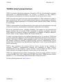
TOPEX brief presentation
TOPEX is a group of Romanian companies, founded in 1990, by 10 enthusiastic engineers
experienced in telecommunications. Its activity is directed to the research,
development and production of telecom equipment as well as service for them.
TOPEX becomes very quick the most important supplier of IT&C solutions for small to
large companies as well as for telecommunications operators and providers in Romania.
The company designs equipment for all existing mobile systems (GSM, CDMA), including
3G technology.
TOPEX is reperesented all over Romania by a wide network of local distributors through
which the promotion, administration and product maintenance are running.
Due to our innovation power, authentic flexibility, real respect for our parteners and
secure solutions that we provide TOPEX extended its business worldwide. Currently
TOPEX delivers its products through its distributors to: Republic of Moldova, Bulgaria,
Greece, Spain, France, Nigeria, Russia, UK, Turcia, Olanda, etc.
In order to achieve effective and flawless manufacturing for its products, TOPEX has
carefully organized its Research and Development Department along with its production
facility. This allows TOPEX to have maximum control of all the processes involved in
the complex operations related to high-technology electronic manufacturing. At the
present time, the Research and Development Department counts 30 specialists and the
trend is ascending.
TOPEX’s also considered the training and the service as part of the solutions it
provides. Therefore, comprehensive trainings are organized at Topex Factory,
complimentary for the company’s clients. Service is also provided via internet, as all
Topex solutions are designed especially to allow this, at the lowest cost.
TOPEX has implemented the quality management system according ISO9001 standard
certified by SRAC since 1997, respectively by IQNET since 2002. TOPEX become a sector
member of I.T.U. (International Telecommunication Union) since 2001.
For more details please visit www.topex.ro
OAM Manual
page 4 / 96
TOPEX SA
1
ISDN OAM v 1.32
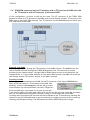
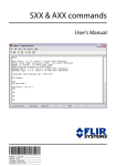
PRODUCT HARDWARE DESCRIPTION
TOPEX ISDN gateway achieves a direct link between the ISDN phone exchange in your
office and the wireless phone network. Consequently, it is easier to connect and the costs of
fixed-to–mobile calls will be cut down by as much as 60%. You will avoid telephone fees for the
interconnection between GSM network and the PSTN carrier. Also, calls coming from the cell
phones of your personnel out in the field will be cheaper as well.
Figure 1. TOPEX ISDN gateway interconnection
OAM Manual
page 5 / 96
TOPEX SA
ISDN OAM v 1.32
2 GENERAL DESCRIPTION OF OAM APPLICATION
2.1 Introduction
TOPEX ISDN gateway is a digital mobile phone interface that uses 2G/3G internal modules
for voice communications and SMS transmissions. It is connected to an ISDN PABX via NT and TE
ports, or to the public ISDN network. The TOPEX ISDN gateway may afterwards be accessed
from every local extension of the phone exchange. Also, each local subscriber connected to the
PABX can be reached from GSM mobile phones in the field at the most favorable mobile phone
tariff via the TOPEX ISDN gateway interface. Moreover, it performs call-back operation.
The TOPEX ISDN gateway may be configured efficiently and user-friendly by means of the
OAM program “ISDNoam”, which runs as a Windows application. The program is also used to
store on your PC the billing files, to save / reload configuration parameters, or to upload a new
firmware to the Topex box.
This document includes information on installation, configuration, and usage of the OAM
program.
Topex reserves the right to make technical changes that serve the safety of the device and
improve its operation.
2.2 Installing the program
This OAM program is intended for the configuration and administration of the TOPEX ISDN
gateway equipment via serial port. Also, the program allows you to send and receive SMS
messages from the computer that is connected to the equipment.
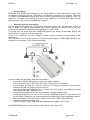
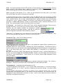
The serial connection is made by means
of the special serial cable (which
supplied in the TOPEX ISDN2GSM
package).
This cable features a RJ-11 connector
for connection to the TOPEX ISDN 2 GSM
unit and a standard DB-9 connector for
the COM port of the desktop PC or
notebook computer you use to configure
and administrate the equipment.
The installation CD or diskette supplied with the equipment includes the OAM (Operation,
Administration, and Maintenance) software and the user manual in electronic format.
OAM Manual
page 6 / 96
TOPEX SA
ISDN OAM v 1.32
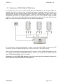
The ISDNoam.exe program is a self-contained Win 32 executable and may run on any
desktop PC or laptop that does fulfill the following minimal requirements:
- Operating system: Windows 98 or later versions
- Minimum processor 486
- RECOMMENDED MINIMUM 500 MB FREE SPACE ON HDD
- Minimum 256 MB of RAM
- One serial R-S232 port free (available for the connection)
- Graphics resolution 1024 by 768 pixels - colors High Color (16bit) or True Color (32bit)
The OAM program does not require a special installation; you simply copy it to a location
of your HDD. Just insert the diskette or CD into the respective disk drive unit and copy the
structure of folders and files to your hard disk drive.
Then run the file ISDNoam.EXE from the directory on your hard disk.
This is the recommended procedure.
But even if you have copied only the executable application, upon first run, it will create
the required auxiliary files and sub-folders for the configuration, billing and log files: CONFIG,
OUT, SAVED.
In these directories the OAM program will store all configuration files, files with
information about billing, SMS sent and received, settings, saved configurations, and “trace”
debug information.
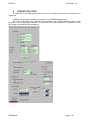
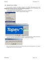
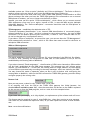
The Topex ISDNoam.exe application
can now be executed, either from
this directory directly or via a
shortcut symbolic link that can be
created manually e.g. on the desktop
as shown in this example:
OAM Manual
page 7 / 96
TOPEX SA
3
ISDN OAM v 1.32
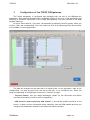
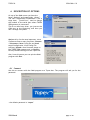
Configuration of the TOPEX ISDN gateway
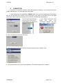
The Topex equipment is configured and managed with the aid of the ISDNoam.exe
application. After starting the application, by double-clicking on the icon of the application and
achieving a successful connection to the TOPEX ISDN gateway, the main window of the OAM
program opens up.
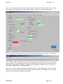
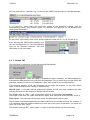
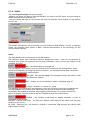
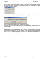
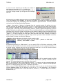
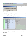
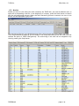
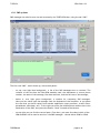
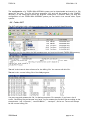
On top it shows tabs for “file cards” corresponding to different function groups. When you
click on a tab, the corresponding “file card” opens up, such as the Routing screen shown below
in the middle of a saving operation:
The tabs are arranged on the menu bar in a logical order, for an ergonomic, easy to use
configuration. You may go easily form one tab to the next, or to a different one. These file
cards corresponding to configuration screens are, from left to right:
- Direction Names, lets you assign meaningful names for the directions and define
overflow (forwarding of calls in case of congestion);
- GSM channel 0 and respectively GSM channel 1, sets up the mobile interfaces of the
device. It shows current information about subscriber card and GSM module and lets you
configure all parameters related to the respective mobile network;
OAM Manual
page 8 / 96
TOPEX SA
ISDN OAM v 1.32
- ISDN-cfg, configuration of the ISDN interfaces (NT and TE ports);
- Routing, where you define the rules for routing of the outgoing calls;
- CLIP list, a list of callback or forwarding operation for the incoming calls, including all
settings for different modes of call-back operations;
- DynCLIP, complementary dynamic list with automatic CLIP for call forwarding and callback service;
- Replace Identity, may replace for certain prefixes the first digits of the ID with
compatible values;
- Trace, advanced log / debug files recording the data transfers over the NT and TE
ports of the ISDN interface;
-Monitor, Live Monitoring of the calls made through the TOPEX ISDN gateway, for
checking and debugging;
- CDR, Call detail records, detailed listing of the durations of calls performed, for billing
purposes;
- SMS, for sending and receiving SMS messages and archiving the received messages;
- Terminal, direct connection to the GSM modules for sending AT commands and
following the response to these commands.
Warning: in the following pages you will see concrete examples of settings (telephone numbers,
mobile carriers, codes, and so on) than have worked for Romania.
Please remember that the direction names, operator names, phone numbers, the caller
identities, local extensions, IMSI codes and other values used in this manual are for example
purposes only;
OAM Manual
page 9 / 96
TOPEX SA
4
ISDN OAM v 1.32
CONNECTION
To achieve a connection between the OAM program running on your computer and the
TOPEX ISDN gateway, you must perform these steps:
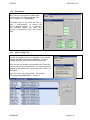
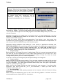
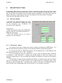
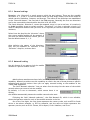
1. After calling up the application ISDNoam.exe, first go to the Application Parameters
tab and set correctly the number of the serial port to be used for the data link to the OAM
application (same with the physically port on which is installed the equipment):
This is a drop down list box,
you just select from it the
right number for "Serial port"
If you select incorrectly the
serial
port,
upon
first
connection attempt you will
get
this
error
message:
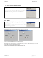
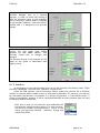
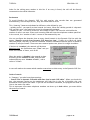
2. then click Save to store this value into
3. The connection to the Topex device is done by means of the "Options" tab:
4. The program asks you for the access password. The default password is “topex”:
OAM Manual
page 10 / 96
TOPEX SA
ISDN OAM v 1.32
- of course, if you type the password incorrectly, you will get an error message:
Try again, more carefully!
- if the port is correct, but the OAM application cannot find a connected TOPEX ISDN gateway
device, it will issue this error message:
This can happen in several cases: missing or defective serial cable, no equipment is detected;
the TOPEX ISDN gateway is not powered up, etc.
OAM Manual
page 11 / 96
TOPEX SA
ISDN OAM v 1.32
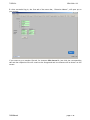
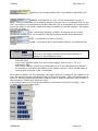
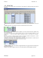
5. after successful log-in, the first tab of the menu bar, “Direction Names”, will open up on
your screen:
If you want to go to another file tab, for instance GSM channel 0, just click the corresponding
tab and the respective file will come to the foreground and its contents will be shown on the
screen:
OAM Manual
page 12 / 96
TOPEX SA
ISDN OAM v 1.32
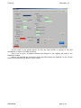
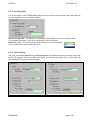
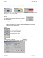
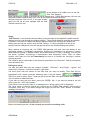
As you notice in the picture above, at first the field STATUS is colored in red, and
information in most or all fields is missing.
This is not an error, it happens because the program is just reading the state of the
respective module.
After a few seconds the information from the GSM module are gathered, so the current
values and settings will be shown on your screen:
OAM Manual
page 13 / 96
TOPEX SA
ISDN OAM v 1.32
OAM Manual
page 14 / 96
TOPEX SA
5
ISDN OAM v 1.32
CONNECTION STATE
To summarize, the OAM program can be in one of these three states of connection to a
Topex box
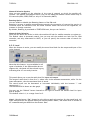
- Online, the program is actually connected to the TOPEX ISDN gateway.
The state of the serial port, indicated at the bottom, can be either Closed - meaning the
program is not exchanging information or data with the Topex equipment or Opened - when
the program interrogates the equipment:
OAM Manual
page 15 / 96
TOPEX SA
ISDN OAM v 1.32
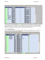
- Offline, when no equipment is connected, but you may use the OAM program to see a saved
configuration, to perform Save or Load, to upload a new firmware image, or to see the Call
Detail records or the SMS messages sent and received by means of the Topex box:
Listing of SMS sent or received via ISDN gateway, while the equipment is not connected
(Offline):
OAM Manual
page 16 / 96
TOPEX SA
ISDN OAM v 1.32
6 DESCRIPTION OF OPTIONS
On top of the OAM screen you have the
items „Options” and respectively „About”.
The tab <<Application Parameters>> has a
singe item, „Serial Port”, used to change
the number of the serial port where TOPEX
ISDN gateway is connected.
This is not used very often, you just set the
COM port at the beginning, and then you
don’t change it anymore.
Options is by far the most important, since
it allows access to many functions: Connect
/ Disconnect, Save Config file and Load
saved Configuration, View Config File
(offline), Upload a new firmware image to
the TOPEX ISDN gateway unit, or Restore
Factory Default settings for the Topex box.
Also, from this menu you can quit the OAM
program with Exit.
6.1 Connect
Use this to connect with the OAM program to a Topex box. The program will ask you for the
password:
- the default password is “topex”
OAM Manual
page 17 / 96
TOPEX SA
ISDN OAM v 1.32
6.2 Disconnect
When you are connected to TOPEX ISDN
gateway, the only item available in the
menu “Options” is … Disconnect.:
This means that, if you want the Save or
Load a configuration, to restore the
factory default settings, or to upload a
new firmware image, you must first
perform a Disconnect from the current
state.
6.3 View Config File
You can use this option, in a disconnected state (as you
can see, the option Connect is available, which means
that you are NOT connected to MobiLink), to view a
configuration file that you have saved previously.
Since you are not actually connected to the Topex box,
you can only see the configuration, you cannot perform
changes of the parameters, hence the name “View” for
this option.
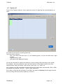
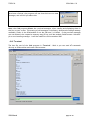
When you click “View Config File”, the window
<<Viewing CONFIGURATIONS>> shows up:
OAM Manual
page 18 / 96
TOPEX SA
ISDN OAM v 1.32
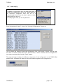
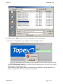
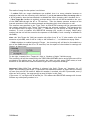
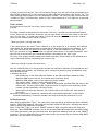
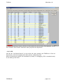
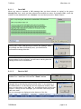
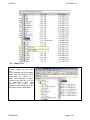
The “.cfg” files are listed with their names, length in bytes, and creation date (date + time).
Select the one you want to load, then click the button “Load” to view this configuration:
First of all, notice that not all the tabs for card files are present in the menu, only the first
ones. See below for comparation the tabs menu in a Connected state:
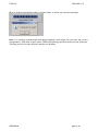
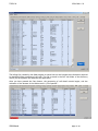
Trace, Monitor, SMS, Terminal are not shown because they cannot perform in a disconnected
(Off-line) state. This disconnected state is also indicated by the status box at the bottom left of
the screen, which shows “Offline” on a light blue background, instead of the “Port open” or
“Port closed” indication in a connected state.
Second, the “Save” button is missing from all the screens of the OAM program. This is because
you can only view a configuration that has been saved previously, you cannot perform changes,
and you are not allowed to modify the settings.
OAM Manual
page 19 / 96
TOPEX SA
ISDN OAM v 1.32
6.4 Saving and loading system configurations
There are two Menu options for saving and respectively loading
configurations from / to the TOPEX ISDN gateway. Those
functions are valid only in the situation when the OAM program
is not in a state of connection with TOPEX ISDN Gateway. As
you can see in the image to the right, the option Connect is
available while Disconnect is disabled, this means you are NOT
connected to the TOPEX ISDN gateway.
To save a configuration click the “Save Current Config To File” from the icon and the following
dialog window shows up:
- first, the program asks you for the access password:
- if you typed the correct password, a window shows up asking you a NAME for the saved
configuration, you should enter a meaningful name (relevant for the respective set of
parameters):
- the saving of the configuration begins, you will see a progress indicator for each item (GSM
settings, Routing table, static CLIP and Dynamic LCIP, Replace table):
- after successful saving of all components, a confirmation message will be displays, telling you
that the “Configuration was saved!!”:
OAM Manual
page 20 / 96
TOPEX SA
ISDN OAM v 1.32
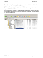
- The saved configuration is located in the “SAVED” sub-directory of the folder were you
have placed the OAM program:
In this subfolder are located all the saved configurations (sets of parameters for TOPEX
ISDN gateway ISDN). They are files with the "cfg" extension that is added by the program to the
name you have filled in.
The configuration contains the settings for directions assignment, PIN codes, level and
network settings, targets, routing table, static and dynamic CLIP-GSM table and prefix
replacement information..
OAM Manual
page 21 / 96
TOPEX SA
ISDN OAM v 1.32
6.5 Load config
To restore a configuration that you have saved, that is
to load the configuration file to the TOPEX ISDN box,
the respective equipment must also be in a
“disconnected” state. From the Menu Options, select
“Load Config File to Unit”:
The OAM program asks you for the password.
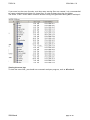
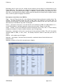
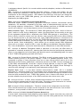
Enter the password “topex”, then a list “Viewing Configurations” shows up:
The list shows the names of the saved configuration files, their length in bytes, and the date
and time of creation (date-month-year hour-minutes). Select from the list the configuration
you want to restore then click the “Load” button.
The program begins loading the different components of the configuration to the TOPEX ISDN
gateway unit. It displays the name of each item loaded, together with a progress bar:
OAM Manual
page 22 / 96
TOPEX SA
ISDN OAM v 1.32
When it finishes (the Replace table is the last item), it shows you a success message:
Note: It is strongly recommended that before loading a new image file, you save the current
configuration, then load it again when TOPEX ISDN gateway operates with the new firmware.
This way you are sure that all your settings will be kept.
OAM Manual
page 23 / 96
TOPEX SA
ISDN OAM v 1.32
6.6 View CDR/SMS
Select this item from the Options menu to view the
CDR records or stored SMS messages form an on-line
(disconnected ) state:
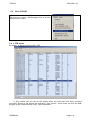
6.6.1 CDR option
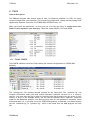
By default, it opens to the first tab, CDR:
In this window you can see all the details about the calls that have been recorded
previously. Notice at the bottom the indication “Port Closed”, which shows you that the OAM
program is Not communicating with a Topex equipment.
OAM Manual
page 24 / 96
TOPEX SA
ISDN OAM v 1.32
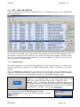
6.6.2 SMS – SEND AND RECEIVED
Click the tab SMS to see the text messages sent or received by means of the TOPEX ISDN
gateway equipment:
You can use the scrollbar to the right to move up and down in the list of SMS messages, or you
may define a certain period to filter out or to delete the saved text messages. Since the Topex
box is not connected, you cannot transmit or receive messages, you can only see the ones
already stored by the OAM program.
6.7 Upload image
This facility allows you to up-load to the Topex box a new software image, a version of the
firmware application running on the TOPEX ISDN gateway system (to perform a firmware
update).
Using the ISDNoam.exe application, a new version of the firmware can be transferred to the
Topex box via the serial data link. Before you do this, first check the version of the firmware
running on your device, to avoid uploading an older or incompatible software image:
The current version of the firmware used in TOPEX ISDN gateway is
displayed, in a connected state, at the bottom right corner of the
OAM screen, below the Topex logo, such as “isdnalG4.1_128”:
Warning! This is a two-step operation, because to find out the
version, you must be in a state of connection between OAM and box,
the bottom left indicator should show either the red indication
“Port opened” or the blue “Port closed”
but afterwards, to actually load the image file, the program must
be disconnected form the TOPEX ISDN gateway. Select
Options>Disconnect, the serial port indicator will show “Offline”
:
OAM Manual
page 25 / 96
TOPEX SA
-
ISDN OAM v 1.32
then from the same Options menu, select “Upload Image
to Unit”:
The program will display the normal Windows dialog for opening
files, where default type is “image file”.
Go to the folder that stores the firmware images, such as “Updates” on the C: drive in this
example
Open this folder, and from it select the “.hex” file that is to be transferred to the TOPEX ISDN
gateway, such as isdngs_all_41_128_c.hex in this example:
OAM Manual
page 26 / 96
TOPEX SA
ISDN OAM v 1.32
By clicking on the “Open“ button, the first OAM asks you for the password.
- if you type a wrong password, you will get an error message as shown:
if you have entered the correct password, the transfer of the firmware image file to the
TOPEX ISDN gateway begins.
The new software image is divided in several successive packets which are sent to the TOPEX
ISDN gateway via serial connection.
The reception of each packet must be confirmed by the equipment. As the software is uploaded, a progress bar shows the transfer of each packet.
-
OAM Manual
page 27 / 96
TOPEX SA
ISDN OAM v 1.32
The message displayed is “Loading new image
xxx/yyy”, where xxx is the number of the current
package and yyy is the total number of packets of
the file, such as 270 in the example to the right:
When it is finished, you see “270/270” , meaning
all packets have been transferred, and an
additional
message for confirmation of the
successful up-loading of the new firmware:
- to ensure proper operation, the unit with the new firmware should be restarted, by
performing a “Reset“ - pull off he power supply jack then plug in back after 10 seconds.
- now you can connect again with the OMA program to the TOPEX ISDN gateway unit, which runs
the new firmware.
Attention: The files to be loaded have the extension "hex". To avoid malfunctions, only files
approved by TOPEX should be loaded into the device. The image files are available form the
website of the TOPEX company.
In case of a power failure during reprogramming of the device or any other event that
invalidates the program storage of the equipment, the unit could become non-operational. In
this case you should call SERVICE to perform software repairs.
Important notices related to the loading of a new version of application software into
TOPEX ISDN GATEWAY. Be careful when you load an update file. If you select a wrong kind of
file, or if for different reasons firmware upgrading fails, the TOPEX ISDN GATEWAY will no
longer operate correctly. In some cases you will need to contact the manufacturer for repairs.
To avoid this, follow carefully the rules indicated here:
• Always backup!
Before loading of the image file (menu "Loading Image File") it is strongly recommended that
you save the current configuration of your TOPEX ISDN GATEWAY unit. Click the icon "Save
current configuration". Then, after you performed the loading of image file, reload the saved
configuration by clicking the icon "Load configuration".
If you don’t do this your settings may be lost upon loading a new image file.
• Correct version
Make sure that you get the correct version. First, you want to make sure that the file you load
is newer than your current firmware version. Second, check that it is the variant that is right
for your equipment. The TOPEX ISDN GATEWAY devices may have two types of processors:
codes are _64 and respectively _128.
Make sure that the image file that you load is suited for your processor. If you have older
equipment, that doesn’t show the _64 or _128 termination, it means you must look for
firmware versions type _64.
• No interruption
Never turn off the TOPEX ISDN gateway equipment or the computer while the firmware is being
overwritten.
Make sure that the adapter and your PC don’t turn off during update. It is better to use an
uninterruptible power supply (UPS) for this purpose.
OAM Manual
page 28 / 96
TOPEX SA
ISDN OAM v 1.32
• Always backup!
Remember that updating the firmware on the Topex ISDN box could cause some or all of the
configuration settings to be lost, depending on the degree of change in the firmware. Therefore
it is highly recommended that you save your current configuration before updating, then you
restore it. To backup your settings, perform a Save, update the firmware, and then Load the
saved settings, after you have updated the firmware.
• Resuming after an interruption:
If the loading of the image file is interrupted (the mains power fails, the operating system on
the PC stops, the cable is disconnected, etc) before reaching its normal ending, the new
software may not be fully installed so the equipment it won’t work.
To correct this, you should first reset TOPEX ISDN gateway (by taking off the supply jack for ten
seconds) and try again to load the image file.
If this is not successful, you must change a jumper setting to perform forced loading of the
application.
JP 5 is located near the top left corner of the printed circuit board of TOPEX ISDN GATEWAY, see
indication of its position in the following drawing:
You must follow the procedure steps described below:
- power down TOPEX ISDN gateway (unplug the supply adapter)
- open the plastic case of the device and look at the printed circuit board
- locate jumper JP5 (top left, near the connector for antenna, as shown in the following
drawing) and place a jumper on these two pins
- start up the OAM application with the “l” option. For this you go to the MS-DOS command
line prompt and type: “ISDNoam.exe –l”
- from the OAM program select the menu Options “Upload Image to Unit”
- choose the image file you want to load into the ISDN2GSM equipment. Note that in this
forced mode of operation the authentication by password will not be requested anymore
- after the loading of the image file is ended, power down TOPEX ISDN GATEWAY
- remove the jumper from pins JP5
- close the case of TOPEX ISDN GATEWAY equipment and tighten the screws.
Now TOPEX ISDN gateway can be used normally with the new image file.
OAM Manual
page 29 / 96
TOPEX SA
ISDN OAM v 1.32
Explanation:
In normal operation, the bootloader is started first, upon power-up of TOPEX ISDN gateway.
When the loading of a new image file has been interrupted before normal termination, the
program loaded in memory may be corrupted, so it won’t work correctly. To remediate this,
you must place a jumper on pins JP5 to force the bootloader to start. Then it can load the
application and download a new (correct) image file for TOPEX ISDN gateway.
To avoid going to the command
prompt or using the Run option in the
Windows Start menu, you could create
a shortcut for launching the OAM
application with the “-l” parameter.
If you click the “Loader” shortcut
instead of the ISDNoam application
itself, it will automatically launch the
program with the option “-l”, thus
forcing the loading. This shortcut may
have associated a different icon, so
you know which is the normal program
and which for emergency repair:
When you finish repairing the firmware, remember to take the jumper off pins JP5 before
resuming normal operation of the TOPEX ISDN gateway!
OAM Manual
page 30 / 96
TOPEX SA
ISDN OAM v 1.32
6.8 Upload Factory Setting
You may need to restore the default settings on the TOPEX ISDN gateway (the initial
configurations from the factory). Use this command to delete all current parameters and
reinstate the parameters that were established by the manufacturer.
For this, you perform the following steps:
- start the OAM program, the OAM is not connected to the Topex box;
- from the Menu “Options”, select “Upload factory Settings”:
-
you must Log-in, the program asks you for the password:
-
if you have typed the correct password (topex), the program quickly uploads the default
settings to the TOPEX ISDN gateway and shows a confirmation message:
-
now, you may connect to the box for performing the required configurations, or to load a
configuration that was saved previously.
OAM Manual
page 31 / 96
TOPEX SA
ISDN OAM v 1.32
6.9 Exit - Exit from the OAM program
In a connected state, you should first Disconnect the OAM
program from the box, then click Exit to quit the OAM
program.
If you try to select the option Exit directly, you will see
that it does not work, you must first click Disconnect …
6.10. About
To the right of the “Options” item, you have “About”. It
is available in any state: connected or disconnected, port
open or closed.
Select “about” to see the current version of the OAM
software running on your PC.
About displays the version of OAM software, such as 1.13 or 1.32:
Click to the button Hide to close the About window.
Remember that some features are available only in newer OAM releases, be sure that
your OAM program is the latest version.
The current User Manual refers to OAM version 1.32.
OAM Manual
page 32 / 96
TOPEX SA
7
ISDN OAM v 1.32
CONNECTION EXAMPLES
Before studying how to make use of the OAM tabs to set up routing rules, it is useful to review
the possible modes of using TOPEX ISDN gateway together with a PABX private exchange.
In the following pages there are shown a few examples of interconnecting the TOPEX ISDN
gateway equipment. The ports of the Topex box are figured as blue squares on the light blue
background – two radio ports (the GSM modules) and two wired (ISDN) ports:
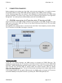
7.1 ISDN2GSM connected on its NT interface with a TE interface of PABX.
The NT connector of the ISDN-2-GSM is linked to a TE junction of the PABX, another TE of the
PABX goes to the public ISND, and TE port of the ISDN-2-GSM may linked to the TE of the PABX
only for synchronization.
The SYNCRO clock (dotted lines) is received from the Public fixed telephony network (ISDN).
The TE interface of the PABX is acting as a junction.
Outgoing from PABX
If the call is to mobile networks, the PABX routes it to through the TOPEX ISDN unit. The
numbering is sent through the TE junction of the PBX to the NT connector of the TOPEX ISDN
GATEWAY. TOPEX ISDN gateway performs further routing, it uses one or two directions for the
calls received from the PBX: DIR0 for module GSM0, one mobile network, DIR1 for module
GSM1, the other mobile operator. The call will be routed according to the number dialed to the
respective mobile operator
If the number dialed is for the public ISDN network, the PABX routes it through the TE junction
connected directly to the public network, by-passing the TOPEX ISDN gateway unit.
OAM Manual
page 33 / 96
TOPEX SA
ISDN OAM v 1.32
Incoming from GSM to PABX
From the 2G/3G network an incoming call will be forwarded to the NT interface. The decision
is taken depending upon the CLIP GSM table or the Dynamic CLIP list. If the incoming phone
number is not found in the table, decision is taken depending on routes from the GSM module.
The options involved are DISA, OPERATOR and the Target settings (from the CLIP table or from
the GSM settings).
The destination of the call will be a specific local extension of the PABX or the operator of the
exchange.
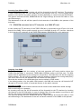
7.2 ISDN2GSM connected on its TE interface to a PABX NT local.
In this variant the TE connector of the TOPEX ISDN box is connected to the NT port of a local
board of the PABX. Calls to public network go out of the PABX through a TE junction. Note that
in this case the NT connector of the TOPEX ISDN gateway ISDN2GSM unit is not used at all.
Outgoing from PABX
The local subscriber dials the number of the local extension (NT local) position where the
TOPEX ISDN GATEWAY is connected. TOPEX ISDN GATEWAY answers with dial tone. The DISA
option must be established in the settings for TE interface. The subscriber will dial the outgoing
mobile number. The call will be routed on a 2G/3G module by applying the routing table policy
(the call is sent out into the adequate 2G/3G network for least costs).
Note that the number of the GSM subscriber must be dialed in DTMF mode!
If the dialed number is for the public ISDN network, the PABX will route the call instead of NT
through its TE junction which is connected directly to the public network.
Incoming to PABX
The calls coming from the mobile networks can be routed to their destination either through
DISA or with help of an operator.
An incoming call from the 2G/3G networks will be forwarded to the TE interface by checking
the identity in the CLIP-GSM table. In case of missing Caller ID or the number is not found in the
records, the routing is performed by checking the GSM settings.
The involved options are DISA, OPERATOR and the Target settings (from the CLIP table or from
the GSM settings). The destination of the call will be an extension of the PABX or the operator.
OAM Manual
page 34 / 96
TOPEX SA
ISDN OAM v 1.32
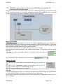
7.3 ISDN2GSM connected on its NT interface with PABX and with the TE
interface with the public ISDN.
Only one TE junction of the PABX is used in this case. TOPEX ISDN gateway is connected through
its TE interface directly to the public telephony network. The ISDN2GSM unit is inserted
transparently between the public telephony network and the ISDN PBX.
Outgoing from PABX
The PABX exchange will forward the calls to the TOPEX ISDN2GSM system. The numbering is
sent directly from the TE junction into the NT connector of TOPEX ISDN GATEWAY. In this case,
calls coming in through NT connector of TOPEX ISDN gateway can be routed through one of
three directions: GSM0, GSM1 and TE (to public network).
The routing is performed by the TOPEX ISDN gateway, not by the PBX.
The call will be routed according to the number dialed either through GSM0, GSM1 or the TE
interface.
The user can place the module GSM 0 on direction 0 and the GSM1 on
direction 1.
The TE interface will be placed on the third direction
Incoming to PABX
The calls from the public ISDN are transferred transparently towards the
PABX.
For this, in the configuration window for Incoming Calls of the TE
interface you must select the “PassThrough” option.
The "TE" from the PABX will act as a junction.
The calls coming in from the 2G/3G networks are analyzed by checking the identity in the CLIPGSM table.
If the ID is missing or the caller is not found in the CLIP-GSM records, routing will be performed
by TOPEX ISDN GATEWAY according to the settings of the GSM module.
The incoming calls from the mobile network can be routed either through DISA or with help of a
human operator.
OAM Manual
page 35 / 96
TOPEX SA
ISDN OAM v 1.32
7.4 ISDN2GSM connected on its NT interface with a TE junction of PABX and with
its TE interface with NT interface of the same PABX.
In this configuration, all ports of the box are used. The NT connector of the TOPEX ISDN
gateway is linked to a TE junction of the PABX (one junction board). Another TE junction of the
PABX goes to the public ISDN network. The TE connector of the ISDN2GSM goes to the NT port
of a local board of the PABX.
Outgoing from PABX
The outgoing calls exit through the TE connector of the PABX junction. The PABX directs the
calls to mobile networks through the TOPEX ISDN gateway unit. The calls will be routed
according to the number dialed through GSM0 or GSM1 placed on one of two directions (for
example 0 and 1). If the number dialed is for the public ISDN network, the PABX will route the
call through another TE junction, directly to the public network.
Incoming to PABX
Calls from mobile networks get into PABX via the TE connector of the Topex ISDN2GSM unit.
When a GSM call comes in, if the setting in the GSM “Call
handling” window is Use target No, the call will go to the
local extension you have specified in the field “Target No”.
From the PABX this is the same as if it were a local call!
If the setting is DISA, the caller gets a DISA tone and he can dial any local subscriber he wishes.
Also, he can make calls to the public network, acting as a local subscriber of the PBX.
Incoming calls from the 2G/3G networks will be forwarded to the TE interface by checking the
identity in the CLIP-GSM table and in case of missing ID or number not found in the records, by
checking the GSM port settings. The GSM options are DISA, OPERATOR and the Target.
OAM Manual
page 36 / 96
TOPEX SA
ISDN OAM v 1.32
7.5 Using several TOPEX ISDN GATEWAY units
It is possible that you need to connect more than one ISDN2GSM unit to the same PABX. For
example, you want to use more than two mobile operators for optimal routing. For instance, in
Romania there are four different mobile network providers. Alternately, you may want to have
several 2G/3G modules for the same operator, if there is an intense GSM traffic or if you have
established that when one 2G/3G module is busy, the call to be routed through another
module. In this case several ISDN-2-GSM units (two, three or more) will be used with the same
PABX. You must ensure synchronization of all the TOPEX ISDN gateways.
For this purpose, clock synchronization is taken from the Public ISDN and goes to the TE
connector of the first TOPEX ISDN gateway, shown to the left in the above picture.
Then the clock signal goes out through the SYNC connector of that TOPEX ISDN gateway to the
TE connector of the second TOPEX ISDN gateway, and so on in a daisy chain. You can have as
many TOPEX ISDN GATEWAY units as you need.
Remember, the last TOPEX ISDN gateway in the chain must have the termination resistors for
the TE interface activated (hardware configuration).
OAM Manual
page 37 / 96
TOPEX SA
8
ISDN OAM v 1.32
DESCRIPTION OF TABS
On the Menu, below Options, a menu bar is shown, containing several tabs for file cards. Their
number depends of the connection state, which is when the program is connected to a Topex
box, all the tabs are available, while in offline mode of operations, only some of the tabs are
shown. Clicking on a tab, brings to the front the respective file card (screen of settings).
These tabs are described from left to right:
8.1 Direction Names
If you select the "Direction Names" tab in the
"menu bar, the window for editing the names
of the directions and configuring call
diversions will be displayed:
Here you can:
- define the direction names (The TOPEX ISDN
gateway unit box can handle a maximum of
three real directions);
- fill-in the overflow rules to be used in
operation for call diversion.
8.1.1 ”Directions” option
The routing of the calls is based upon rules for dialing and defining of DIRECTIONS – in a
PBX, the directions are groups of trunks or lines that have similar routing characteristics.
Two of the directions of TOPEX ISDN gateway can be assigned one to each GSM port and
the third to PSTN (on the "TE" or “NT” interface).
You may change the name for directions 0,1 and 2 from the default names "Direction
0","Direction 1" and "Direction 2". Usually, you should assign to them the names of the
respective mobile carriers, such as Orange and Vodafone for Romania, as shown in the following
example.
The "Direction 3" name can't be changed from Default. It is shown in gray color to indicate
that it is not editable. This fourth direction is not a real direction for routing the calls, it may
be used to reject (forbid) calls. If you select this “dummy” direction in the Routing Table for
some prefixes, the corresponding calls will be forced to a “non-existent” direction.
OAM Manual
page 38 / 96
TOPEX SA
ISDN OAM v 1.32
Usually, the two mobile modules are
includes, assigned each to a network
operator, in order to ensure the routing of
calls for minimum costs. In this example,
the first direction, module GSM 0 is assigned
to the provider Vodafone, while the second,
module GSM 1, is assigned to the provider
Orange.
But if a group of subscribers have higher
priority, you may assign both mobile
modules for the same carrier, with
direction names such as Orange1 and
Orange2.
The direction Orange 1 will reserved for the
usage of the group of subscribers with
higher priority.
8.1.2 Overflow
At the bottom of the previous image you can see the overflow (call divert) panel. There
are three “Direction” rows with two “Overflow” columns each.
Inside the GSM network, the call diversion feature makes the network call a different
number in case the dialed number is busy or otherwise unreachable. For instance, you may set
up a diversion from operator 1 to operator 2, to always ring operator 1. If the mobile carrier 1 s
is busy or unavailable, operator 2 will be called automatically and the customer does not need
to manually make a second call.
Each line is used for one direction and establishes the
first and the second overflow option. For each overflow,
the direction numbers can be Direction 0, 1 and 2, or the
names you previously defined – Vodafone, Orange and
respectively PSTN.
OAM Manual
page 39 / 96
TOPEX SA
ISDN OAM v 1.32
Should you want to specify that a direction does not have an overflow, simply set that
field to the same name as the direction name.
For example at the direction "1" - named "Vodafone", if you specify "Overflow1" =
"Vodafone" then no overflow will be set. This is the default configuration.
If you specify "ORANGE" then when the direction "CONNEX" is unavailable of busy, the
direction "ORANGE" will be used to route the call. You can also select a second overflow
direction (Overflow2) to be used for call diversion in case the first overflow direction also
becomes unavailable of busy.
You may also use the Overflow feature to implement a higher priority for a group of
subscribers. In the example above, only the high priority clients are assigned to the direction
Orange1, and if this direction is unavailable (the respective mobile module is busy), it will
overflow over the direction Orange2, which is used by all the local subscribers.
8.2 GSM module configuration –GSM channel x
To configure a GSM module (0 or 1) click on its tab at the top of the screen and the “GSM
Settings” window shows up, allowing you to specify the operating parameters for the respective
GSM module:
Depending of the selected 2G/3G module the title of the open tag will be "GSM channel 0"
for the first 2G/3G module and respectively "GSM channel 1" for the second GSM module.
Also, a few features (Network selection, Level) are available only with certain types of
mobile modules.
OAM Manual
page 40 / 96
TOPEX SA
ISDN OAM v 1.32
8.2.1 General settings
Direction - the “direction” or trunk group to which the port belongs. There are four possible
directions: 0, 1, 2 and 3. To the first three values you may assign names, such as the names of
mobile carriers (Vodafone, Cosmote, and Orange). The names of the directions are established
in the “Direction Names”, the first tab of the OAM program. Generally the first two directions
are for the two mobile networks while the third is for the PSTN
The fourth direction, Direction 3, cannot be renamed, since it is not a real one, it is used only
to forbid (prohibit) access to certain prefixes. “Direction3” is in fact a rejection criteria, it is
used for telephone numbers that you want to be rejected (no calls are allowed towards these
numbers).
Select from the drop list the “direction” where
the current mobile module will be assigned. If
you have not defined direction names, you will
see the default names: 0, 1, 2.
After defining the names of the directions,
they will be available for selection in the
“Direction” drop list, as shown here:
8.2.2 Network locking
Use this feature if you want to lock the mobile
module to a specific mobile carrier.
Mobile phone manufactures have built into GSM phones the network lock or subsidy lock
capability. Network providers can this capability to restrict the use of these phones to specific
countries and network carriers. Here you can apply network locking to the modules of the
TOPEX ISDN equipment.
The field “Network selection” lets you select from the drop list the name of the mobile
network where you want to lock the module.
By default, it is set on Automatic, which means there is no
locking,
the module automatically detects the mobile network to be used.
Following the field “Network selection”, the field Network ID, which is not editable,
shows the Operator codes for each of the mobile networks in the list.
Out of the five digits, the first three represents the country code, such as 655 for South
Africa in the above example, or 505 for Australia, and the next two digits represents the
operator (carrier) such as 01 for Telstra, 02 for Optus, 03 for Vodafone, and so on/
OAM Manual
page 41 / 96
TOPEX SA
ISDN OAM v 1.32
You may edit the file “operator.cfg”, located in the CONFIG sub-directory of the OAM program:
It is a text file, where there are stored the names of the operators together with the
corresponding country and network codes. For example, the operator file for Romania may
contain this information:
As you notice, the country code is 226, and the operator codes are 01, 10, 03, 05 and so on.
After starting the TOPEX ISDN gateway with
the new configuration file, the corresponding
drop list for “Network selection” will look
like shown in the next image:
8.2.3 SIM and SMS
The next block of settings is for the SIM card and GSM module:
Delete incoming SMS - when this option is enabled (the box is checked), the SMS messages are
automatically deleted after being received and displayed. This is useful when you get many SMS
messages, because if they are not deleted in time, they would fill the storage memory.
If the working memory is full, new messages can no longer be received, so you must delete
them, either manually after reading or automatically.
SIM PIN Code – it the SIM card has enabled the request for PIN, you must complete this field
with the PIN code for the respective SIM and 2G/3G module.
The default value is “1234” - this is used when checking for PIN code is not enabled.
The length of the field "Pin Code" must be four digits, with individual values between '0' and '9'.
Timer Reset – the time interval following which the GSM module will be reset.
This is useful in situations imposed by the particularities of the mobile network. For instance, if
it is requested that the mobile modules are reset every two hours of operation, you enter the
value 120 in the field Timer.
The default setting is OFF, which means no reset of the GSM module will be performed!
OAM Manual
page 42 / 96
TOPEX SA
ISDN OAM v 1.32
8.2.4 Incoming Calls
This section tells to the TOPEX ISDN gateway how to process the incoming calls (calls that get
into the equipment via the mobile module).
Allow Incoming Calls – by default it is checked, so the module can receive incoming calls.
If you disable this option, then all incoming calls will be rejected!
Destination port – you must specify which ISDN port is the destination
for the mobile calls; select either NT or TE.
8.2.5 Call handling
The next two options DISA Tone and Use target No are used for directing incoming calls from
the 2G/3G network. The option DISA and Target are mutually exclusive, only one of them can
be enabled by the user at a time moment.
TE settings – DISA Tone
OAM Manual
TE settings – Pass Through
page 43 / 96
TOPEX SA
ISDN OAM v 1.32
The mode of usage for the options is as follows:
- if neither DISA nor target checkboxes are enabled, that is a wrong situation because no
method to deal with the incoming call is defined. If you do not want to allow incoming calls on
a 2G/3G module, then the best method is to disable the "Allow incoming calls" checkbox for it.
- if Use Target No checkbox is enabled, as shown above, the call will be forwarded to the port
of the ISDN PABX through the NT or TE interface. Then the human operator answers at the
internal extension 1196 in the above example and decides which local extension to call.
The interface was specified in the "Type" field. An ISDN SETUP message will be generated with
the number specified in the "Target" field through the selected interface. The maximum size
for the target field is 4 digits. If you type "---" characters you can specify an empty target (no
number). In such a situation the ISDN-SETUP message will contain an empty called party
number and the call will be routed to the operator of the PABX (if such a setting is validated in
the PABX).
Note: the "Use Target No" field can contain only digits from "0" to "9" (the number of a local
extension of the PBX, such as 105 or 1196) or the characters "---" to indicate an empty value.
- if DISA checkbox is enabled instead of Target , the incoming call will also be forwarded to a
port of the PABX through the NT or TE interface, but the aspect of the window for settings will
change, as shown here:
To the right, instead of the “Target No” field, a “Number of digits” field shows up.
The incoming call will be answered by the TOPEX ISDN GATEWAY device and a DISA tone will be
provided to the calling party. On this tonality the caller can dial (using DTMF codes) a local
extension of the PBX or an external number to get out of the phone exchange.
Important! When DISA Tone checkbox is selected, the field “Target no.” becomes “Nr. Of
Digits” and instead of the target, it represents the maximum number of digits that are waited
to come from the 2G/3G network. When this number is reached, the call is forwarded, even if
digits are still coming. You may specify at most 20 digits in this field.
If you enter “0” no digits will be waited for. This means the ISDN-SETUP message will be sent
without any called party number in it.
OAM Manual
page 44 / 96
TOPEX SA
ISDN OAM v 1.32
8.2.6 Outgoing Calls
This panel holds settings for the outgoing calls:
Allow Outgoing Calls – if checked, the mobile port will be used for outgoing calls. If this box is
not enabled, the GSM module will NOT be used for outgoing calls;
CLIR - if this option is checked then identity of the call will not be sent (identity restricted). By
default, this checkbox is NOT enabled, so the identity will be sent out.
Note – the option CLIR enables or disables sending of ID for all the calls performed over the
respective mobile module. But the OAM program also has means to individually choose if you
want to send out or not the ID. For more info about this feature, see explanation in the
“Routing” tab, column “Identity”.
Call Progress Tones - if this option is checked then the user will hear in the headset the tones
indicating the phases of the call.
Call progress tones are audible tones sent from the PSTN or a PBX to calling parties to indicate
the status of phone calls. The technical characteristics intended usage for some wide use
progress tones are defined in the ITU-T recommendations E.180 and E.182.
When this feature is enabled, the user will hear a tone as soon as the numbering has been sent
to the GSM module, until the moment that ring back tone is received from the mobile network.
If you disable this feature, no tones will be sent, the user will hear only silence on the line and
he won’t know is the establishing of the call is going on or not.
No calls
When both incoming and outgoing calls are disabled, the GSM module is no longer in use for
calls.
In this case, the equipment will cut the power supply to the respective mobile module, which
will be in the state “power off”,
This state is indicated by a red RPS message in the
field Status.
OAM Manual
page 45 / 96
TOPEX SA
ISDN OAM v 1.32
8.2.7 Billing section
This panel is for billing purposes (charging of the calls). The ISDN gateway can send out
metering pulses for the purpose of accurately billing of the calls made through the equipment.
AOC – Abbreviation from “Advice of Charge”, a signaling protocol used to send charge (billing)
pulses to the PBX where TOPEX ISDN GATEWAY is connected.
AOC is the “charge” for the call, computed by the GSM terminal and expressed in terms of
Home Units. The charge pulses are sent at the beginning of the call and during the call,
according to two elements that you may program at the bottom of the window. For these, see
details below.
If the option "Audio Billing Pulse Warning" is enabled (the box is checked), then set the billing
pulses can also produce an audio (sound) confirmation at the calling party. This way, the caller
knows that the call is charged, and may get an idea about the costs of the call.
Pulses
The two items that you may set up here are the
number of initial pulses ("Number of pulses at
response") and the time delay between two
successive billing pulses ("Pulse generating period").
With the above settings, TOPEX ISDN gateway will generate two billing pulses upon answering,
and then the time interval for pulses (the metering period) will be of 15 seconds.
These values are configurable, since the actual price of a unit of cost changes from one mobile
network to another, as does the period after which billing pulses must be generated.
OAM Manual
page 46 / 96
TOPEX SA
ISDN OAM v 1.32
8.2.8 SIGNAL
The panel Signal Strength has several usages:
-displays info about the state of the GSM module, the level of the RF signal, the technology of
mobile network that is selected, etc.
- lets you choose the type of network and the order of selection, the activation of the roaming
service, etc.
The window periodically runs monitoring over the respective GSM module, in order to read the
status, the reception level (shown in dBm), and the identification of the technology for the
current mobile network.
Status
This field displays the current state of the GSM module.
The different states have associated specific background colors - blue for conversation or
incoming call, yellow for registered but not busy (available), red for errors (the module is not
available for calls).
RPS – the GSM module is powered off.
This can happen, for instance, when the module is NOT selected in the configuration. When
neither Incoming calls nor Outgoing calls are checked , the equipment shuts down the power
supply for the respective mobile module.
SIM_NRY - SIM card not ready. This message is shown also when no SIM
is present in the slot of the respective module.
commands.
INIT - module is in the initialization phase, initialized using AT
P_ON_M - module is in “power on” state.
This message is encountered in the beginning, when the Topex box just starts to operate and
the GSM modules are powered. Also, each time you perform changes over the operating
parameters, the module is resetted, after applying new settings, so it will go through the
phases P-ON and Search in order to become Registered with the mobile carrier.
SEARCH – the module is searching for mobile networks, it tries to
registered in the network
PIN_ERR - SIM PIN code error , the SIM card request a PIN code and the value that has been
entered is not correct!
OP_LOCK – Operator lock, the module is locked in a particular GSM network and cannot work
with another provider
OAM Manual
page 47 / 96
TOPEX SA
ISDN OAM v 1.32
Registered, the normal standby state – the module is registered with
the mobile network
SPEECH – the module is in a call, a voice conversation is going on.
ALOC - module is allocated for an outgoing call but the voice call AT commands were not yet
sent. The module is not available for another GSM call! This is encountered for instance when
not all the digits of the phone number have been received from the BRI interface, the module
still waits for digits.
DIAL – the module is dialing a number, an outgoing call ins routed
through this module and it is in the phase of dialing the phone number of the destination
ALERT - the module is in state of alerting
module.
INCOM – an incoming call from the mobile network is presented to the
Strength
-
The level of the signal received from the mobile network is
displayed in three different modes:
graphically, as an indicator bar, with one, two or more blue rectangles showing the level
of the RF signal
as a precise, absolute value, from one to three figures, such as -103 or -73. It is
expressed in dBm.
as a relative value on a scale from 0 (minimum) up to 31 (the maximum). For instance,
the strength of -103 dBm is equivalent to the relative value of 5, while -65 dBm shows a
relative value of 24 (out of the 31 maximum).
Each mode of display has its advantages: the graph made of rectangles is the fastest to be
seen, but not very precise, the absolute value is the most accurate, while the relative scale is
useful for making comparations between different types of external antennas, their locations or
the orientation, if directional aerials are used.
In the images below you can see some examples of indications in the field “Strength”, with
increasing levels of the radio signal:
OAM Manual
page 48 / 96
TOPEX SA
ISDN OAM v 1.32
Of course, the signal strength can be displayed only in an operational state of the mobile
module, that is when it is registered, dialing, in a call, etc.
When the module is in one of the state marked with red background, the information about
level of the RF signal is not available.
Network
This panel has double function, both showing information
and allowing setting:
-
it displays under the “Network technology” title in bold letters the technology of the
mobile network where the module is actually connected, provided that the network
allows this;
-
it allows you to select (with the button SetNetwork) several options concerning
registering with the mobile network
Display:
2,5G technology, EDGE network
2/2,5G technology GSM/GPRS
3G – third generation, UMTS
no info is available, the technology is probably the standard GSM
Select
Click the button “Set network”
The window “Network Registering Options” shows up:
OAM Manual
page 49 / 96
TOPEX SA
ISDN OAM v 1.32
Network Selection Options
Here you can establish of the selection of the type of network to which the module will
connect. The default is Automatic search, but you can make the module connect either only to
2G networks (GSM, GPRS, EDGE) or only to 3G networks (UMTS).
Roaming Option
You can enable or disable the Roaming feature of the SIM card.
Roaming is a term in mobile communications meaning the extension of connectivity service in
locations which are different from the home location where the service was registered, for
instance in foreign countries.
By default, Roaming is permitted on TOPEX ISDN unit, but you can forbid it.
Network Order Selection
Here you can define the order in which the module will look for mobile networks to register to.
The default value is Automatic search, but you may tell the module too look first for GSM
networks, and only afterwards for UMTS, or you can specify the reverse order of search for
networks.
8.2.9 Level
When the feature is active, you can modify the sound level both for the output and input of the
voice channel:
Note that this feature is not available for all
types of modules; if the GSM modules do not
support this, the panel will be colored in gray,
indicating that it is currently inactive.
This panel allows you to set the audio level for input and output.
The range of audio level is from 0 to 3, where zero is the maximum attenuation, while 3 is the
least attenuation, thus the maximum level of sound .
The sound levels can be decreased or increased individually with the buttons "-" and
respectively "+".
The selected level is shown as a bar-graph.
You may use the "Default" button located to the right to restore the default level for input
and/or output.
This default value is 1, in a range from 0 to 3.
Note1: Use the button “Set” located to the right to apply the settings for the sound level. All
other modifications are applied when you use the button “Save”, but sound level is related to
AT commands and you should use the button “Set”.
OAM Manual
page 50 / 96
TOPEX SA
ISDN OAM v 1.32
After successfully performing the modification of audio
settings, the equipment will show a confirmation
message:
Note2: The audio volume can be set up only when the STATUS of the module is either
REGISTERED of SPEECH.
If the module was busy dialing a number, or sending / receiving SMS messages, it is not
available for interrogation, so the request to set a different audio level will result in an error
message:
In this case just wait for the module to become again
available for setting the audio level!
Note3: Do not change the audio level parameters unless absolutely necessary, as this may
affect the voice quality.
The “GSM channel x “ window periodically runs monitoring over the respective GSM module, in
order to read the reception level (shown in dBm), the identification of the current mobile
subscriber and other information, so there is no need for a “Refresh” button, you just wait a
few seconds to be sure that the data displayed are properly updated .
8.2.10
Identification
The bottom right corner of the OAM screen
shows identification info about the SIM
card.
SIM Card ID – identification of the respective SIM card, if this function is supported by the
operator
IMSI Code – the IMSI (International Mobile Subscriber Identity) code, which is specific to the
subscriber, therefore to the Sim card used. See below a few IMSI codes, from different SIM
cards used in the modules of equipment:
22601853012194
22610574108729
8.2.10 Serial port Indication
Shows the state of the serial port used for connection between OAM program and the Topex
box. It can be closed, opened (transmitting data a or commands) or off-line (TOPEX ISDN
gateway not connected)
OAM Manual
page 51 / 96
TOPEX SA
ISDN OAM v 1.32
OAM Manual
page 52 / 96
TOPEX SA
ISDN OAM v 1.32
8.3 ISDN BRI settings
This file card refers to the set-up of the ISDN BRI ports (TE and / or NT).
8.3.1 Configuring the TE Interface
To configure the ISDN-TE interface, click the “ISDN cfg” tab and go to the panel at the left,
which has “TE Settings” in it and the windows with the settings for the TE port will appear, as
shown:
TE Mode – if it is enabled, that port is activated as a TE-type ISDN interface;
OAM Manual
page 53 / 96
TOPEX SA
ISDN OAM v 1.32
SYNC - this option specifies that the TE interface will be used only for synchronization from the
public network. (See chapter about “Modes of Connecting TOPEX ISDN gateway” for details
about connecting several units and synchronizing them).
Note: Only one of the options "TE" or "SYNC" can be selected at the same time, if you check
one of the boxes, the other will become un-checked;
A synchronization may prove to be necessary when the PBX that also uses connection to PSTN
shows a large number of errors (frame slips, bit slips). Normally such errors are unimportant for
voice communications, but in larger telecommunication systems problems may arise because
the device in “error” could be isolated. To avoid this, you should use synchronization – the TE
interface of TOPEX ISDN gateway is used as synchronization input, connected directly to the
PSTN. The synchronization clock is then derived from this signal.
TE Direction - the direction to which the TE port will be assigned belonging. There are four
possible directions, out of which only three are active: GSM1, GSM2 and PSTN.
Typically the two mobile modules are assigned to mobile
carriers, different or the same operator, while the TE or NT port
shall be assigned to the public fixed telephony network.
“Direction 3” is a dummy one, to be used only for the calls that you want to be rejected – they
will be routed through this direction, which is in fact not active.
Connection Type – refers to the ISDN connection.
You should select this according to the type of the equipment (digital PBX or telephone) that
TOPEX ISDN gateway is connected to.
Available options are “Point-to-point” (default) and “Point-to-Multipoint”. The Point-to-Point is
used to connect only two devices, and it uses the DDI service (Direct Dialing In). You should use
this in the most usual case, when TOPEX ISDN gateway is connected to an ISDN phone
exchange.
But when you have the TOPEX ISDN gateway unit connected to one or several ISDN phones or
modem, you can no longer use the Point-to-Point. Instead, you must select from the drop list
the option “Point-to-Multipoint”, which allows you to connect several ISDN equipments (form
two up to eight):
Instead of DDI, Multipoint uses the MSN service (Multiple Subscriber Number). The “Point-toMultipoint” connection should be used for ISDN phones or other ISDN terminals.
TEI Management – establishes the administration of TEI.
“Terminal Equipment Identification” is an internal ISDN identification of connected phones.
Allowed values are “0” or “auto”, and this is related to the previous setting – the type of ISDN
connection.
For the default point-to-point connection, a value of “zero” must be used for TEI. (It can be
changed only in exceptional cases.). If you select “Point-to-multipoint” as connection type, TEI
Management field automatically switches to “Auto”, which is the value that must be used for
the point-to-multipoint connection.
OAM Manual
page 54 / 96
TOPEX SA
ISDN OAM v 1.32
Incoming calls
This section establishes the treatment of incoming calls.
DISA Tone - this option is used in case of incoming calls on TE ISDN
interface. You must mark either DISA (default) or Pass Through.
The TE interface of ISDN2GSM device is connected to the NT interface of a PABX exchange. The
NT interface of the PABX is a local interface, so the TOPEX TE interface will be called with the
number of a local extension of the PABX. The ISDN2GSM system will answer to the call and give
a DISA tone, allowing the calling party to dial numbers through DTMF tones. Then the called
number will go on to the routing table analysis.
PassThrough – the option complementary to DISA. It is used in case of incoming calls from the
Public ISDN network on the TE ISDN interface (situation presented in the case 3 in the
subchapter about modes of connecting MobiLink).
In this situation the call will be forwarded transparently to the
PABX, it just passes through the TOPEX ISDN GATEWAY unit.
The TOPEX ISDN GATEWAY unit is inserted transparently between the ISDN public telephony
network and the ISDN phone exchange.
Forwarding Number – by default it is empty. But when a mobile
telephone number is inserted in this field, then the forwarding
will operate like a “night service”, the call will be routed via a mobile phone number instead
of the PBX. If you enter a mobile phone number in this field, the incoming calls (from the PSTN
network) will be routed through the GSM module and forwarded to the respective mobile
number).
This setting may be used at night, when there is nobody on the premises, incoming calls are
forwarded via one of the mobile modules, instead of being fed to the PBX.
ISDN to GSM Assignment
This panel establishes the allocation of the two “B” voice channels of the ISDN link. By
default, it is set to Free, meaning the assignment of ISDN calls to GSM modules is free (it will
be established by the Routing table of equipment).
, the allocation of ISDN B
If instead you select “Fixed assignment”
voice channels to GSM modules will be fixed, established by the ISDN setup message. Suppose
that you use SIM cards for two different mobile providers. Then the setup message may tell
“always assign channel 1 to GSM module 0 and channel 2 to module 1”. In this case, the routing
table no longer matters, all calls coming in from ISDN are processed only according to the setup
messages, which are issued by the PBX.
You may choose this mode of operation when you do not want to bother with configuring
the routing table on equipment, while on the PBX connected to TOPEX ISDN gateway you must
always configure properly the routing rules.
OAM Manual
page 55 / 96
TOPEX SA
ISDN OAM v 1.32
8.3.2 Configuring the NT Interface
The NT interface is similar to the TE interface, but it has fewer programmable functions:
PH Disact - When checked, this setting establishes that the ISDN Layer 1 is deactivated
(disabled) when there are no active calls. The Layer 1 of ISDN protocol is the Physical
connection.
Usually this box should be left unchecked, the inactivation of the physical layer or the
connection may be required in some instances when synchronization error could occur
otherwise.
Please note that not all ISDN phone exchanges support the disabling of the physical layer!
Send “Alerting” messages – By default it is checked, so alert messages are set out, as it is
normal. But some PABX do not accept this, so you can un-check this box, and alerting messages
will no longer be sent out.
Connection Type – refers to the ISDN connection.
As explained for the TE interface, you must select this according to the type of the equipment
(digital PBX or telephone) that TOPEX ISDN gateway is connected to.
OAM Manual
page 56 / 96
TOPEX SA
ISDN OAM v 1.32
Available options are “Point to point” (default) and “Point to Multipoint”. The Point-to-Point is
used to connect only two devices, and it uses the DDI service (Direct Dialing In).
You should use this in the most usual case, when TOPEX ISDN gateway is connected to an ISDN
phone exchange. But when you have the TOPEX ISDN gateway unit connected to one or several
ISDN phones or modem, you can no longer use the Point-to-Point.
Instead, you must use the option “Point-to-Multipoint”, which allows you to connect several
ISDN equipments (form two up to eight). Instead of DDI, it uses the MSN service (Multiple
Subscriber Number). The “Point-to-Multipoint” connection should be used for ISDN phones or
other ISDN terminals.
TEI Management – establishes the administration of TEI.
“Terminal Equipment Identification” is an internal ISDN identification of connected phones.
Allowed values are “0” or “auto”, and this is related to the previous setting – the type of ISDN
connection. For the default point-to-point connection, a value of “zero” must be used for TEI.
(It can be changed only in exceptional cases.)
If you select “Point to multipoint” as connection type, you can see that the “TEI Management”
field automatically switches to “Auto”, which is the value that must be used for the Point to
multipoint ISDN connection.
ISDN to GSM Assignment
This panel establishes the allocation of the two “B” voice channels of the ISDN link. By default,
it is set to Free, meaning the assignment of ISDN calls to GSM modules is free (it will be
established by the Routing table of MobiLink).
If you select instead “Fixed assignment”, the allocation of ISDN voice channels to GSM modules
will be fixed, established by the ISDN setup message. This message may tell “always assign
channel 1 to GSM module 0” . In this case, the routing table no longer matters, all calls coming
in from ISDN are processed only according to the setup messages, which are issued by the PBX.
You may choose this mode of operation when you don’t want to bother with configuring the
routing table on MobiLink, while on the PBX connected to TOPEX ISDN gateway you must always
configure properly the routing rules.
Reason Code
Here you may enter a value for the “reason code” to be used.
If an outgoing call from the PBX to the TOPEX ISDN gateway has failed because “no
circuit/channel available (cause 34)”, then the cause that will be sent to the PABX is replaced
by the one set up from the OAM program, such as code 16 in the example below:
If you leave this field empty, as it is by default, no replacement of the release code will occur.
This feature may be required in case of some PABX that , when they receive an error message
with cause 34, will isolate the respective trunk, so you must replace the cause 34 with another
one.
Save – save the modifications.
OAM Manual
page 57 / 96
TOPEX SA
ISDN OAM v 1.32
Finally, use the “Save” button located to the right of the ISDN cfg panel to save the changes.
By pressing this button, you send the new settings to the TOPEX ISDN equipment, which sends
you back a confirmation message:
If you forget to click Save, there is no risk of the changes not being saved – the OAM program
warns you about this, by reminding you that you have made changes, but they are not saved:
Now, if you want to discard the changes you performed, click Yes.
Should you want to keep the changed settings, click No to go back to the previous page and use
the Save button!
Warning: after performing changes to the TE or NT interface you should reset the equipment
if you want your settings to be valid. The new values for the parameters will be enabled only
after a RESET. To perform a reset of the ISDN-2-UMTS unit, pull out the power supply jack.
Wait at least ten seconds, then plug the jack back in. The TOPEX ISDN GATEWAY will start
working with the new parameters.
OAM Manual
page 58 / 96
TOPEX SA
8.4
ISDN OAM v 1.32
Routing Table
By selecting the "Routing" tab in the title bar" the window for defining routing rules will be
displayed:
The routing table is a collection of maximum 50 records, each records containing:
- index (colored in light green to indicate that is not editable), the indexes are from zero up to
49;
- number (the prefix - the number for which a certain direction will be chosen.
The total length of the "Number" field is 12 digits, if you try to enter more than 12 digits, they
will be simply ignored.
The allowed characters for this field are digits from '0' to '9' plus the keypad symbols “#” and
respectively “*”, which have special usage as explained further on referring to the “Identity”
column.
Also, you can insert in whatever position inside the telephone number the characters 'x', which
will be interpreted by the ISDN-2-UMTS system as “any digit”.
- direction - the direction (four possible values, defined in “Direction Names” to which the call
with the prefix specified in the "Number" field will be routed.
- number of digits - this is the number of digits expected to be received before forwarding the
call through a resource.
Typically, the number of digits is from 10 to 12 for most mobile or PSTN telephone networks.
OAM Manual
page 59 / 96
TOPEX SA
ISDN OAM v 1.32
In case of a local subscriber of the PBX, the number of
the respective extension is 2, 3 or 4 digits long.
The maximum value for the number of digits is 20, if
you enter a larger number you will get an error message
like this:
In Romania all the mobile networks always use the same length for its phone numbers – ten digits.
Thus the parameter “Nr. of Digits” can be set to this length. This causes the TOPEX ISDN gateway
to send the outgoing call immediately after that number of digits have been received, without
waiting for time out specified by Dial Timeout.
- ignore – the number of digits to be ignored from the received number. By default it is zero,
meaning no digits are ignored. But you may set it to 2, causing the first two digits to be ignored.
This is useful to establish specific Identity behavior, or when assigning higher priority for certain
outgoing calls. In this case, the phone exchange inserts a „dummy” digit at the beginning of phone
numbers dialed by the high priority extension. The two mobile modules are in this case assigned to
the same carrier, but one of them is reserved for the numbers dialed by the local subscribers with
high priority. But the first digit is a „dummy” (false one), so in the Routing Table you must specify
„Ignore 1”, in order to ignore the first digit, which has been used only internally, to assign a
higher priority. Another example of „ignore” usage is when you want certain numbers to send or
not the Caller ID, using the next field, Identity.
- identity – rule for managing the identity of each outgoing calls.
There are three options you can select: „Based on CLIP GSM”
(default), „Don’t Send” or „Send”.
As described previously at „GSM channel”, you can specify CLIP or CLIR when configuring a GSM
module, but this will affect in the same way all of the calls made over the respective module, it is
a general setting. Suppose that you want to selectively send out or not the ID. Use the column
„identity” together with the rules for routing and Ignore:
Rule 0 – the prefix 074 that is starting with the „#” character will be routed through the GSM
module assigned on the direction Orange, as normal, and the first „dummy” character will be
ignored. The column Identity says in this case „Don’t send”.
Rule 2 – the prefix 074 that is now beginning with the „*” character will also routed thought the
GSM module assigned on the direction Orange, and the first „dummy” character will be ignored.
But now t e column Identity says „Send”. What does this mean?
When a user of TOPEX ISDN gateway(a local subscriber) wants to get out via the Orange mobile
network without sending out the identity, he will dial a „#” at the beginning of the requested
phone number. Should he want to send the Caller ID, he dials a „*” character before the number,
instead of the „#”.
OAM Manual
page 60 / 96
TOPEX SA
ISDN OAM v 1.32
Dial Timeout
At the bottom of all tables you can see the
field “Dial Timeout”.
After reaching the number of seconds you have entered here, TOPEX ISDN gateway will sent out
the phone number towards GSM, even if not all the digits have been received.
Allowed values are from 1 to 12, if you type another
value you will see an error message with the field
Timeout colored in red:
Usage:
“Dial Timeout“ is the interval between dialing of the last digit of the telephone number and the
sending out of the call through the mobile network . This interval should be normally set to about
6 seconds. If you want to reduce the duration between dialing the last digit and hearing the
dialing tone you may set a lower value for Dial Timeout. It can be reduced to as low as one
second, but this is dangerous, the call may get out before you finished dialing the number!
When making an outgoing call, the TOPEX ISDN gateway will wait until the dialing of the
requested number is completely terminated. Waiting for completion can generate a certain
delay between dialing of mobile number and actual selection. If this is annoying, you may set
the option “Number” accordingly to destinations most frequently called. Then, for these
records, the Topex box will dial immediately (as soon as it receives the last digit), without
waiting anymore.
The resource (port) is allocated to the direction specified in the "Direction" field (the maximum
value allowed is 20).
Editing and saving
You may edit each field from the columns "Number", "Direction", "Nr.of Digits", “Ignore” and
respectively “Identity” (columns colored in light blue).
You must point with the mouse on the field that you want to modify. That field will be
highlighted with a black rectangle indicating that it may be edited.
There is no need to press “Enter”, when you go to the next field, the value entered will be saved.
You can delete or add characters.
If you want to save the new value, press the <ENTER> key; if you want to preserve the old
value, press the <ESC> key instead.
If the value is not correctly filled in, a message error ("Wrong value") will be displayed
The "Save" action is used to load all the records into the TOPEX ISDN gateway system that is
connected. Here also, if you make changes but forget to press the “Save” button, a reminder
message will show up:
Before the loading process, all the records are sorted in ascending order.
OAM Manual
page 61 / 96
TOPEX SA
ISDN OAM v 1.32
In case when you are working Offline (“Options-View Config File”) the Routing table
looks the same, but there is no “Save” button to the right. This means you can only
view the routing rules, no edit action can be performed in this case.
8.5 CLIP-GSM Table
If you click the table "CLIP list in the row of tabs at the top of the OAM screen, the window for
editing the CLIP list records will be displayed:
OAM Manual
page 62 / 96
TOPEX SA
ISDN OAM v 1.32
The Static CLIP table has several uses: to allow special GSM numbers to call back, to configure
a default number different from that in the GSM channel settings, or to filter out calls (prevent
certain callers from calling specific destinations).
The incoming calls are treated according to their ID (originating number), in several steps:
-The program looks first of all in the Dynamic CLIP table. If there the checkbox
“Search first in dynamic CLIP table and after that in static CLIP
table” is not enabled,
- the program goes to the current table, CLIP list (static). The table with CLIP list is checked
for the received identity;
- If the identity is not found in the Static CLIP table then the programs goes to the Dynamic
CLIP table;
- If the ID is not found in this table also, the GSM settings (see Call handling panel) will be
analyzed.
The static CLIP table is a collection of maximum 50 records, each records containing:
- Index (0 to 49, colored in light green to indicate that is not editable)
- Number (the identity, phone number for which a certain "Target" will be selected.
The total length of the "Number" field is 14 figures. The
allowed values are digits from '0' to '9'.
- Action, list of actions to be performed; allowed values are "NT", "TE" and
"none". The default is “none”.
If you select "none" action for a line then the number (identity) specified on that line will make
no action. Values "NT" and "TE" are used in the same manner as for the mobile modules
settings.
The functionality is specified from the "Type" list and the target for the call is filled in the
"Target / Nr. of Digits" field.
The last column, “Callback”, contains checkboxes. If a box is checked, the callback feature is
enabled for the respective phone number. This means the mobile phone number will be called
on request. The callback can be initiated by a call from a mobile customer which is out in the
field. The TOPEX ISDN gateway rings him back, the GSM user accepts the call and either gets a
DISA dial tone so he can dial a number to one of the allowed destinations, or he is connected
directly to the number you have set up in the column “TARGET“.
For the boxes that are not checked, the incoming calls will be treated according the CLIP table.
For instance, the calls from a certain mobile number are from a technician in the field, so he
will always be routed to the local extension of the Support department, while the phone call of
the courier will receive DISA tone, so he may call whatever office he needs.
If "TARGET" is selected from the "Type" list then an ISDN SETUP message will be sent through
the ISDN interface specified in the "Action" list, having as called party number the with the
number read from the "Target" field. In the example above, the targets are three-digit local
extensions such as 105, 110, 120, etc.
OAM Manual
page 63 / 96
TOPEX SA
ISDN OAM v 1.32
If "DISA" is selected from the "Type" list instead of Target, then the call will be answered and an
ISDN SETUP message will be sent through the ISDN interface specified in the "Action" list. The
setup message may include or not the called party number. The fore last field contains now the
“number of digits” for DISA action, either 2-4 for a local extension or 9-12 digits for an external
phone number.
Timer callback
At the bottom of the CLIP list screen, enter the time
interval:
This field, located at the bottom of the screen “CLIP list”, decides how the call-back feature
works. There are two different scenarios: you can type either a normal time value or the value
zero. For this field, “a normal time value” is from six seconds up to twelve seconds, a lesser
value for the callback timer makes no sense.
- When you enter a normal time value:
If the value typed in the field “Timer callback” is in the range of 6 to 12 seconds, the callback
timer makes the difference between a forwarded call and one managed with callback: if you
ring, then you end the call before this timer expires, it will be treated as a ring - back call.
But if you continue to ring for more than six seconds (value shown in the above example), then
the call will be connected, and routed according to the setting in the field “type”.
This way, from a same mobile number the remote user may choose either to be called back or
to get connected directly, depending how long he ring.
- When you choose to enter the value zero:
Now the callback timer is no longer used to make the difference between a forwarded call and
one managed with callback, the incoming call is instantly rejected anyway and MobiLink rings
back the remote user.
It operates like this:
- the mobile user in the field calls the number of the SIM card used in MobiLink ISDN;
- MobiLink ISDN rejects the call, the remote user hears busy tone;
- MobiLink ISDN makes a call to the respective phone number;
- The remote caller answers, hears call-back tone;
- Depending on your setting in “Type”, MobiLink ISDN either provides DISA dial tone to the
remote user, allowing him to dial a local extension or rings the local extension whose
number you have entered in the field Target;
- When the local extension answers, he is connected to the remote user who called in
first place.
Note that in this mode of operation, the back call to the mobile subscriber in the field in
initiated immediately, no matter whether the local extension has answered or not!
Callback operation
When DISA is selected as “Type”, the caller party rings and hangs up before the Timer Callback
expires. TOPEX ISDN gateway calls back and provides a DISA-like dial tone, allowing the remote
caller to dial a local extension of the PBX.
When in the field “Type” you select TARGET instead of DISA, the caller party also rings and
hangs up. Topex ISDN2GSM initiates a call to the remote GSM/UMTS subscriber which has called
first. When he answers, he gets call-back tone. Now Mobil ink makes a local call to the TARGET
extension. The local extension picks up the phone and is connected with the remote GSM/UMTS
subscriber who has called in first place.
OAM Manual
page 64 / 96
TOPEX SA
ISDN OAM v 1.32
All other incoming calls with the missing Caller ID or with identity not found in the CLIP table
will be routed accordingly to the 2G/3G module settings: for example to the Operator of your
PABX.
Also, when you have set a normal value for the timer, if the ring lasts longer than the “Timer
Callback” value, the call will NOT be treated as a callback one.
In the “CDR” list , which saves all the details of the calls, you may see in the field Source the
origin of the call – instead of the usual GSM0 or GSM1, it will be GSMx-cbd or GSMx-cbt.
If the calling number has been set as target, you will see GSMx-cbt that means
“callback target”, while when it been configured for DISA, it will show GSMx-cbd meaning
“callback DISA”, as you can see in the examples below:
And respectively:
Note: If in the column “Type” you have “DISA” then the meaning of the field
“Target / Nr. of Digits” is different: instead of intended target, you will have
“Nr. of Digits”, the maximum number of digits that are waited from the
mobile network.
You may specify at most 20 digits.
If you enter “0” for this field, it means no digits will be waited for from the mobile network.
The ISDN SETUP message will be sent without any called party number in it.
You may edit each field from the columns colored in light blue. You must point with the mouse
on the field which you want to modify. That field will become light green and will be
highlighted with a black rectangle, indicating that it can be edited:
You can delete or add characters. If you press the <ENTER> key the new value will be saved, if
you press <ESC> key the old value will be preserved.
If the value you filled in is not correct, an error
message ("Wrong value") will be displayed, like this
one for entering 99 as number of digits:
You can select values for the fields "Action" and "Type". Those fields are displayed as combobox fields.
When you finished editing the CLIP table, you must send the new settings to the TOPEX ISDN
gateway. The "Save" button is used to load the modified records into the TOPEX ISDN gateway.
OAM Manual
page 65 / 96
TOPEX SA
ISDN OAM v 1.32
If you make changes but forget to use Save, you will be reminded by the warning:
8.6 Dynamic Clip
The Dynamic CLIP list is created by the equipment, based on the calls that were performed
through the ISDN gateway. You have not write entries in this list, they are created
automatically, according to the rules defined by you.
Also, as its name suggests, it is a dynamic table, the rows of this table do not remain forever,
they are updated according to the situation.
You must only set up the rules in the panel “Category” located to the right:
Purpose
The feature Dynamic CLIP was designed to fix the ID issue that arises for calls made through
mobile gateways.
OAM Manual
page 66 / 96
TOPEX SA
ISDN OAM v 1.32
First, the called party cannot see the real phone number of the calling party; instead he just sees
the number of the SIM card for the GSM module used. If the call is not accepted, or the called
party was busy, when the called party tries to ring back to the number that shows up in „missed
calls”, he will reach only the GSM module of the ISDN-2-GSM gateway and he cannot be connected
to the PBX or to the human operator.
He does not have information about the real number off the calling party, he does not know from
what local extension he was called.
To overcome this problem, outgoing calls made through the mobile modules of the ISDN gateway
are stored in the Dynamic CLIP table as they are made.
In the beginning the list is empty:
Then, as calls are performed via MobiLink, the dynamic clip list is filled with lines indicating the
mobile number that was called, via which interface (NT or TE), what was the target (local
extension numbers, such as 201, 202, 204 120 in the examples below):
To control this automatic list, you
have the panel “Category” located
to the right. It lets you set the
parameters for the table of
dynamic CLIP records.
These settings control the processing of a back call from the user that was not reachable.
When a call to a GSM party can not be established, the ISDN gateway stores the number of
called party together with the calling party number (normally a local extension of the PBX, like
201 or 120) in the dynamic list. When a call comes in from the mobile network, the equipment
OAM Manual
page 67 / 96
TOPEX SA
ISDN OAM v 1.32
looks for the calling party number in this list. If an entry is found, the call will be directly
connected to the stored extension.
Persistence
To avoid flooding the dynamic CLIP list with entries, the records that are generated
automatically, are not kept forever, they are erased after a while.
This “cleaning” feature works based on different rules defined by you:
- validity period – you specify a time interval (in hours). When the validity period of a dynamic
CLIP record is over, the respective record is automatically deleted;
- number of calls – You set up a limit for the number of calls. The record is valid while the
number of calls is not zero. After each incoming GSM call from the telephone number specified
in the record, the “number of calls” counter is decremented by one.
You can configure the duration that an entry should remain in the Dynamic Clip list with the
option “Remove records from Dynamic CLIP based on time“. If there is no back call inside
this time period, the entry in the list is deleted. Another automated removal option is based on
number of calls performed. These two auto-removal options are joined in a single checkbox:
If the box it is marked, the removal will be done
based on time, the field below says “Time” and you
enter the number of hours, such as 99
When the option is disabled, the removal is done
according to the number of calls, and the field
underneath says now “Number of calls”, with a
value of 19 here
A new call made to the same mobile number overwrites an older entry in the Dynamic CLIP list.
Order of search
In “Category” you also have these settings:
- “Search first in dynamic CLIP table and after that in static CLIP table”. When you check this
box, the program running on the equipment will look first in the list of dynamic clip, and
afterwards in the static CLIP table. If you let this checkbox unmarked, the program will look at
first in the static Clip table
This is important since some telephone numbers can show up in both tables, you must define
the priority of search.
OAM Manual
page 68 / 96
TOPEX SA
ISDN OAM v 1.32
Selection of calls stored
Two more separate options allow you to decide what kind of calls will be stored in the dynamic
CLIP table. You may select either only calls that were not answered at destination, or only the
answered calls, or both types of outgoing calls;
See below an example of calls stored in the Dynamic list when checkboxes in “Category” have
been marked:
You can also edit the Dynamic Clip List, manually entering the mobile number, the action to be
taken, and the target. This useful, for instance, when you exepect a customer or an agent in
the field to call you in a certain time interval
.
When you edit line 14 as shown in the example above, the effect will be “when the mobile
number 0732000000 calls in the next two hours, it will be connected directly to the TE
interface, to extension number 205”.
OAM Manual
page 69 / 96
TOPEX SA
ISDN OAM v 1.32
8.7 Replace ID
Click on the “Replace Identity” tab to open the screen for replacing the received identity of
calls.
This table stores rules for replacing some IDs.
There are three columns:
- First, the index (from zero up to 7), not editable (green), so you can define max. eight
records,
- original identity code
- and respectively Replaced identity.
You can use the table to replace the identity of the incoming calls according to your needs.
For example, there are situations when the calls coming in from GSM networks have their
identity shown with full country code and the "plus" sign: +33, +4076, etc.
Also, suppose your PBX remembers missed calls and can redial them automatically. But in ISDN
only digits are accepted, not the "+" sign or other characters.
So in order to fully use the facilities of your PBX, you need to eliminate the plus sign from the
ID of incoming calls (this means replacing +0 with 0).
OAM Manual
page 70 / 96
TOPEX SA
ISDN OAM v 1.32
Also, you may use the "replaced identity" feature to differentiate between numbers from inside
the country and international numbers. Thus, you will enter two rules in the table for editing
the replaced identity:
1. "+countrycode" will be replaced by one zero, "0", as in country calls
2. "+" will be replaced by two zeroes, "00", as in international calls
You may add also other rules for replacing the ID, according the requirements of your call
routing needs.
For instance, the example above works like this: phone numbers beginning with “0795”
will have these digits replaced with the prefix “09”, while the numbers starting with a “+” will
get instead two zeroes.
This is the default setting, and it is used because several fixed or mobile telephony providers
send out an identity (phone number) ’that begins their numbers with a “plus” sign (+40765...,
+40724…, +4021…etc) while most ISDN systems do not accept the “plus” symbol, so it must be
replaced.
8.8 TRACE
This option is used for enabling advanced trace facility on the TE and NT interfaces.
It is a debug feature which is more detailed than Monitoring, it logs every data and messages
exchanged over the ISDN interfaces.
In the box “Trace on:” you must mark the checkboxes for the interface that you want to – NT,
TE or both.
Then press the Start button.
A window pops up, asking you to “Enter the trace destination file”. Type the name you want to
assign to the tracing file, then click OK. The tracing operation begins!
On the HDD of the computer where OAM application is running, a detailed log file will be
created, with the name that you typed in the filed “Destination File Name”.
The Trace-ing action is running until you click the Stop the first disconnect between OAM
software and the TOPEX ISDN GATEWAY equipment. Later, the log files can be analyzed by
means of the “Network protocol analyzer” applications such as Ethereal pr Wireshark.
OAM Manual
page 71 / 96
TOPEX SA
ISDN OAM v 1.32
See below an illustration of the situation when “TRACE” has been enabled on the NT interface:
A pop-up window asks you for the name of the tracing file:
After you press OK, the tracing action is indicated by the red “Port Opened” indication at the
bottom left corner of the OAM screen:
8.8.1 Trace Files
By default, the trace files are stored in the root of the folder where you have placed the
ISDNoam.exe application (the latest file, monitorNT, is marked):
OAM Manual
page 72 / 96
TOPEX SA
ISDN OAM v 1.32
If you use a lot the trace function, and thus many tracing files are created, it is recommended
to create a dedicated sub-folder for these files, in order to keep clear the root folder.
The folder “trace” shown below contains several tracing files generated during March and April:
Viewing the trace logs
To view the trace files, you should use a network analyzer program, such as Wireshark.
OAM Manual
page 73 / 96
TOPEX SA
ISDN OAM v 1.32
8.9 Monitor
Should you want to view online the calls routed by the TOPEX box, just click the Monitor tab, to
open the corresponding card file. In the beginning it is empty, press the Start button to launch
the live call monitoring process. When the calls monitoring process is started, the icon of the
button will be displayed in gray color.
The monitoring files are very detailed activity files, which record everything about the calls.
They are generated to detail for you the mode of call setup and follow up for the calls from and
towards the ports of TOPEX ISDN gateway. The monitoring of the calls can be stopped at any
time by pressing the Stop button.
OAM Manual
page 74 / 96
TOPEX SA
ISDN OAM v 1.32
The Monitor table has the following fields (columns):
Sens – shows which way the call goes, it may be either IN or OUT.
Call ref – call reference number (1,2, ..6) from DSS signaling. This is especially important when
two calls come in at the same time, the different numbers allow you to differentiate between
one call and the other. In the example above, at a certain moment we have two outgoing calls
from the NT interfaces to the mobile networks, one with reference 3 going to module GSM1 and
the other, with reference number 4, going to module GSM0 as call back type Target. Then we
have two incoming calls, also for the different GSM modules, with different reference figures.
Source – the source of the call, may be TE, NT, GSM0 or GSM1, or GSM-cbt or GSM-cbt which
indicate a call-back operation, either with option Target or with Disa.
Destination – the destination of the respective call, the same possibilities as above. In
addition, you can also have the destination “none”, which is the dummy direction used for calls
that you want to reject (prefixes that are forbidden, the respective calls go nowhere).
Identity – the ID of the caller, it can be an internal extension such as 105, 110, 120, or a mobile
number for different networks, as shown above: 0740 …, 0720 …, 076 … and so on.
Number – the digits exchanged through the telephone interface. It may be either the
destination of a local call, such as internal extension 120, or the successive digits used to dial
an outgoing call to mobile network, such as 0 7 3 2 …etc.
Cause – cause of the release of the call (zero, 16, 34 etc).
Mesaj – the Q931 message, indicates the current state of a call: setup, setup acknowledge,
information (dialing the successive digits), alerting, connect, connect acknowledge ,
disconnect, proceed (voice call active), release, release complete, hold request, and so on.
Remember that the monitoring option allows Live Monitoring of the calls, you must watch the
screen in real time, no log files are created. You can see for example the sending out of the
numbering, in order to find out if there are no problems with the PBX where TOPEX ISDN
gateway is connected:
OAM Manual
page 75 / 96
TOPEX SA
ISDN OAM v 1.32
As long as Monitoring is active, the box in the bottom left corner shows “Port Opened”. It will
turn to a blue “Port Closed” indication when you press the Stop button.
8.10 CDR
Use the tab “Call Detail Record” to view online the calls routed by the TOPEX box. Click the
Start button, the list of ongoing calls will be shown, indexed by time.
While the Monitoring feature vas intended for primary for debugging, CDR is intended mainly
for the billing of the calls.
OAM Manual
page 76 / 96
TOPEX SA
ISDN OAM v 1.32
The billing file created by the OAM program is named tax.txt and include the information required
for detailed billing (taxation) of the calls. The file is stored in the OUT sub-folder of the directory
where you have placed the ISDNoam.exe application.
After you have pressed the Start button, the generating of call detail records begins, and the
indication of the bottom of the OAM screen is „Port Opened”:
OAM Manual
page 77 / 96
TOPEX SA
ISDN OAM v 1.32
When you press Stop, the OAM program stops writing to the taxation file, and the indicator at the
bottom of the screen becomes „Port Closed”:
Finally, the button List is used to display the whole of the taxation file, from the beginning up to
the latest entry. The CDR file is stored on the PC, so it can be viewed even when the TOPEX ISDN
gateway equipment is no longer connected!
Since the billing file may be very long, to the right you have a scroll bar, with it you can go up and
down in the file.
OAM Manual
page 78 / 96
TOPEX SA
ISDN OAM v 1.32
Remember that for each call, the number and the identity can be subject to modifications by the
Topex ISDN boxy. The changes are caused by applying the rules about the ignore and insert
operations and the maximum expected digits. In addition, replace identity may change the ID of
calls. But in the billing files the phone number and the identity will always be the original (initial)
ones, to allow a proper charging of the callers!
Description of the fields in the CDR file:
Time - Day and Time of the call in the following format dd-mm-yy,hh:mm:ss (ending time). For
instance, the date 05-05-09 means the fifth of May 2009, and 10:59:03 is ten hours (AM), 59
minutes and 03 seconds. The time is always the moment of ending of the call, this is why a call
does show up in the CDR list only after it has ended.
Source - the source of the call, it can be the TE or NT interfaces of ISDN, the GSM module 0 or 1,
or the GSM modules in call-back operation, either with the option Target, or with Disa.
Indent – number of the local Subscriber (internal extensions such as 105, 120) or caller identity
(telephone numbers for fixed or mobile networks, up to 20 digits long)
Destination – destination of the call; it can be one of the interfaces of ISDN, TE or NT, the mobile
modules GSM0 or GSM1, or also „none”, the dummy direction used for calls that you want to
reject.
Number – call number (up to 20 digits)
Selection – three digits , the total time (in seconds), cumulated value of both dial time and
selection time
Speaking - duration of the call in seconds (up to 6 digits)
OAM Manual
page 79 / 96
TOPEX SA
ISDN OAM v 1.32
8.11 SMS options
SMS messages can also be sent out and received by the TOPEX ISDN box, using the tab “SMS”.
The file card “SMS”, which shows up, has several panes:
-
on top, over light blue background, a list of the SMS messages sent or received. The
columns of the list show the SIM (GSM module) used, the destination or source phone
number, the state of the message, the date and time, and the full text of the message,
-
below it, over light green background, a window for composing SMS messages.
Here you can either type the message from the keyboard of the computer, or you paste
the text that you have copied from another application (text processor, e-mail client,
spreadsheet, data base, etc). To the right you enter the mobile phone number that is the
destination of the SMS, then press the button “Send” located at the bottom.
-
on top right you can find the control pane. From here, you must first select which of the
GSM modules will be used to send out the SMS messages – choose either GSM0 or GSM1.
OAM Manual
page 80 / 96
TOPEX SA
ISDN OAM v 1.32
This pane is also for managing the list of received messages – you can filter them out or
delete them. In the two fields of the “Define Period” window, enter the dates for beginning
and respective ending, then click the button Filter to see only the SMS from the respective
period, or Delete if you want to erase them:
Filtering, with different time periods - select period from March to April:
Select the beginning of May:
Finally, you can press Delete to erase the messages inside
the time interval you have established. The SMS list is now
cleared!:
Notes:
- according to their specifications, SMS messages have a maximum length of 160
characters
- the SMSC phone number, that is the “SMS Service Centre Number“, does not need to be
entered in the OAM program, it will be read by TOPEX ISDN gateway from each SIM card
OAM Manual
page 81 / 96
TOPEX SA
8.11.1
ISDN OAM v 1.32
Send SMS
When you want to transmit a SMS message that you have written or copied in the green
Message Tex“ box, verify you have selected the module you want, for example GSM1, enter the
number of the destination in the “Number“ box and then press the “Send“ button:
The “Port Closed” indication turn to a red “Port Opened”,
showing that TOPEX ISDN gateway transmits the message. When
the message has been successfully sent, you should see a
confirmation message like this:
In case of error, for example if you have entered an incorrect
phone number for the recipient, you will see a warning that the
message could not be transmitted:
8.11.2
Receive SMS
To read the received SMS messages, first select the GSM
module 0 or 1 and then click on the “Read“ button.
This may take some time, since the program looks for new SMS
messages that previously have been stored either in the memory of
the GSM module or on the SIM card for the respective module, calls
them up to be shown in the “SMS“ list, and deletes them in the initial
location. If there are new messages, you will see a note telling that
“SMS were read!”
The new messages are displayed at the bottom of the list:
OAM Manual
page 82 / 96
TOPEX SA
ISDN OAM v 1.32
If, since the previous click on the “Read” button, no other SMS
have been received, the program will see that there are no new
messages, and will tell you about this:
Note: the OAM program deletes the received messages, after reading and displaying them in
the list on your screen. The erasing of old messages is necessary, because the storage memory
available, either in the GSM module or on the SIM card, is limited. If the previous messages
are not deleted, the respective memory may fill up, and the module could become “blocked”
for a new incoming message – it will be unable to receive another SMS!
8.12 Terminal
The last file card of the OAM program is “Terminal“. With it you can send AT-commands
directly to GSM modules and watch their answers.
OAM Manual
page 83 / 96
TOPEX SA
ISDN OAM v 1.32
First you must select the GSM module you want to interrogate, such as GSM0 in the above
example. Then click the button Start to begin the session, the module must respond with an
“OK”.
Enter the commands in the green box labeled Command located at the bottom. In the blue
central field of the screen you see the initial command, then the answer from the module and
finally either “OK” to confirm successful interrogation or “ERROR when you typed something
wrong or the command is not supported on the respective GSM module or subscriber card!
For example, the AT+cops? command makes the GSM
module show the operator where it is registered.
In this image you can see the response of the two GSM
modems of TOPEX ISDN gateway to the AT+cops?
Interrogation:
Next, the ATI command makes
the module show all hardware
and firmware related
information: manufacturer,
model, revision, IMEI, GSM or 3
G capabilities, and so on. As
you can see, the two modules
are identical (from the same
production batch), except for
the IMEI code which is unique
for every mobile device in the
world.
OAM Manual
page 84 / 96
TOPEX SA
ISDN OAM v 1.32
Response to different AT commands, over the second module GSM1:
OAM Manual
page 85 / 96
TOPEX SA
ISDN OAM v 1.32
9 FILES
General description
The ISDNoam program uses several types of files, for different purposes: for CDR, for saving
current configuration (your settings), for its internal configuration, system software image files
(application software to be sent to a TOPEX ISDN GATEWAY unit), etc.
When you install the application, or when you run it for the first time, it creates three subfolders in the respective root directory. These are called CONFIG, OUT and SAVED.
9.1 Folder CONFIG
The CONFIG subfolder stores the files holding the internal configuration for TOPEX ISDN
gateway.
The “settings.cfg” file contains internal settings for the Topex box. The “operator.cfg” file
contains information about the local mobile operators (network carriers) so it is countryspecific. You must edit this file in order to correctly show the providers who are active in your
country or area. In the example above, the file with the default name “operator” holds the
codes for the Romanian operator, but there are also files for the operators in Australia, South
Africa and Spain. So, if you plan to use the TOPEX ISDN gateway in Australia, you should rename
the file “australia.cfg” to “operator.cfg”, which is the name that the OAM program will look
for!
OAM Manual
page 86 / 96
TOPEX SA
ISDN OAM v 1.32
The configuration of a TOPEX ISDN GATEWAY system can be downloaded and saved in a file
named by the user. The file will have extension "cfg" and will be located in the "CONFIG"
directory, in the same place where the program "isdncfg.exe" is located. After you save the
configuration of one TOPEX ISDN GATEWAY system you can load it into several other Topex
systems.
9.2 Folder OUT
The OUT sub-folder holds reference and output files, that is the Call Detail Records.
Sms.ref is the file that holds the SMS messages sent and received through TOPEX ISDN gateway:
Tax.ref is the internal time reference for the billing file. You cannot edit this file.
Tax.txt is the current billing file of the OAM program:
You may copy and rename this file, for backup purposes. For example, if you have a lot of
traffic, the billing file can become very large, so you rename the previous files according to the
time periods: “tax-1-15march”, “tax16-31March” , “tax-April”, and so on. Tax.txt will always
be the current billing file.
OAM Manual
page 87 / 96
TOPEX SA
ISDN OAM v 1.32
9.3 Folder SAVED
In this subfolder, the OAM program stores the saved configuration files.
These configuration files contain all your settings (parameters for the equipment) that you have
saved previously – direction names, directions allocation, overflow, settings of the GSM
modules, settings for TE and NT interfaces, routing table, static and dynamic CLIP table, SMS
information, etc.
9.4 Other subfolders
You may create additional sub-folders, suited to your specific needs. For instance, you may
have sub-folders inside SAVED, storing settings particular for different locations of types of PBX
equipment that TOPEX ISDN gateway is use with. In the example below, you can see a “Trace”
subfolder, created to house a large number of tracing files, which normally are stored in the
root folder of the “ISDNoam” application.
This can be useful if you use a lot the Trace option of the tabbed menu, and you don’t want to
clutter too much the root folder were the ISDNoam.exe application is located:
OAM Manual
page 88 / 96
TOPEX SA
ISDN OAM v 1.32
9.5 Image Files
These files are used to perform
firmware update for the Topex
box.
In this example, all the firmware
image files for different Topex
equipments are stored in a
folder called Updates on the C:
(system) hard disk drive of the
PC.
Specifically,
the
files
intended
for
TOPEX
ISDN
gateway-2-GSM are stored in the
sub-folder named “Mob-ISDN”:
OAM Manual
page 89 / 96
TOPEX SA
ISDN OAM v 1.32
The software image file has "hex" extension. It is a downloadable image of the software
application that runs on the TOPEX ISDN GATEWAY equipment.
Such kind of file can be located anywhere on the Hard Disk.
The user will open the file from a dialog window and the software image will be send into the
respective TOPEX ISDN GATEWAY system.
In the example below, the name of the selected image file suggest the equipment (ISDN-GSM),
the purpose (for Vodafone carrier), the version (40) and the model of the TOPEX ISDN gateway
for which it is intended (128):
OAM Manual
page 90 / 96
TOPEX SA
ISDN OAM v 1.32
10 GLOSSARY
Here you have the explanation of some terms and acronyms used in the user manual for the TOPEX
ISDN gateway-2-GSM system.
ANI - Acronym for Automated Number Identification; A number (typically telephone number)
that is sent along the phone line at the beginning of a call. It identifies the calling party to the
receiving party. Named also Caller ID. This is used by the OAM program for automated routing
of incoming calls according to their ID.
AOC – Acronym for “Advice of Charge”, signaling protocol used to send charging (billing)
information to the phone exchange where TOPEX ISDN GATEWAY is connected. It is a
performance characteristic of the EDSS1, which shows the connection charges as tariff units
during and at the end of a voice link that has been made. Performed by means of billing pulses.
AOC is the charge for the call, computed by the mobile phone according to the network
provider’s tariff and expressed in terms of Home Units. TOPEX ISDN gateway has two adjustable
settings for computing the charge pulses that are sent at the beginning of the call and during
the call. You can select the number of initial pulses and the time delay between two billing
pulses.
Bootloader – bootstrap loader, small program that launches first upon power up and helps loading
the operating system. Any computer system can execute only code that is stored in DRAM
memory, but the operating system is stored on hard disk drives or Flash memory. In the case of
TOPEX ISDN gateway, the bootloader starts first when you power up the equipment and allows
loading of the main application that controls the ISDN to GSM interface.
CLIP - Acronym for Calling Line Identity Presentation. For end-users, this service is handy in
order to screen incoming calls, prepare the specific response, greeting the caller by name or
looking up for missed or unanswered phone calls. The TOPEX ISDN gateway ISDN2GSM unit makes
use of the CLIP facility to identify the subscribers who called and route the calls according to their
Caller ID. The ID is also used for the call-back feature.
DID - Acronym for Direct Inward Dialing. Allows a party calling from outside into a PABX to be
connected directly to a local extension, without need for assistance from the operator. This
way, incoming calls can get directly to the local subscriber they need.
DISA – Acronym for Direct Inward System Access. This function allows an outside caller to directly
access a local subscriber of the phone exchange by using DTMF codes. TOPEX ISDN gateway may
use DISA to route the incoming calls.
DTMF - Acronym for Dual Tone Multi Frequency, also known as "touch tone". Advanced method
for dialing a number, instead of the older Pulse mode. When you press a key on the keypad a
combination of two audio frequencies is sent on the line.
EDSS1 - Acronym for European D-channel Signaling System No 1, the full name of the Euro-ISDN
protocol. It is a new data link protocol that was introduced with the transition of national
ISDNs to the whole of Europe. EDSS1 is supported by all the states of the Union and contains the
mandatory performance characteristics that control the establishment and clearance of a link,
as well as providing several supplements. In addition to these general requirements, different
national network carriers may extend its performance characteristics.
IMEI - Acronym for International Mobile Equipment Identifier. 15-digit number that uniquely
identifies an individual mobile terminal wireless device. While IMSI is subscriber-related, the IMEI
OAM Manual
page 91 / 96
TOPEX SA
ISDN OAM v 1.32
is equipment-related. Specific for a certain mobile terminal (telephone, modem or GSM module of
the MobiLink).
IMSI – Acronym for International Mobile Subscriber Identity. Unique code number (for the
entire world) that identifies a GSM subscriber to the network. Linked to the user account
information at the network operator. IMSI resides in the SIM card, thus when you change the
subscriber card on your TOPEX ISDN gateway, you will have different IMSI codes, which are
displayed by the OAM program.
.
ISDN - Acronym for Integrated Services Digital Network.
Worldwide digital network providing high-speed connection between the terminal devices
(telephone, fax machines, computers) for a wide range of telecommunication services, using
the existing telephony infrastructure. TOPEX ISDN gateway interfaces an ISND-BRI connection
(two B voice channel + one D data channel) to one or two mobile networks.
ISND Connection Type – The interfaces of TOPEX ISDN gateway may work either in Point-topoint” mode or in and “Point-to-Multipoint” mode. You should select this according to the type
of the equipment (digital PBX or telephone) that TOPEX ISDN gateway is connected to. The
Point-to-Point is used to connect only two devices, and it uses the DDI service (Direct Dialing
In). You should use this in the most usual case, when TOPEX ISDN gateway is connected to an
ISDN telephone exchange. But when you have the TOPEX ISDN gateway unit connected to one or
several ISDN phones or modems, you can no longer use the Point-to-Point. Instead, you must
use the option “Point-to-Multipoint”, which allows you to connect several ISDN equipments
(form two up to eight). Instead of DDI, it uses the MSN service (Multiple Subscriber Number).
The “Point-to-Multipoint” connection should be used for ISDN phones or other ISDN terminals.
NT - Acronym for Network Termination Mode of operation: in this case, the ISDN device is
operated as a network terminal (NT), meaning that both the electrical and physical parameters
(Layer 1) are adapted as well as accepting the data link service and addressing tasks for Layers
2 and 3. TOPEX ISDN gateway provides one NT port.
PBX - Acronym for Private Branch eXchange. The PBX is a small, private version of the larger
central switching office of the phone company. A PBX is a private telephone switch. It is
connected to groups of lines (junctions) from one or more central offices and to all of the
telephones at the location (subscribers, extensions) served by the PBX. Current exchanges are
in fact PABX, automated PBX, which don’t require a human operator to route the calls. TOPEX
ISDN gateway was designed to work together with an ISDN type (digital) Phone Exchange to
route the calls, although it can perform by itself advanced routing of calls.
Physical layer: Layer 1 in the Open Systems Interconnection model. OSI is a standard
description or "reference model" for how messages are be transmitted in a telecommunication
network. Layer 1 is the physical level, which conveys the bit stream through the network at the
electrical and mechanical level. TOPEX ISDN gateway has a feature that allows you to deactivate (disable) the physical Layer of the ISDN connection when there are no calls.
PP - Acronym for Point - to Point, direct communication between two “points” in a network.
The two devices communicate only with each other. The point-to-point connection is a variant
of the wiring of the So interface, if only one terminal is available.
PMP -Acronym for Point-to-Multipoint. The other variant of the configuration for the S0 bus,
when several terminals (up to eight) can be connected to the same connection. Out of these
maximum , at any moment of time two can establish a connection.
PSTN - Acronym for Public Switched Telephone Network (s).
It is the classic international fixed telephony system based on copper wires that carry voice and
data. Analog (mostly) or digital technology is used to provide voice grade services for the users
OAM Manual
page 92 / 96
TOPEX SA
ISDN OAM v 1.32
that access that network via an analog interface. As it name suggests, TOPEX ISDN gateway was
designed to work with digital (ISDN) fixed public telephony networks.
SIM - Subscriber Identity Module, the subscriber card you use in your telephone or in the GSM
modules of MobiLink.
SMS - Acronym for Short Message Service; means the transmission of short text messages to and
from cellular phones. The messages must be text only (no images or graphics) and not longer
than 160 alpha-numeric characters. Operators of Mobile Phone Networks use a spare data channel
to send SMS messages. You may send SMS’s to another mobile subscriber, the mobile operator can
send you phone settings over-the-air or commercial companies may send dedicated content to
your mobile terminal. Also, a special additional program implements the SMS2MAIL and MAIL2SMS
functions for automatic conversion (both ways) between e-mail and SMS messages.
SMSC - Acronym for Short Message Service Centre, the telephone number of the service center to
be used for text messages. You must set this number properly, since it is specific to each mobile
operator (carrier).
TA - Terminal Adapter. The terminal adapters operate adaptation between ISDN interfaces and
standard terminals. When you connect a Terminating Equipment (phone, digital fax machine) to
ISDN, it must be an ISDN-compatible device (TE-1). Other devices, for example a computer, are
called TE-2 and must be connected to ISDN via a Terminal Adapter. If you want to connect
analog phones to TOPEX ISDN GATEWAY you must use such a terminal adapter.
TE - Acronym for Terminal Equipment Mode. In this case the ISDN device is operated at the TC
system like a TE2 device, that is like a terminal which is compatible with ISDN specs. TOPEX
ISDN gateway features one TE port. The NT and TE ports may be used at the same time.
TEI Management – Acronym for “Terminal Equipment Identification”. This is an internal ISDN
identification of connected phones. TOPEX ISDN gateway lets you set the TEI management
either on “0” or on “auto”, depending upon the type of ISDN connection used. For the Point-topoint connection (default), a value of “zero” must be used for TEI.
If you change the connection type “Point-to-multipoint”, TEI Management field switches to
“Auto”, which is the value that must be used in case of point-to-multipoint connection (up to
eight ISDN devices connected to the same interface).
Timer Call – timer for the dialing of the number. Programmable time interval during which
TOPEX ISDN gateway waits for the digits of the phone number to be dialed.
Timer Callback – timer used to implement the callback service. Establishes the mode of
operation. When you set a “normal” value (6-12 seconds), this is a time threshold to
discriminate between callback operation and ordinary calls. If the calling party whose identity
is found the CLIP table (with the callback option) drops the call in a time interval less than
"Timer Callback", then TOPEX ISDN gateway will call back the calling party. However, if the
same calling party does not end the call before the "Timer Callback" seconds expires, no
callback action will be performed, and the call will get in directly. When you set a zero value
here, incoming calls are immediately rejected and the user in the field is called back by the
ISDN-2-GSM gateway.
OAM Manual
page 93 / 96
TOPEX SA
ISDN OAM v 1.32
The manufacturer reserves the right to modify the product and manual for the
purpose of technical improvement without prior notice. The manufacturer guarantees
the good functioning of the product provided that it has been correctly installed and
the directives for storage and usage have been respected. The warranty implies
exclusively repairing or replacing the defective unit. The warranty does not include any
indirect losses or loss of profit. The manufacturer is not liable for any damage, whether
direct, indirect, special, incidental, or consequential, as a result of using TOPEX ISDN
gateway.
No part of this manual may be reproduced, stored in a retrieval system, or
transmitted, in any form or by any means, electronic, mechanical, recording, or
otherwise, without the prior written permission of the company TOPEX S.A.
We certify hereby that the TOPEX ISDN GATEWAY unit is manufactured in
concordance with the legal provisions concerning responsibility towards the quality of
delivered products, fulfills the quality parameters specified in its “User’s manual” and
is fit for the purpose for which it has been designed. We also warrant that the
equipment
will
perform
substantially
in
accordance
with
the
accompanying
documentation.
Any comments, suggestions and proposals of yours concerning our products are
welcome and we are gladly waiting for your feedback at the following address.
TOPEX S.A.
10th Feleacu str., 1st District
Bucharest 014186, ROMANIA
Tel:
+4021.408.39.00
Fax:
+4021.408.39.09
OAM Manual
E-mail: [email protected]
Web:
www.topex.ro
page 94 / 96