1
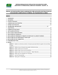
||||l|||||||l|lllllllllllll||l||lllllIllllIlllllllllIllllllllllllllllllllll
USO05155451A
United States Patent [191
[11]
[45]
Gladden et al.
DYNAMICALLY GENERATING A CLOCK
SIGNAL
[57]
[75] Inventors: Michael E. Gladden; William P.
LaViolette, both of Austin, Tex.
Oct. 13, 1992
ABSTRACT
A clock generator (30) dynamically generates a system
clock in response to a high or a low frequency oscilla
[73] Assignee: Motorola, Inc., Schaumburg, Ill.
tor. An ampli?ed oscillator input is provided to a first
input of a multiplexor (62), a divider (56), and a compar
ator circuit (58, 60). Divider (56) divides an oscillator
input frequency to provide a divided input to a second
[21] Appl. No.: 835,834
Feb. 18, 1992
[22] Filed:
[51] Int. Cl.5 ........................ .. H03L 7/06; H03L 7/18
[52] US. Cl. ................................... .. 331/1 A; 328/14;
input of multiplexer (62). Comparator circuit (58,60)
331/8; 331/14; 331/18; 331/116 FE
compares the input frequency with a reference fre
quency to determine whether the input frequency is
Field of Search ................... .. 331/1 A, l4, 18, 25,
high or low. If the input frequency is low, multiplexor
331/8, 116 FE; 328/14
[56]
5,155,451
Primary Examiner-Siegfried H. Grimm
Attorney, Agent, or Firm-Jonathan P. Meyer
[54] CIRCUIT AND METHOD FOR
[58]
Patent Number:
Date of Patent:
(62) is enabled to provide the oscillator input as the
system clock. If the input frequency is high, multiplexor
References Cited
U.S. PATENT DOCUMENTS
4,244,043
4,931,748
l/198l
6/1990
(62) provides the divided input as the system clock.
Additionally, comparator circuit (58,60) provides a
Fujita et a1. .................... .. 331/14 X
McDermott et al. ............ .. 331/1 A
control signal to enable an ampli?er (50) to amplify the
oscillator input using a high or low gain factor in accor
dance with the input frequency.
OTHER PUBLICATIONS
“MC68332 User’s Manual” published by Motorola, Inc.
in 1990, Section 4, pp. 4-4 to 4-53.
21 Claims, 5 Drawing Sheets
54
.
GAIN ENABLE
XTAL
Exmw.
AMPLIFIER
SYSTEM RESET
BUFFER
M
u
TL
I
I BUi‘FERED FREQUENCY
_5_g
p REEEQENcE
Fgg?g?gY E ‘
g
DIVIDER CHAIN
56
—
Q
R
CRYSTAL
Q
DETECT
EDGE
DETECT
xm.<——————
CLOCK ENABLE FREE)?“
CONTROL
DIVIDED
g
SYSTEM —’ DIYIDER
(*4) sYsTEN CLOCKT
CLOCK
f-
48
_
LIMP MODE
ENABLE
DETECT
-
SELECT
Q
‘ _f_
PowER 0N RESET
“
orfog’EisRET
US. Patent
Oct. 13, 1992
Sheet 1 of 5
5,155,451
SERIAL I/O PINS
l'""-"'___"'_—__?__—_____—___1
l
\
SERIAL INTERFACE
CPU 16
SIM
'------------J
)1
EXTERNAL
BUS PINS
76
EXTAL >—p
> XTAL
US. Patent
0a. 13, 1992
Sheet 2 of 5
5,155,451
owjEz mobjd
_whoims<“z.o
Mm
mcuzs<:
vm.
"M5E0H:. 5 2.
m <rm om
205Em30am
E5m.L5a
mm
h-NUB
US. Patent
Oct. 13, 1992
Sheet 5 of 5
5,155,451
“£2:58 5 5%."
5.5mEn
_
k
_
m
m
u
_
_
_
_
_
_
r
u
a
_
SmuhzmsoA
E85
zSNhoIHw‘-Em;o .m20E_i.mo<a
HEMoneu
2m5.~13w.a_ncw>:m
a.sm2uz5>o6m
zwhmfw am ze
mocm.Gmv
Ewomu sw.u_m<zow
M58 Em a NE .
cumwtn
Pow-Em
V
..@AUNB
1
5,155,451
CIRCUIT AND METHOD FOR DYNAMICALLY
GENERATING A CLOCK SIGNAL
circuit clock signal generator also includes a control
circuit. The control circuit has a ?rst input for receiving
the second reference signal and a second input for re
ceiving the ampli?ed signal. The control circuit pro- .
cesses each of the ampli?ed signal and second reference
signal to provide a ?rst control signal. A selector is
FIELD OF THE INVENTION
This invention relates generally to a data processing
system, and more particularly to a clock generator in a
data processing system.
BACKGROUND OF THE INVENTION
2
processing the ampli?ed signal to provide a second
clock signal having a third frequency. The integrated
coupled to the ampli?er means, the ?rst logic circuit,
10 and the control circuit for providing the ?rst clock
signal at either the ?rst frequency or the third frequency
Phase lock loop circuits are well known in the prior
art as clock generators which provide stable clock sig
in response to the ?rst control signal.
These and other features, and advantages, will be
more clearly understood from the following detailed
nals having predetermined, stable frequencies. The sta
bility of each frequency is provided as a result of an
iterative process which uses a feedback path to compare
description taken in conjunction with the accompany
an output of the phase lock loop circuit with an input
ing drawings. It is important to note the drawings are
not intended to represent the only form of the inven
signal typically provided by a crystal oscillator. Many
variations of the phase lock loop circuit have been de
veloped to provide improvements over known technol—
ogy. For example, US Pat. No. 4,931,748 provides a
circuit and a method for determining when the input
tion.
signal provided by the crystal oscillator is no longer
present. If the oscillator input to the phase lock loop
circuit data processor in accordance with one embodi
BRIEF DESCRIPTION OF THE DRAWINGS
FIG. 1 illustrates in block diagram form an integrated
ment of the present invention;
circuit is not detected, a special reference signal is pro
FIG. 2 illustrates in partial block diagram form a
vided to enable the phase lock loop circuit to continue 25 clock generator of the data processor of FIG. 1;
to provide the stable clock signal.
FIG. 3 illustrates in partial block diagram form an
Although phase lock loop circuits have been substan
oscillator generator and ampli?er of the clock generator
tially improved, several basic limitations still exist. For
of FIG. 2;
example, the locking time, or the period of time re
FIG. 4 illustrates in circuit diagram form an amplifier
quired for a phase lock loop circuit to provide a stable
of
the oscillator generator and ampli?er of FIG. 3;
signal after system start-up, is limited by both a fre
FIG. 5 illustrates in timing diagram form a ?rst clock
quency and an amplitude of the oscillator input signal.
generation operation in oscillator generator and ampli
An oscillator input signal with a lower frequency gener
?er of FIG. 3; and
ally requires more time to provide a signal having a
FIG. 6 illustrates in timing diagram form a second
35
detectable amplitude. Therefore, more time must pass,
clock generation operation in oscillator generator and
before the oscillator is able to provide a stable signal.
ampli?er of FIG. 3.
When an oscillator with a frequency of thirty-two kilo
hertz is used, a maximum locking time of several sec
DETAILED DESCRIPTION OF A PREFERRED
onds may be required to provide a stable system clock.
EMBODIMENT
In many applications, this delay is unacceptable. An
The present invention provides a phase lock loop
oscillator with a higher frequency may be used to de
circuit and method of operation which provide fast
crease the locking time to an acceptable period. How
locking times with minimal power consumption. Addi
ever, when an oscillator with a higher frequency is
tionally, the clock generator described herein allows a
used, the power consumption of the entire system is
increased.
45 user to derive a predetermined system clock signal
using one of a plurality of oscillators, each of which
Therefore, a need exists for a phase lock loop circuit
provides a different frequency. The present invention
which decreases locking times for a low frequency
allows the user to simply supply a different oscillator to
oscillator, but still uses a minimal amount of power.
Additionally, a user should not be limited to a single
input frequency, but should be provided with the ?exi
bility of using one of a plurality of frequencies depend
ing on an application of the system in which the phase
lock loop circuit is implemented. For example, the user
may choose between a phase lock loop circuit which
50
the input of the phase lock loop circuit and does not
require additional software or hardware control inputs.
Therefore, a user is provided with an uniquely ?exible
phase lock loop circuit which dynamically determines
an oscillator input frequency and subsequently provides
a system clock signal with a minimal amount of power
either consumes relatively little power, decreases lock 55 consumption depending on a frequency of the oscillator
input.
'
ing times for an external oscillator, or both.
The terms “assert” and “negate,” and various gram
SUMMARY OF THE INVENTION
matical forms thereof, are used to avoid confusion when
dealing with a mixture of “active high” and “active
The previously mentioned needs are ful?lled with the
present invention. Accordingly, there is provided, in 60 low” logic signals. “Assert” is used to refer to the ren
dering of a logic signal or register bit into its active, or
one form, an integrated circuit clock signal generator
for receiving a ?rst reference signal at a ?rst frequency
logically true, state. “Negate” is used to refer to the
and a second reference signal at a second frequency.
rendering of a logic signal or register bit into its inac
The integrated circuit clock signal generator provides a
tive, or logically false state.
?rst clock signal. The integrated circuit clock signal 65 FIG. 1 illustrates one implementation in which the
generator includes an ampli?er for receiving and ampli
clock generator circuit described herein may be used. In
fying the ?rst reference signal to provide an ampli?ed
this embodiment, the clock generator circuit provides a
signal. A ?rst logic circuit is coupled to the ampli?er for
system clock to an integrated circuit data processor 10.
3
5,155,451
Data processor 10 generally includes a oscillator crystal
11, a System Integration Module (SIM) 12, a timer
circuit 14, a Central Processing Unit (CPU) 16, a mem
ory circuit 18, serial interface 20, and an Inter-Module
Bus (IMB) 24. SIM 12, timer circuit 14, CPU 16, mem
ory circuit 18, and serial interface 20 are each bi-direc
4
parator 38 compares a frequency of each of the REF
ERENCE CLOCK and DIVIDE OUT signals and
provides a “PHASE ERROR" signal to an input of
charge pump and ?lter 42.
Loss of Crystal and Limp Mode Control circuit 36
provides a "FILTER ENABLE” signal and a “LIMP ,
MODE ENABLE” signal to a ?rst and a second con
tionally coupled to IMB 24 to communicate a plurality
of address, data, and control signals. Additionally,
memory 18 is bi-directionally coupled to timer circuit
trol input of charge pump and ?lter 42. Basically, Loss
of Crystal and Limp Mode Control circuit 36 indicates
when the EXTAL signal is no longer provided to clock
generator 30 and a special clock signal should be pro
14 to communicate data and control information. Serial
interface 20 is bi-directionally coupled to an external
data processor (not shown) via a plurality of serial in
put/output (I/O) pins to receive a ?rst plurality of ex
ternal information. Similarly, both timer circuit 14 and
SIM 12 are bi-directionally coupled to external devices
(not shown) via a plurality of timer pins and a plurality
of external bus pins, respectively. SIM 12 also receives
a VDD signal and a VDDSYN signal to respectively pro
vided to enable clock generator 30 to continue to pro
vide the SYSTEM CLOCK signal. U. S. Pat. No.
4,93l,748 discusses an implementation of the Loss of
Crystal and Limp Mode Control circuit 36 in greater
detail and is hereby incorporated herein by reference.
If the FILTER ENABLE signal is asserted, charge
pump and ?lter 42 ?lters the PHASE ERROR signal
and provides a ?ltered output at a ?rst voltage level to
crystal 11 receives a signal labelled “XTAL” from and 20 VCO 46. Similarly, if the LIMP MODE ENABLE
provides a signal labelled “EXTAL” to SIM 12.
signal is asserted, a ?rst logic circuit (not shown) in
During operation, SIM 12 generates a plurality of
charge pump and ?lter 42 charges and discharges ca
clock signals necessary for both data processor 10 and
pacitor 44 to provide a stable second voltage level to
all peripheral devices coupled to the plurality of exter
VCO 46. When either the FILTER ENABLE or
nal bus pins to function correctly together. The 25 LIMP MODE ENABLE signals are asserted, capacitor
VDDSYN signal is used to provide a separate power
44 and a resistor (not shown) in charge pump and ?lter
supply to a clock generator in SIM 12 such that noise
42 function to provide an RC ?lter circuit. The RC
and interference problems are reduced. Chapter 4 of the
?lter circuit ensures that the output provided to VCO
MC68332 User’s Manual published by Motorola, Inc. of
46 is stable and does not re?ect transients in the PHASE
Austin, Tex. in 1990, describes some of the conventional 30 ERROR signal. Additionally, in this implementation of
functions performed by SIM 12. However, the
the claimed invention, both the FILTER ENABLE
MC68332 User’s Manual does not describe the unique
and the LIMP MODE ENABLE signals may not be
functionality of SIM 12 as described herein.
simultaneously asserted. Circuitry necessary to charge
FIG. 2 illustrates in partial block diagram form a
and discharge capacitor 44 is well-known to one of
clock generator 30 of data processor 10 of FIG. 1. This
ordinary skill in the art and is, therefore, not explained
circuit, as previously mentioned, is located within SIM
in detail herein.
12. Clock generator 30 generally includes a divide chain
Upon receipt of either the ?ltered output or the limp
32, a prescaler 34, a Loss of Crystal and Limp Mode
mode frequency, VCO 46 provides the SYSTEM
Control circuit 36, a phase comparator 38, an oscillator
CLOCK signal to both external circuitry in data proces
generator and ampli?er 40, a charge pump and ?lter 42,
sor 10 and to the plurality of peripheral devices coupled
a capacitor 44, and a Voltage Controlled Oscillator
to the plurality of external bus pins. A frequency of the
(V CO) 46.
SYSTEM CLOCK signal is determined by a voltage
During operation, the EXTAL signal is provided to
level of the input of VCO 46. For example, assume the
an input of oscillator generator and ampli?er 40. Addi
PHASE ERROR signal indicates that the frequency of
tionally, the XTAL signal is output to oscillator crystal 45 the REFERENCE CLOCK signal is greater than the
1]. Generation of the XTAL signal is well known to
frequency of the DIVIDE OUT signal. Therefore,
one of ordinary skill in the art. Oscillator generator and
when the PHASE ERROR signal is ?ltered and pro
ampli?er 40 provides, as will be more fully described
vided to VCO 46, VCO 46 will increase the frequency
below, a “REFERENCE CLOCK” signal to a ?rst
of the SYSTEM CLOCK signal. The SYSTEM
input of phase comparator 38 in response to each of a 50 CLOCK signal is then sealed by prescaler 34 and di
“Power On Reset” (POR) signal, a “SYSTEM RE
vided to a lower frequency by divide chain 32 to at
SET” signal, and a “SYSTEM CLOCK” signal. The
tempt to match the frequency of the REFERENCE
REFERENCE CLOCK signal is also provided to an
CLOCK signal. Similarly, if the frequency of the REF
vide a power supply to data processor 10. Oscillator
input of Loss of Crystal and Limp Mode Control circuit
ERENCE CLOCK signal is less than the frequency of
36. The POR and SYSTEM RESET signals) respec 55 the DIVIDE OUT signal, the ?ltered PHASE ERROR
tively provide a ?rst and second control input to oscilla
signal will enable VCO 46 to decrease the frequency of
tor generator and ampli?er circuit 40. Both the POR
the SYSTEM CLOCK signal.
and SYSTEM RESET signals are asserted when data
In addition to providing the SYSTEM CLOCK sig
processor 10 is powered up or reset. The POR signal is
nal to external circuitry, VCO 46 also provides the
only asserted for a brief period of time at system start-up 60 SYSTEM CLOCK signal to prescaler 34 and to a sec
or reset, whereas the SYSTEM RESET signal is as
ond oscillator input of oscillator generator and ampli?er
serted for a longer period of time to ensure proper sys
v 40. Prescaler 34 scales the SYSTEM CLOCK signal
tem operation. Additionally, the SYSTEM RESET
signal may be asserted by a user of data processor 10 at
any point during operation that the user determines data
processor 10 should be reset.
Divide chain 32 provides an “DIVIDE OUT” signal
to a second input of phase comparator 38. Phase com
65
and provides a scaled clock signal to an input of divide
chain 32. Divide chain 32 subsequently divides the
scaled clock signal by a predetermined frequency to
provide the DIVIDE OUT signal at a lower frequency.
As was previously stated, the DIVIDE OUT signal is
provided to phase comparator 38.
5
5,155,451
6
As is illustrated in FIG. 2, clock generator 30 uses
feed-back to control the frequency of the SYSTEM
LIMP MODE ENABLE signal is provided to a fourth
CLOCK signal provided to external circuitry. The
frequency of the SYSTEM CLOCK signal is partially
determined by the REFERENCE CLOCK signal pro
vided by oscillator generator and ampli?er 40. In this
QUENCY and POR signals, divider chain 56 divides
the BUFFERED FREQUENCY signal by eight to
embodiment of the invention, the REFERENCE
frequency. In this implementation of the claimed inven
CLOCK signal typically has a frequency of thirty-two
kilohertz, an industry standard operating frequency.
Typical implementations of clock generators have been
developed to provide a predetermined clock frequency
tion, divider chain 56 has a divide ratio of eight to di
vide a four megahertz oscillator input down to a fre
quency of thirty-two kilohertz for use by data process
input of clock control circuit 58.
In response to each of the BUFFERED FRE
provide a DIVIDED FREQUENCY signal at a lower .
ing system 10.
using an EXTAL signal with a set frequency. However,
the locking time of clock generator 30 is dependent on
the frequency of the EXTAL signal. For example, if the
EXTAL signal has a frequency of thirty-two kilohertz,
Additionally, divider chain 56 uses a standard logic
circuit (not shown) to test the BUFFERED FRE
QUENCY signal to determine whether an oscillator 5
the locking time required to provide a stable SYSTEM
CLOCK signal with a minimal amount of power con
sumption is typically several seconds, a relatively long
period of time in a microprocessing environment. Simi
larly, if the EXTAL signal has a frequency of four 20
megahertz, the SYSTEM CLOCK signal is provided in
a relatively quick period of time of ?fty milliseconds.
However, the faster the frequency of the EXTAL sig
nal, the more power a clock generator will consume.
Therefore, a system designer must typically choose
between quick locking times or low power consump
tion when designing a data processing system using
conventional clock generator circuitry.
Clock generator 30 allows more ?exibility than tradi
tional phase lock loop implementations. Oscillator gen
erator and ampli?er 40 allows a user to determine
whether a fast or slow oscillator will be used to provide
frequency is provided via the XTAL signal. An output
of the standard logic circuit provides a CRYSTAL
DETECT signal to a ?fth input of clock control circuit
58 to indicate whether the oscillator frequency is pres
ent.
'
Clock control circuit 58 provides a EDGE DE
TECT ENABLE signal to a second input of frequency
edge detect 60 upon receipt of each of the BUFFERED
FREQUENCY, DIVIDED SYSTEM CLOCK, LIMP
MODE ENABLE, POR, and CRYSTAL DETECT
25
signals. Frequency edge detect 60 subsequently pro
vides a SELECT signal to a third input of multiplexer
62 and a ?rst input of NOR gate 54. The SYSTEM
RESET signal provides a second input to NOR gate 54.
NOR gate 54 asserts the GAIN ENABLE signal
when either the SYSTEM RESET or SELECT signals
is asserted. As was previously mentioned, the GAIN
the EXTAL signal. In particular, in the implementation
ENABLE signal is provided to ampli?er 50.
system power consumption. Additionally, oscillator
respectively labelled 64, 74, and 76. Additionally, ampli
the GAIN ENABLE signal will be subsequently dis
transistor 74 to provide the XTAL signal.
Ampli?er 50 is able to dynamically provide either a
of the invention described herein, the user may provide
high
gain or a low gain depending on either the fre
either a thirty-two kilohertz or a four megahertz oscilla 35
quency of the EXTAL signal or the SYSTEM RESET
tor to provide the EXTAL signal. Therefore, a user
signal. Ampli?er 50 is illustrated in greater detail in
may choose a four megahertz oscillator for faster lock
FIG. 4. Ampli?er 50 includes three p-type transistors,
ing times or a thirty-two kilohertz oscillator for lower
generator and ampli?er 40 allows a user to gain faster 40 ?er 50 also has three n-type transistors, respectively
labelled 66, 70, and 72. Ampli?er 50 also includes an
locking times during a system start-up of clock genera
inverter 68.
tor 30 without using a four megahertz oscillator. For
The EXTAL signal is provided to a control electrode
further details of oscillator generator and ampli?er 40,
of each of transistor 64, transistor 66, transistor 72, and
refer to FIG. 3.
FIG. 3 illustrates oscillator generator and ampli?er 45 transistor 74. The VDDSYN signal is connected to a ?rst
current electrode of transistor 64 and transistor 76. The
40 of FIG. 2. The basic components of this apparatus
?rst current electrodes of transistor 66 and transistor 70
are a divider 48, an ampli?er 50, a buffer 52, a NOR gate
are connected to a ground reference voltage. A second
54, a divider chain 56, a clock control circuit 58, a fre
current electrode of transistor 64 is connected to a sec
quency edge detect 60, and a multiplexor 62.
The EXTAL signal is provided to an oscillator input 50 ond current electrode of transistor 66. Additionally, a
second current electrode of transistor 64 is connected to
of ampli?er 50 and a GAIN ENABLE signal is pro
a ?rst current electrode of each of transistor 72 and
vided to a control input of ampli?er 50. Generation of
cussed in further detail.
Ampli?er 50 is coupled to an input of buffer 52 to
provide the XTAL signal. Additionally, ampli?er 50
The GAIN ENABLE signal is connected to a con
trol input of transistor 76 and an input of inverter 68. An
output of inverter 68 is connected to a control input of
transistor 70. A second current electrode of transistor
also provides the XTAL signal to an input of oscillator
70 is connected to a second current electrode of transis
crystal 11. Buffer 52 subsequently provides a BUFF
tor 72. Similarly, a second current electrode of transis
ERED FREQUENCY signal to a ?rst input of multi
plexor 62, a ?rst input of divider chain 56, and a ?rst 60 tor 74 is connected to a second current electrode of
input of clock control circuit 58.
transistor 76.
The SYSTEM CLOCK signal is provided to an input
Assume that during operation, the GAIN ENABLE
of divider 48. Subsequently, divider 48 is coupled to a
signal is negated to indicate that the XTAL signal has a
second input of clock control circuit 58 to provide a
frequency of thirty-two kilohertz and that a quick lock
signal labelled “DIVIDED SYSTEM CLOCK.” Simi 65 ing time is not necessary. Such a situation would occur
larly, the POR signal is provided to a second input of
if the user determined that power savings were of maxi
divider chain 56, a ?rst input of frequency edge detect
mum importance, and that an external system using data
60, and a third input of clock control circuit 58. The
processor 10 could tolerate a slow locking time.
7
5,155,451
' 8
In such a situation, a negated GAIN ENABLE signal
would turn transistor 76 off. Similarly, the output of
inverter 68 would not allow transistor 70 to be conduc
tive. If neither transistor 70 nor transistor 76 is enabled,
SYSTEM RESET signal enables ampli?er 50 to pro
vide the XTAL signal at a higher ampli?cation which
will substantially shorten the time necessary to generate
the SYSTEM CLOCK signal. Generation of the SE
LECT signal will be discussed later in further detail.
then neither transistor 72 nor transistor 74 may be en
abled. Therefore, ampli?er 50 may only amplify the
Assume in this example, that the SYSTEM RESET ,
signal is asserted at system start-up, and the XTAL
XTAL signal by a gain factor which is a function of
transistors 64 and 66. The ampli?ed EXTAL signal is
provided as the output labelled XTAL.
signal is provided at a same frequency of thirty-two
kilohertz, but with a higher gain.
Subsequently, the XTAL signal is buffered and
strengthened by buffer 52 to provide the BUFFERED
FREQUENCY signal at the thirty-two kilohertz fre
The gain supplied by transistors 72 and 74 is not ap
plied until the GAIN ENABLE signal is asserted. NOR
gate 54 asserts the GAIN ENABLE signal when either
the SELECT signal or the SYSTEM RESET signal is
asserted. If the GAIN ENABLE signal is asserted,
quency. As was previously described, the BUFFERED
FREQUENCY signal is provided to multiplexor 62,
transistors 70 and 76 are conductive. Subsequently,
transistors 72 and 74 are used in addition to transistors
divider chain 56, and clock control circuit 58. In divider
64 and 66 to amplify the EXTAL signal. Therefore, the
EXTAL signal is ampli?ed by a gain factor which is a
function of transistors 64, 66, 70, 72, 74, and 76. Subse
divided to a frequency of thirty-two kilohertz. A divide
ratio used by divider chain 56 is determined by a fre
quency of oscillator crystal 11. Therefore, it is useful for
quently, the resulting XTAL signal is ampli?ed even
chain 56, the BUFFERED FREQUENCY signal is
20
crystal oscillator 11 to provide the EXTAL frequency
more when the GAIN ENABLE signal is asserted.
which is divisible by two to the thirty-two kilohertz. In
As an example of the performance of clock generator
other systems in which the REFERENCE CLOCK
30, refer to FIG. 5. FIG. 5 illustrates a series of clock
signal might have a different frequency, the frequency
and control signals which enable clock generator 30 to
of oscillator crystal 11 must be carefully chosen for ease
provide the REFERENCE CLOCK signal at a prede 25 of computation and for minimal logic circuitry. Addi
termined frequency of thirty-two kilohertz with a faster
tionally, divider chain 56 tests the BUFFERED FRE
than normal locking time when the XTAL input is only
thirty-two kilohertz.
QUENCY signal to determine if a signal is actually
being provided by the XTAL signal. Depending on the
At the top of FIG. 5, a series of clock pulses repre
results of this test, the CRYSTAL DETECT signal is
either asserted or negated. As illustrated in FIG. 5, the
CRYSTAL DETECT signal is asserted to indicate that
the XTAL signal is present. The CRYSTAL DETECT
senting the SYSTEM CLOCK signal is provided. As
was previously mentioned, Loss of Crystal and Limp
Mode Control circuit 36 of FIG. 2 enables charge pump
and ?lter 42 to provide a limp mode frequency to VCO
46 if an EXTAL signal is not provided. Such is the case
when data processor 10 is ?rst powered up or is reset.
The limp mode frequency is determined by a charge
pump and ?lter 42. In the example described herein, the
signal is subsequently provided to clock control circuit
58. Clock control circuit 58 then synchronizes the
CRYSTAL DETECT signal to the DIVIDED SYS
TEM CLOCK signal to ensure proper operation of
clock generator 30. The synchronized CRYSTAL DE
TECT signal is labelled “SYNCHED CRYSTAL DE
limp mode frequency provided to VCO 46 results in a
SYSTEM CLOCK signal having a frequency of one
TECT.”
megahertz. A frequency of the SYSTEM CLOCK 40 Clock control logic 58 asserts a SET EDGE DE
signal is determined by a designer of clock generator 30
TECT signal on a rising edge of the SYNCHED
to fully meet the needs of data processor 10.
CRYSTAL DETECT signal. Upon receipt of each of
Divider 48 subsequently divides the frequency of the
SYSTEM CLOCK signal by four to provide the DI
the BUFFERED FREQUENCY, DIVIDED SYS
TEM CLOCK, CRYSTAL DETECT, LIMP MODE
VIDED SYSTEM CLOCK signal to clock control 45 ENABLE, and FOR signals, clock control circuit 58
circuit 58.
asserts the EDGE DETECT ENABLE signal on a
Concurrently, during either a system start-up or reset
rising edge of the SET EDGE DETECT signal. The
operation, an EXTAL signal is provided to ampli?er 50
EDGE DETECT ENABLE signal is subsequently
of oscillator generator and ampli?er 40. The GAIN
negated on a rising edge of a RESET EDGE DETECT
ENABLE signal is also provided to ampli?er 50. If the
ENABLE signal provided by clock control circuit 58.
GAIN ENABLE signal is asserted, ampli?er 50 ampli
The EDGE DETECT ENABLE signal enables fre
?es the EXTAL signal to provide the XTAL signal
quency edge detect 60 to count a number of rising edges
with a high gain. If the XTAL signal has a high gain,
of the BUFFERED FREQUENCY signal. In FIG. 5, a
clock generator 30 is able to provide the REFER
value counted by frequency edge detect 60 is indicated
ENCE CLOCK signal in a substantially shorter amount 55 by an EDGE DETECT STATE signal.
of time. However, the fast locking time requires more
The value is then compared against a predetermined
power consumption as additional logic circuitry (tran
sistors 70, 72, 74, and 76 of FIG. 4) must be powered to
provide greater ampli?cation and higher gain.
number to determine whether the BUFFERED FRE
QUENCY signal has a high or low frequency. A com
parator (not shown) at the output of frequency edge
The GAIN ENABLE signal may be asserted by 60 detect 60 may be used to perform such a function. If the
either the SYSTEM RESET signal or the SELECT
BUFFERED FREQUENCY signal has a low fre
signal. Typically, the SYSTEM RESET signal is only
quency, frequency edge detect 60 will only count a
asserted at system start-up when data processor 10 is
relatively small number of transitions. Similarly, if the
reset. If either signal is asserted, NOR gate 54 asserts the
BUFFERED FREQUENCY signal has a high fre
GAIN ENABLE signal. Therefore, during system 65 quency, frequency edge detect 60 will count a higher
start-up in this embodiment of the invention, the SYS
number of transitions.
TEM RESET signal is asserted. If the EXTAL signal
A SELECT PULSE signal is asserted on the falling
has a low frequency, such as thirty-two kilohertz, the
edge of the RESET EDGE DETECT ENABLE sig
5,155,451
10
nal to provide a control signal to evaluate the contents
CLOCK signal to ensure proper operation of clock
of frequency edge detect circuit 60. If the BUFFERED
generator 30. The synchronized CRYSTAL DETECT
signal is labelled “SYNCHED CRYSTAL DETECT.”
FREQUENCY signal is a low frequency, frequency
edge detect 60 negates the SELECT signal and pro
Clock control logic 58 asserts a SET EDGE DE
TECT signal on a rising edge of the SYNCHED
ways asserted when data processor 10 is either reset or
CRYSTAL DETECT signal. Upon receipt of each of ,
during system start-up. Therefore, if the frequency of
the BUFFERED FREQUENCY, DIVIDED SYS
crystal oscillator is thirty-two kilohertz, the SELECT
TEM CLOCK, CRYSTAL DETECT, LIMP MODE
signal must be negated to enable ampli?er 50 to provide
ENABLE, and RESET EDGE DETECT ENABLE
a correct gain factor. Additionally, the SELECT signal
signals, clock control circuit 58 asserts the EDGE DE
enables multiplexor 62 to select a correct signal as the
TECT ENABLE signal on a rising edge of the SET
REFERENCE CLOCK signal.
EDGE DETECT signal. The EDGE DETECT EN
Subsequently, multiplexer 62 selects the BUFF
ABLE signal is subsequently negated on a rising edge of
a RESET EDGE DETECT ENABLE signal provided
ERED FREQUENCY signal as an output, rather than
the DIVIDED FREQUENCY signal. The BUFF 15 by clock control circuit 58.
The EDGE DETECT ENABLE signal enables fre
ERED FREQUENCY signal is provided as the REF
ERENCE CLOCK signal to a remaining portion of
quency edge detect 60 to count a number of rising edges
clock generator 30 such that the phase lock loop opera
of the BUFFERED FREQUENCY signal. In FIG. 6, a
vides it to multiplexor 62. The SELECT signal is a]
tion previously described may be performed.
value counted by frequency edge detect 60 is indicated
If the BUFFERED FREQUENCY had been a high 20 by an EDGE DETECT STATE signal. When the
frequency, the SELECT signal is asserted to enable
SYSTEM CLOCK signal has a frequency, the binary
multiplexor 62 to provide the DIVIDED FRE
value of the EDGE DETECT STATE signal is seven.
The value is then compared against a predetermined
QUENCY signal as the REFERENCE CLOCK signal.
In either case, a REFERENCE CLOCK signal having
number to determine whether the BUFFERED FRE
a same predetermined frequency would be provided to 25 QUENCY signal has a high or low frequency. A com
a remaining portion of clock generator 30. In the exam
parator (not shown) at the output of frequency edge
ple described herein, the predetermined frequency is
detect 60 may be used to perform such a function. If the
thirty-two kilohertz'.
BUFFERED FREQUENCY signal has a low fre
FIG. 6 illustrates a series of clock and control signals
quency, frequency edge detect 60 will only count one
which enable clock generator 30 to provide the REF
transition. Similarly, if the BUFFERED FRE
ERENCE CLOCK signal at a predetermined fre
QUENCY signal has a high frequency, frequency edge
quency of thirty-two kilohertz when the frequency of
detect 60 will count seven transitions.
the EXTAL signal is four megahertz.
A SELECT PULSE signal is asserted on the falling
As in FIG. 5, FIG. 6 illustrates a series of clock pulses
edge of the RESET EDGE DETECT ENABLE sig
representing the SYSTEM CLOCK signal. In the ex
nal to provide a control signal to evaluate the contents
ample shown in FIG. 6, the SYSTEM‘ CLOCK signal
of frequency edge detect circuit 60. Because the BUFF
has a frequency of four megahertz.
ERED FREQUENCY signal is a high frequency of
four megahertz, frequency edge detect 60 does not
As was previously described, divider 48 subsequently
divides the frequency of the SYSTEM CLOCK signal
negate the SELECT signal. The SELECT signal is
by four to provide the DIVIDED SYSTEM CLOCK
provided to multiplexor 62 such that the DIVIDED
signal to clock control circuit 58. Concurrently, an
FREQUENCY signal is provided as an output. As de
EXTAL signal is provided to amplifier 50 of oscillator
scribed in FIG. 5, the REFERENCE CLOCK signal
generator and amplifier 40. The GAIN ENABLE sig
has a frequency of thirty-two kilohertz regardless of the
nal is also provided to ampli?er 50.
frequency of oscillator crystal 11. The BUFFERED
The GAIN ENABLE signal may be asserted by 45 FREQUENCY signal is provided as the REFER
either the SYSTEM RESET signal or the SELECT
ENCE CLOCK signal to a remaining portion of clock
signal. Generation of the SELECT signal will be dis
generator 30 such that the phase lock loop operation
cussed later in further detail. Assume in this example,
previously described may be performed.
that the SELECT signal is asserted at system start-up,
By providing the SELECT signal to indicate
and the XTAL signal is provided with a high gain.
50 whether the EXTAL signal is a high or low frequency
Subsequently, the XTAL signal is buffered and
signal, oscillator generator and ampli?er 40 is able to
strengthened by buffer 52 to provide the BUFFERED
dynamically provide the SYSTEM CLOCK signal at a
frequency of thirty-two kilohertz with no interaction
FREQUENCY signal at the four megahertz frequency.
As was previously described, the BUFFERED FRE
from the user. The SELECT signal enables multiplexor
QUENCY signal is provided to multiplexor 62, divider
62 to choose either the BUFFERED FREQUENCY
chain 56, and clock control circuit 58. In divider chain
signal or the DIVIDED FREQUENCY signal. If the
EXTAL signal is provided by a low frequency oscilla
56, the BUFFERED FREQUENCY signal is divided
to a frequency of thirty-two kilohertz. Additionally,
tor (not shown) equal to the desired frequency of data
processor 10, the REFERENCE CLOCK signal is
divider chain 56 tests the BUFFERED FREQUENCY
signal to determine if a signal is actually being provided 60 provided by a buffered form of the XTAL signal, the
by the XTAL signal. Depending on the results of this
BUFFERED FREQUENCY signal. Similarly, if the
test, the CRYSTAL DETECT signal is either asserted
EXTAL signal is provided by a high frequency oscilla
or negated. As illustrated in FIG. 6, the CRYSTAL
tor, the frequency of the EXTAL signal must be di
DETECT signal is asserted to indicate that the XTAL
vided to provide the REFERENCE CLOCK signal at
signal is present. The CRYSTAL DETECT signal is 65 the desired frequency of data processor 10.
subsequently provided to clock control circuit 58.
The SELECT signal is also provided to NOR gate 54
Clock control circuit 58 then synchronizes the CRYS
to dynamically assert or negate the GAIN ENABLE
TAL DETECT signal to the DIVIDED SYSTEM
signal. If the EXTAL signal has a low frequency, a high
11
5,155,451
12
gain is not necessary. Therefore, additional circuitry
typically required to amplify a high frequency may be
of the invention, it is to be clearly understood to those
turned off to conserve power consumption. The user of
skilled in the art that this description is made only by
the system is not required to interface with clock gener
ator 30 through either software or hardware circuitry to
the invention. Accordingly, it is intended, by the ap
While there have been described herein the principles
way of example and not as a limitation to the scope of
enable ampli?er 50 to provide the proper gain factor.
Rather, clock control circuit 58 and frequency edge
detect 60 determine a frequency of the EXTAL signal,
and provide the SELECT signal to dynamically enable
ampli?er 50 to provide the correct gain factor.
tion which fall within the true spirit and scope of the
invention.
We claim:
An additional feature of clock generator 30 allows
the SYSTEM RESET signal to be asserted when a fast
lock time is desired with a low frequency oscillator. The
receiving a ?rst reference signal at a ?rst frequency and
a second reference signal at a second frequency, the
pended claims, to cover all modi?cations of the inven- .
1. An integrated circuit clock signal generator for
integrated circuit clock signal generator providing a
?rst clock signal, the generator further comprising:
ampli?er means for receiving and amplifying the ?rst
reference signal to provide an ampli?ed signal;
SYSTEM RESET signal, however, is only asserted
when data processor 10 is reset or is powered up. The
SYSTEM RESET signal enables NOR gate 54 to assert
the GAIN ENABLE signal, such that the low fre
quency EXTAL'signal is further ampli?ed such that the
REFERENCE CLOCK signal may be generated more
quickly.
?rst logic means coupled to the ampli?er means for
processing the ampli?ed signal to provide a second
clock signal having a third frequency;
control means having a ?rst input for receiving the
second reference signal and a second input for
receiving the ampli?ed signal, the control means
20
In summary, clock generator 30 provides a very ?exi
ble circuit and method for providing a system clock to
a data processor. A user may provide either a high or
processing each of the ampli?ed signal and second
reference signal to provide a ?rst control signal;
low frequency oscillator depending on requirements of
the system in which the clock generator is used. The 25
user is not required to interface with the clock genera
tor; all decisions are made dynamically by the oscillator
generator and ampli?er circuit to effectively and effi
ciently use a provided oscillator signal. Additionally,
and
selector means coupled to the ampli?er means, the
?rst logic means, and the control means for provid
ing the ?rst clock signal at either the ?rst frequency
or the third frequency in response to the ?rst con
the user is also able to achieve fast lock times with a low 30
frequency oscillator by providing a single control sig
trol signal.
2. The integrated circuit clock signal generator of
nal, herein referred to as the SYSTEM RESET signal.
claim 1 wherein the ?rst control signal indicates a value
The clock generator circuit, therefore, allows three
modes of operation with only a single control signal. In
of the ?rst frequency of the ?rst reference signal.
3. The integrated circuit clock signal generator of
a ?rst mode, a low frequency oscillator may be used to 35 claim 1 wherein the ampli?er means further comprises:
provide a system clock with relatively little power con
?rst gain means for receiving and amplifying the ?rst
sumption. In a second mode, a high frequency oscillator
reference signal by a predetermined gain factor;
may be used to substantially decrease a period of lock
ing time and to provide a stable system clock in a rela
tively short amount of time. Lastly, in a third mode, the
user may also shorten the locking time period of a low
and
second gain means coupled to the ?rst gain means,
the second gain means selectively further amplify
ing the ?rst reference signal in response to the ?rst
power frequency oscillator by asserting a single control
control signal.
signal to enable more ampli?cation of the low power
4. The integrated circuit clock signal generator of
frequency.
claim 1 wherein the control means is further comprised
The implementation of the invention described herein 45 of:
is provided by way of example only. However, many
other implementations may exist for executing the func
tion described herein. For example, rather than just
choosing between a high and a low frequency, a plural
ity of oscillators with varying frequencies could be
a ?rst detector circuit coupled to the ampli?er means
for detecting a presence of the ampli?ed signal, the
?rst detector circuit providing a second control
signal to indicate the presence of the ampli?ed
50
implemented with the addition of more control and
signal.
5. The integrated circuit clock signal generator of
logic circuitry. Additionally, divider 48 may divide
frequency by any amount determined by the user. In
this embodiment of the invention, the SYSTEM
CLOCK signal was divided by four to be compatible 55
with the desired range of frequencies from thirty-two
claim 4 wherein the control means is further comprised
of:
a second divider circuit for dividing the second refer
ence signal to provide a divided frequency signal;
clock control means for providing a detect enable
kilohertz to four megahertz. Should a user decide to
signal in response to the divided frequency signal
provide oscillators having a different range of frequen
and the second control signal; and
cies, divider 48 will divide by a different number. For
a second detector circuit coupled to the clock control
example, if a user desired to choose between oscillators
means for receiving the detect enable signal, the
ranging from sixty-four kilohertz to thirty-two mega
hertz, divider 48 would divide by eight, rather than
second detector circuit detecting a number of tran
four. Similarly, more than one divider 48 could be im
plemented to broaden a range of possible oscillator
frequencies. Additionally, although described herein in
a phase lock loop circuit, oscillator generator and am
pli?er 40 may be implemented in a non-phase lock loop
system having a predetermined frequency.
65
sitions of the ampli?ed signal in response to the
detect enable signal, the second detector circuit
providing the ?rst control signal in response to the
number of transitions.
6. The integrated circuit clock signal generator of
claim 1 wherein the ?rst logic means is a ?rst divider
circuit, the ?rst divider circuit dividing the ampli?ed
13
5,155,451
signal to provide the second clock signal at the third
14
providing the ?rst control signal to indicate a value of
a
the second frequency of the ampli?ed signal.
7. The integrated circuit clock signal generator of
15. A phase lock loop circuit for generating a system
claim 1 wherein the third frequency of the second clock
clock signal in response to an oscillator input, compris
signal is less than the ?rst frequency of the ?rst refer 5 ing:
frequency.
ence signal.
8. The integrated circuit clock signal generator of
claim 1 further comprising:
second logic means for providing an ampli?er enable
a comparator having a ?rst input for receiving a ref- .
erence signal, the comparator also having a second
input for receiving a divided system clock signal,
signal to enable the ampli?er means to amplify the
?rst reference signal by a predetermined gain fac
the comparator providing an error signal indicat‘
ing a difference between the reference signal and
the divided system clock signal;
tor in response to both the ?rst control signal and a
a ?lter means for receiving the error signal and pro
third control signal, wherein the third control sig
viding a ?rst control signal;
a voltage controlled oscillator means for providing
the system clock signal in response to the ?rst con
nal indicates either a reset or a system start-up
operation.
9. A method for generating a ?rst clock signal having
a ?rst frequency comprising the steps of:
trol signal;
a divider means for dividing the system clock signal
receiving a ?rst reference signal at a second fre
to provide the divided system clock signal to the
quency;
second input of the comparator;
amplifying the ?rst reference signal by a predeter 2 O wherein the improvement comprises a clock generator
mined gain factor to provide an ampli?ed signal at
means, the clock generator means comprising:
the second frequency;
dividing the second frequency of the ampli?ed signal
to provide a divided signal at a third frequency, the
third frequency being less than the second fre
quency;
comparing the ?rst reference signal having the sec‘
ond frequency to a second reference signal having
a fourth frequency to provide a ?rst control signal; 30
and
providing the ?rst clock signal at either the second
ampli?er means for receiving and amplifying the
oscillator input to provide an ampli?ed signal;
?rst logic means coupled to the ampli?er means for
processing the ampli?ed signal to provide a ?rst
clock signal;
control means having a ?rst input for receiving the
system clock signal and a second input for receiv
ing the ampli?ed signal, the control means process
ing each of the system clock signal and the ampli
?ed signal to provide a second control signal; and
frequency or the third frequency in response to a
a multiplexor coupled to the ampli?er means, the ?rst
value of the ?rst control signal.
logic means, and the control means for providing
10. The method of claim 9 wherein the step of ampli .35
either the ampli?ed signal or the ?rst clock signal
fying the reference signal further comprises the steps of:
as the reference signal in response to the second
amplifying the ?rst reference signal by a predeter
control signal.
mined gain factor to provide an intermediate ampli
16. The phase lock loop circuit of claim 15 wherein
?ed signal; and
the ampli?er means further comprises:
selectively further amplifying the intermediate ampli
?rst gain means for receiving and amplifying the
?ed signal in response to the ?rst control signal to
oscillator input by a predetermined gain factor; and
provide the ampli?ed signal.
_
second gain means coupled to the ?rst gain means,
11. The method of claim 10 further comprising the
the second gain means selectively further amplify
steps of:
I
ing the oscillator input in response to the second
detecting a presence of the ampli?ed signal; and
control signal.
45
providing a second control signal to indicate the
17. The phase lock loop circuit of claim 15 wherein
presence of the ampli?ed signal.
the control means is further comprised of:
12. The method of claim 11 further comprising the
a ?rst detector circuit coupled to the ampli?er means
steps of:
for detecting a presence of the ampli?ed signal, the
dividing the ?rst clock signal to provide a divided 50
?rst detector circuit providing a third control sig
frequency;
nal to indicate the presence of the ampli?ed signal;
providing a detect enable signal in response to the
a second divider circuit for dividing the system clock
divided frequency and the second control signal;
signal to provide a divided frequency signal;
and
detecting a number of transitions of the ampli?ed 55
signal in response the detect enable signal, the
value of the ?rst control signal being determined
by the number of transitions of the ampli?ed signal.
13. The method of claim 9 further comprising the step
Of:
providing an ampli?er enable signal to enable the
ampli?er means to amplify the ?rst reference signal
by a predetermined gain factor in response to both
the ?rst control signal and a third control signal,
wherein the third control signal indicates either a
reset or a system start-up operation.
14. The method of claim 9 wherein the step of com
paring the ?rst reference signal is further comprised of
clock control means for providing a detect enable
signal in response to the divided frequency signal
and the third control signal; and
a second detector circuit coupled to the clock control
means for receiving the detect enable signal, the
second detector circuit detecting a number of tran
sitions of the ampli?ed signal in response to the
detect enable signal, the second detector circuit
providing the second control signal in response to
the number of transitions.
18. The phase lock loop circuit of claim 15 wherein
the second control signal indicates a frequency of the
ampli?ed signal.
19. The phase lock loop circuit of claim 15 wherein
the ?rst logic means is a ?rst divider circuit, the ?rst
15
5,155,451
divider circuit dividing the ampli?ed signal to provide
the ?rst clock signal.
16
a divider having an input coupled to the ampli?er and
a divided output;
a clock control circuit having a ?rst input coupled to
20. The phase lock loop circuit of claim 15 further
comprising:
the ampli?er, a second input coupled to the di
second logic means for providing an ampli?er enable
signal to enable the ampli?er means to amplify the
vider, and a third input coupled to an external
control signal, the clock control circuit having an
oscillator input by a predetermined gain factor in
output;
response to both the second control signal and a
a frequency detector having a ?rst input coupled to
fourth control signal, wherein the fourth control
the clock control circuit and a second input cou
signal indicates either a reset or a system start-up 10
operation.
pled to the external control signal, the frequency
detector having an output; and
a multiplexor having a ?rst input coupled to the am
pli?er, a second input coupled to the divider, and a
21. An integrated circuit clock signal generator, com
prising:
an oscillator having an output;
third input coupled to the frequency detector, the
an ampli?er having a first input coupled to the oscilla
multiplexer having an output.
tor and an output;
*
25
30
35
45
55
65
i
i
*
i