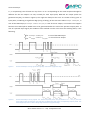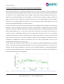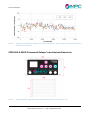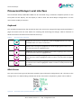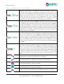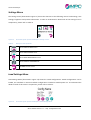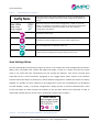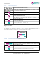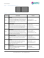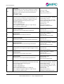
1
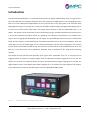
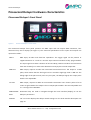
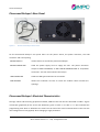
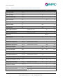
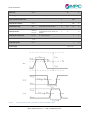
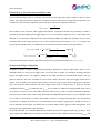
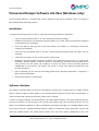
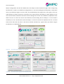
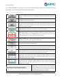
MICRO PHOTON DEVICES PSD Picosecond Delayer $PSD-065-A-MOD © Micro Photon Devices S.r.l. Via Stradivari, 4 39100 Bolzano (BZ), Italy email info@micro-‐‑photon-‐‑devices.com Phone +39 0471 051212 • Fax +39 0471 501524 Picosecond Delayer User Manual Version 6.0.1 -‐‑ January 2015 Picosecond Delayer Table of Contents INTRODUCTION 4 PICOSECOND DELAYER HARDWARE CHARACTERISTICS 5 Picosecond Delayer’s Front Panel 5 Picosecond Delayer’s Rear Panel 6 Picosecond Delayer’s Electrical Characteristics 6 Calculation of the maximum repetition rate 9 Picosecond Delayer Operation 9 11 Picosecond Delayer precision and temperature dependence $PSD-‐065-‐A-‐MOD Picosecond Delayer’s mechanical dimensions 12 PICOSECOND DELAYER LOCAL INTERFACE 13 Keyboard 13 Main Screen 13 Settings Menu 15 Load Settings Menu 15 Save Settings Menu 16 Brightness Menu 17 PICOSECOND DELAYER SOFTWARE INTERFACE (WINDOWS ONLY) 18 Installation 18 Software Interface 18 .. 2 Micro Photon Devices S.r.l. – Italy All Rights Reserved Picosecond Delayer PICOSECOND DELAYER SERIAL COMMANDS 21 Picosecond Delayer Serial Commands Error 24 PICOSECOND DELAYER (LINUX AND MAC OS X) 25 DIFFERENCES BETWEEN HW V5 (OR HIGHER) AND HW V4 26 SYSTEM REQUIREMENTS 26 COPYRIGHT AND DISCLAIMER 26 .. 3 Micro Photon Devices S.r.l. – Italy All Rights Reserved Picosecond Delayer Introduction The MPD Picosecond Delayer is a solid-‐state delayer based on programmable-‐delay chips. Any signal that is fed in the SMA input is reshaped, delayed in time and routed to the SMA outputs. The reshaping generates both a TTL and a NIM pulse independently on the type and form of the input pulse. The minimum delay (Propagation Delay) is on average 15 ns. The user-‐selectable additional delay (Programmable Delay) can be set from 0 ns to 50 ns within 10 ps steps. The output pulses duration is also user adjustable from 1 ns to 250 ns. The delayer can be set directly on the instrument by using a membrane keyboard and a color LCD or it can be also operated via USB by means of a graphical user interface (GUI) software. This software runs only on PCs running Microsoft Windows® XP® or higher. The provided device drivers install a “Virtual Serial COM” and the delayer is controlled by plain text ASCII commands sent to the correct COM port. Since the commands are here provided (page 21), the Picosecond Delayer can be easily integrated in any custom control software and experimental set-‐up. Also, because the device drivers are provided also for Linux and Mac Os X, the instrument can be effectively operated with no problem by PCs using these operating systems. The delayer accepts periodic and aperiodic input signals with amplitudes from -‐2V to +3V and can be triggered either on positive or negative edges, with an adjustable threshold ranging from -‐2V to +2V. The delayer can act also as a frequency divider by a user selectable positive integer ranging from 1 to 999. The digital outputs have a controllable pulse width ranging from 1 ns to 250 ns for both NIM and TTL outputs. Input and outputs connectors are SMA. Figure 1 shown $PSD-‐065-‐A-‐MOD model. Figure 1. Picosecond Delayer model $PSD-‐065-‐A-‐MOD. .. 4 Micro Photon Devices S.r.l. – Italy All Rights Reserved Picosecond Delayer Picosecond Delayer hardware characteristics Picosecond Delayer’s Front Panel Figure 2. Picosecond Delayer’s Front Panel. The Picosecond Delayer front panel presents one SMA input and two output SMA connectors, four directional keys and a display (see Figure 1). The electrical specifications of the inputs and outputs are reported in Table 1. INPUT SMA input, 50 Ohm with fixed DC impedance. The trigger signal can be positive or negative between -‐2 V and +3 V and the input internal threshold is fully programmable. The input signal must have a duration of at least 100 ps, 100 mV overdrive and a minimum slew rate of 100 V/µs in order to be detected correctly by the internal comparator. NIM OUT SMA output, requires 50 Ohm DC terminated transmission lines. The output is a NIM pulse, which means that the low logic level is 0 V and the high logic level is -‐800 mV. The falling edge of the pulse marks, with very low jitter, the delayed signal; the output pulse width is user adjustable. TLL OUT SMA output, requires 50 Ohm DC terminated transmission lines. Electric pulses of 3.3V LVTTL are generated at this output. The TTL output pulse width is also user adjustable and it is 1 ns larger than NIM OUT. DIRECTIONAL Directional keys are used to navigate through the local interface (display) to set the KEYS delayer’s parameters. DISPLAY 1.8” TFT screen displays the delayer actual settings. For the local interface description see page 13. .. 5 Micro Photon Devices S.r.l. – Italy All Rights Reserved Picosecond Delayer Picosecond Delayer’s Rear Panel Figure 3. Picosecond Delayer’s Rear Panel. On the Picosecond Delayer’s rear panel there are the power switch, the power connector, the USB connector and a fan opening. POWER SWITCH used to switch on and off the picosecond delayer. POWER CONNECTOR holds the power supply cord to supply the unit. The power connector accepts a LEMO FFG.0B.302, an ODU S20L0C-‐P02MJG0-‐520S or compatible connectors. The red mark indicates the 12V pin. USB CONNECTOR holds the USB type-‐B cable for PC connection. FAN OPENING allows the circulation of fresh air inside the module. Never occlude the openings. Picosecond Delayer’s Electrical Characteristics The logic values and the timing properties of INPUT, NIM OUT and TTL OUT are described in Table 1. Figure 4 illustrates graphically all the terms and definitions given in Table 1. In Table 1, it is also indicated the programming time which is defined as the time from the end of the serial communication to the time the new configuration is fully applied, when changing a single parameter. .. 6 Micro Photon Devices S.r.l. – Italy All Rights Reserved Picosecond Delayer Table 1. Electrical Characteristics of the Picosecond Delayer input and outputs. Parameter Symbol Description Min. Typ. Max. Unit Input high voltage VIN_High 3 V Input low voltage VIN_low -‐2 V Input differential range VD,MAX -‐2 2 V Input termination RIN 50 Ω Input voltage overdrive VOV 100 mV Input pulse width tIN 100 ps Input Slew Rate SR 100 V/µs Input overdrive dispersion 100 mV < VOV < 1 V 10 ps Input slew rate dispersion 2 V/ns < SR < 10 V/ns 15 ps Input Edge Neg/pos Input Threshold VTH -‐2 2 V Input threshold resolution ΔVTH 10 18 30 mV NIM Output low logic level VNIM_High 50 Ω termination required 0 V NIM Output high logic level VNIM_Low 50 Ω termination required -‐800 mV NIM Output Bandwidth BWNIM 300 380 MHz TTL Output Bandwidth BWTTL 100 120 MHz TTL Output low logic level VTTL_Low 50 Ω termination required 0 V TTL Output high logic level VTTL_High 50 Ω termination required 2.4 V Propagation delay INPUT -‐ NIM OUT tPD_NIM 12 15 18 ns Propagation delay INPUT -‐ TTL OUT tPD_TTL 16 19 22 ns Delay programmable range tRANGE Equivalent to tDELAY (max) 45 50 55 ns 75 ps/°C tDELAY = 0 ns 2 5 ps tDELAY = trange 5 12 ps Delay programmable Temperature variation Random timing jitter (RMS) range ΔtRANGE (T) Rtjitter .. 7 Micro Photon Devices S.r.l. – Italy All Rights Reserved Picosecond Delayer Delay step ΔtDELAY Delay integral non linearity INL Full scale range Input frequency divider factor OUTPUT pulse duration 10 ps -‐100 50 ps 1 999 tOUTPUT 1 250 ns OUTPUT pulse step ΔtOUT Pulse width incremental step 3 3.3 3.5 ns OUTPUT off time tNIM_OFF, tTTL_OFF tNIM_OFF 1 3 ns OUTPUT pulse width jitter tOUT,jitter % of pulse duration 1 % OUTPUT pulse width INL tOUT,INL Programming time tPROG Power supply and tTTL_OFF are not guaranteed to be the equal on a module. max (±5%, 1 ns) 1 ms 12 V – 1 A Figure 4. Timing NIM OUT and TTL OUT whit respect to the INPUT signal. .. 8 Micro Photon Devices S.r.l. – Italy All Rights Reserved Picosecond Delayer Calculation of the maximum repetition rate The picosecond delayer input is internally connected to a fast comparator whose output is fed to a pulse shaper. The input pulse duration (tIN) is thus totally un-‐related to the internal reshaped-‐pulse duration. As a consequence, the maximum repetition rate at the input side can be calculated as follows: 𝑓!"#!!"#$% = 1 𝑡!" + 100 𝑝𝑠 where 100 ps is the minimum, both negative and positive, input pulse duration (tIN) according to Table 1. Considering the NIM output pulse length equal to toutput, the maximum repetition rate, at the output side, depends on the maximum frequency of the selected output (BWNIM for NIM OUT and BWTTL for TTL OUT), on the duration of the output pulse (toutput), on the minimum output off time (tNIM_OFF or tTTL_OFF) and on the input frequency divider factor n. It follows that the maximum repetition rate, at the output side is: 1 1 𝑓!"#!!"#$"#,!"# = × 𝑚𝑖𝑛 , BW!"# 𝑛 𝑡!"#$"# + 𝑡!"#!!"" 1 1 𝑓!"#!!"#$"#,!!" = × min , 𝐵𝑊!!" 𝑛 (𝑡!"#$"# + 1 𝑛𝑠) + 𝑡!!"!!"" The picosecond delayer maximum repetition rate is than the minimum between fmax-‐input , fmax-‐output. Picosecond Delayer Operation Normally, as shown in Figure 5, the Picosecond Delayer generates an output digital pulse, with an user-‐ adjustable delay, for every input trigger event. As can be seen in Figure 5, the delayer actually generates always two digital pulses one negative, based on the NIM standard at the NIM OUT output, and one positive, based on the LVTTL standard at the TTL OUT output. Of course the input trigger period can be shorter than set delay: the module simply delays in time the input pulses while keeping their repetition rate. The minimum delay between an input trigger event and an output pulse is given by intrinsic propagation delay (tPD_NIM for NIM OUT and tPD_TTL for TTL OUT). An additional programmable delay can be set by the user from 0 ns to an achievable maximum value (tRANGE), in order to have the desired total delay. Users can also set the output pulses width. Particularly the NIM OUT pulse width (tOUTPUT) is adjustable from 1 ns to 250 ns in fixed steps; TTL-‐OUT’s pulse width is always 1 ns longer than NIM OUT’s one. The delayer can also act as a frequency divider by a user selectable positive integer ranging from 1 to 999; of course, in case of aperiodic input signals, the divider acts as a pulse skipper where, given n the dividing factor, (n-‐1) input pulses are skipped after each valid input. As already specified, the minimum INPUT pulse width for positive and negative pulses (tin) is 100 ps. After every output pulse, NIM and TTL outputs are off for a period of time, called minimum off time (tNIM_OFF and .. 9 Micro Photon Devices S.r.l. – Italy All Rights Reserved Picosecond Delayer tTTL_OFF respectively). This off-‐time can vary from 1 ns to 3 ns depending on the actual sample and might be different for the two outputs. As said, normally for each input pulse, NIM and TTL output pulses are generated. Anyway, as shown in Figure 6, this might not always be the case. As a matter of fact, given an input pulse, considering its significant edge (rising or falling), all the next ones within 𝑡!"#$"# + 𝑡!"#_!"" , in case of the NIM output, or 𝑡!"#$"# + 1𝑛𝑠 + 𝑡!!"_!"" , in case of the TTL output, are masked. This happens because the masked pulses would have to be generated before the end of the previous output pulse. In case of a periodic input signal, the condition to be satisfied in order not to have the masking effect, is the following: 1 𝑓𝑖𝑛 > 𝑡!"#$"# + 𝑡!"#_!"" in case of the NIM output 1 𝑓𝑖𝑛 > 𝑡!"#$"# + 1𝑛𝑠 + 𝑡!!"_!"" in case of the TTL output Figure 5. Picosecond Delayer timing signals. Rising edge selected as significant edge. Figure 6. Picosecond Delayer timing signals. The third and fourth pulses are fed within tOUTPUT + tNIM_OFF from the rising edge of the second pulse (t2) and thus the NIM OUT hides their corresponding output pulses. The same happens for the TTL OUT. Rising edge selected as significant edge. .. 10 Micro Photon Devices S.r.l. – Italy All Rights Reserved Picosecond Delayer Picosecond Delayer precision and temperature dependence The Picosecond Delayer has a nominal step delay of 10 ps. In order to reduce as much as possible the integral non-‐linearity and the differential non-‐linearity each instrument is fully characterized and calibrated. As a result the curve, measured-‐delay versus set-‐delay, is almost ideal and the integral non-‐linearity error, defined as the measured-‐delay minus the set-‐delay, as a function of the set-‐delay, is always smaller than 100ps in absolute values. Actually, the excellent linearity of the curve measured-‐delay versus set-‐delay is proved by the very good integral non-‐linearity error of about (peak to peak) +50ps/-‐100ps over the full range of the programmable delays, as shown in Figure 7. As any electronic device, the Picosecond Delayer experiences propagation delay changes with temperature variations. In order to mitigate the effects of the latter, the temperature is stabilized by means of variable speed fan inserted in a thermal control loop. After the initial warm-‐up, the operating temperature of the delayer board stabilizes at 55 °C. This value is kept then constant by the thermal control loop with an accuracy of ±0.2 °C. Additionally, whenever the set temperature cannot be kept at 55 °C, the delayer compensates the delay as a function of temperature to reduce delay variations in order to keep the same state of the art performances as shown in example in Figure 8 at three different temperatures. Even if temperature compensations maintain extraordinary INLs, the delay programmable range can’t be compensated and it varies at a rate of 75 ps/°C. For this reasons the set-‐delay can be set from 0 to the temperature dependent MAX-‐DELAY. Actual MAX-‐ DELAY is constantly hardware updated depending on the actual Delayer temperature. This value can be requested to the Picosecond Delayer by using the serial commands explained in a following paragraphs. Instead, the actual MAX-‐DELAY value is already taken into account when using either the SW interface or the Local Interface (see the next paragraph). Figure 7. Typical Picosecond Delayer integral non linearity error (INL) as a function of the set delay after calibration. .. 11 Micro Photon Devices S.r.l. – Italy All Rights Reserved Picosecond Delayer Figure 8. Typical Picosecond Delayer integral non linearity error (INL) as a function of the set delay after calibration at different temperatures. $PSD-‐065-‐A-‐MOD Picosecond Delayer’s mechanical dimensions Figure 9. Picosecond Delayer $PSD-‐065-‐A-‐MOD mechanical dimensions. All dimensions in mm. .. 12 Micro Photon Devices S.r.l. – Italy All Rights Reserved Picosecond Delayer Picosecond Delayer Local interface The Picosecond Delayer $PSD-‐065-‐A-‐MOD can be controlled using a membrane keyboard present on the front panel and TFT display. The TFT display is used to show the actual delayer configuration or all the menu used to modify an control it. Keyboard The membrane keyboard has four directional keys that are used to navigate through picosecond delayer’s pages and menus and one enter button for selecting and confirming the changes. Table 2 illustrates in detail the functions of the directional and the enter keys. Table 2. Directional keys explained. ENTER KEY: Used to place in modification mode the highlighted item or to confirm a modified value or to enter in a sub-‐menu. UP KEY: used to change the highlighted item while navigating inside a menu or to increment the value of a highlighted item. DOWN KEY: used to change the highlighted item while navigating inside a menus or to decrement the value of a highlighted item. LEFT KEY: used to change the highlighted item while navigating inside a menu or to move the cursor inside a highlighted number in order to correctly select the digit to modify. RIGHT KEY. used to change the highlighted item while navigating inside a menu or to move the cursor inside a highlighted number in order to correctly select the digit to modify. Main Screen The main screen (see Figure 10) illustrates possible input and output configurations and a shortcut to the settings menu. For understanding in detail each of the main menu’s components, please refer to Table 3. Figure 10. Screenshot of the picosecond delayer’s main screen. .. 13 Micro Photon Devices S.r.l. – Italy All Rights Reserved Picosecond Delayer Table 3. Main (Delayer parameters) screen explained. Displays the delay set (tDELAY). The delay value has grey colour when in OFF state, a green colour if the outputs are enabled and a red colour if the last value set is not valid. If this row is highlighted, by pressing the ENTER KEY, the delay value can be changed. By pressing the LEFT KEY or the RIGHT KEY, the digit to be modified is selected and with the UP KEY and the DOWN KEY the digit is actually increased/decreased. During delay value modification, it is not possible to change any parameter on the main screen by serial commands (delayer in Local Mode). Displays the NIM OUT pulse width (tOUTPUT). TLL OUT pulse width is 1 ns larger than this value. Pulse value has grey colour when in OFF state, green colour if the outputs are enabled and red colour if the last value set is not valid. If this row is highlighted, by pressing the ENTER KEY, the output pulse width can be changed. By pressing the LEFT KEY or the RIGHT KEY, the digit to be modified is selected and with the UP KEY and the DOWN KEY the digit is actually increased/decreased. During pulse width value modification, it is not possible to change any parameter on the main screen by serial commands (delayer in Local Mode). Displays the threshold level of the input discriminator. The value has grey colour when in OFF STATE, green colour if the outputs are enabled and red colour if the last value set in not valid. If this row is highlighted, by pressing the ENTER KEY, the threshold level value can be changed. By pressing the LEFT KEY or the RIGHT KEY, the digit to be modified is selected and with the UP KEY and the DOWN KEY the digit is actually increased/decreased. During threshold level value modification, it is not possible to change any parameter on the main screen by serial commands (delayer in Local Mode). Displays the actual delayer’s input frequency divider factor. The value has grey colour when in OFF STATE, green colour if the outputs are enabled and red colour if the last value set in not valid. If this row is highlighted, by pressing the ENTER KEY, the frequency divider factor can be changed. By pressing the LEFT KEY or the RIGHT KEY, the digit to be modified is selected and with the UP KEY and the DOWN KEY the digit is actually increased/decreased. During divider factor modification, it is not possible to change any parameter on the main screen by serial commands (delayer in Local Mode). FALLING EDGE. Identify the falling edge of the input signal as trigger edge. By Pressing the ENTER KEY the significant edge changes to the rising edge. RISING EDGE. Identify the rising edge of the input signal as the trigger edge. By pressing the ENTER KEY the significant edge changes to the falling edge. OFF STATE. When this icon is shown, the NIM OUT and the TTL OUT are disabled. By pressing the ENTER KEY the outputs are enabled. ON STATE. When this icon is shown the NIM OUT and TTL OUT are enabled. By pressing the ENTER KEY, the outputs are disabled. SETTINGS. By pressing the ENTER KEY, the Settings Menu is shown on the display. .. 14 Micro Photon Devices S.r.l. – Italy All Rights Reserved Picosecond Delayer Settings Menu The settings menu (illustrated in Figure 11) shows the shortcuts to the following menus: load settings, save settings, brightness and product information. In order to understand in detail each of the settings menu’s components, please refer to Table 4. Figure 11. Screenshot of the picosecond delayer’s settings screen. Table 4. Settings screen explained. Go to LOAD SETTINGS menu. Go to SAVE SETTINGS menu. Go to BRIGHTNESS DISPLAY menu. Show PRODUCT INFORMATION Go BACK to main screen Load Settings Menu Load Settings Menu (illustrated in Figure 12) shows the saved configurations. Saved configurations can be loaded, set as default or removed. Default configuration is loaded at module power on. To understand the details of each of this menu’s components, please refer to Table 5. Figure 12. Screenshot of the picosecond delayer’s Load Settings Menu. .. 15 Micro Photon Devices S.r.l. – Italy All Rights Reserved Picosecond Delayer Table 5. Load Settings Menu explained. Shows the name of the saved configuration. If the row is highlighted, by pressing the LEFT or RIGHT buttons, the saved configurations’ names are cycled. Shows the parameters of the saved configuration, named on top of the display. The “Default” word appears only if the actual saved configuration has been made default. Brand new delayers come with a default configuration preinstalled. Goes back to main menu. Removes the actual configuration from the saved configurations. Sets the configuration as default at power-‐up. Loads the shown configuration and goes back to main screen. Save Settings Menu The Save Settings Menu (illustrated in Figure 13) stores in the module the actual configuration parameters (Delay, Pulse, Threshold Level, Divider and edge) and assigns a name to it. Please note that the output status is not saved and must controlled by the user through the delayer’s main screen, the EOx serial command (see the “serial commands” paragraph) or the “toggle output status” button of the software interface. When the delayer is powered on, and the default configuration is loaded, the outputs are always disabled. It is possible to save a maximum of 10 configurations. These are not editable but can be deleted or made “default”. Finally, a “PC saved” configuration is always present, it cannot be deleted and it is used to save the default one when using the PC software or the “SS” (Save Status) serial command. In order to understand in detail each one of this menu’s components, please refer to Table 6. Figure 13. Screenshot of the picosecond delayer’s Save Settings Menu. .. 16 Micro Photon Devices S.r.l. – Italy All Rights Reserved Picosecond Delayer Table 6. Save Settings Menu explained. Shows the name of the configuration to save. LETTERS. Using directional keys the highlighted letter can be changed as selected for composing the configuration name. Goes back to Settings Screen. Removes the last character inserted. SHIFT OFF. By pressing the ENTER KEY, the capital letters are shown and the icon changes to the SHIFT ON one. SHIFT ON. By pressing the ENTER KEY, minuscule letters are shown and the icon changes to the SHIFT OFF one. Saves the configuration with the entered name. Brightness Menu The Brightness Menu (illustrated in Figure 14) is used to modify the display brightness. In order to understand in detail each one of this menu’s components, please refer to Table 7. Figure 14. Screenshot of the picosecond delayer’s Brightness Menu. Table 7. Brightness Menu explained. Brightness intensity bar. When it is highlighted, use the LEFT and RIGHT KEYS for decreasing or increasing the brightness. If brightness is null the display is off and only the RIGHT KEY is enabled. Goes back to Settings Screen without saving the actual brightness intensity. Saves the brightness intensity and goes back to the settings menu. .. 17 Micro Photon Devices S.r.l. – Italy All Rights Reserved Picosecond Delayer Picosecond Delayer Software interface (Windows only) The Picosecond Delayer is provided with a basic acquisition and control software, which is running on Microsoft Windows operating systems. Installation Complete the following steps in order to install the controlling software for Windows®: • Log in as system administrator or as a user with administration privileges. • Disable any automatic virus detection programs before you install. Some virus detection programs could interfere with installation. • Insert the USB key and copy the zip file that contains the installer in a temporary location (for example your Desktop) • Unzip the file and double click on the file named setup.exe located inside the folder you just unzipped. • Follow the instructions on the screen until the installer ends. • Windows® will automatically recognize the device and install the correct drivers. If a “found new hardware” window appears, select the option to automatically download recommended drivers from internet. For this reason, the computer on which the drivers will be installed, MUST BE CONNECTED to the internet. The drivers will create a virtual serial COM associated with the Picosecond Delayer. • Once completed, you can start the controlling software from Windows Start Menu Programs MPDPicosecond Delayer. • Remove the temporary install folder. Software Interface The software interface allows the control of the delayer settings with a simple and user friendly window, which is shown in Figure 15 and in Figure 16. The window shows always the current status of the delayer. In order to understand in detail the interface, please refer to Table 8. In order to change the delay, the threshold level, the output pulse duration or the input frequency divider, the desired value(s) can be inserted in the correct input box(es) and, after pressing the enter key, the delayer is immediately updated. In order to modify the input signal valid edge, the “CHANGE EDGE” button has to be pressed. The “TOGGLE OUTPUT STATUS” enables or disable the output generation. A green LED marks the enabled output. The “SAVE STAUS” button saves the entire delayer configuration: this is the .. 18 Micro Photon Devices S.r.l. – Italy All Rights Reserved Picosecond Delayer delayer configuration that will be loaded when the delayer will be switched on again after having being switched off. In order to save different configurations on a PC and recalling them afterwards, a drop-‐down menu is provided (see Figure 16 on the left). The provided help menu (Figure 16 on the right) is also very useful because it allows to open the instrument user manual and the possibility to check updates for the user manual and the software to the latest version through the internet. The ‘COM Port’ dropdown-‐list box allows the user to select the correct serial COM for communicating with the delayer. A correct COM is mandatory for the communication with the delayer. A frame surrounds the dropdown-‐list box: its actual colour shows the serial link status. A red colour indicates a broken link, a green colour (as shown in Figure 15) indicates an established link. Figure 15. Screenshot of the graphic user interface. Figure 16. Screenshot of the graphic user interface (menus). .. 19 Micro Photon Devices S.r.l. – Italy All Rights Reserved Picosecond Delayer The “CLOSE COM & EXIT”, as well as the “exit” item in the File menu and the usual “x” button at the top right corner, closes the serial link and terminates the program. Table 8. Software interface explained. OUTPUT STATUS MODIFIER. By pressing this button, the output status changes from disabled to enabled or vice-‐versa. A virtual LED is switched on whenever the output is enabled. EDGE SELECTION. By pressing this button, the valid edge selection changes from low→high to high→low or vice-‐versa. SAVE STATUS. When this button is pressed, the actual configuration (input threshold level, input significant edge, delay, output pulse width and input frequency divider) overwrites the “PC saved” configuration settings inside the module. This configuration is also then marked as default. CLOSE COM & EXIT. Stops the communication and exit the program. SERIAL LINK STATUS. A red frame around the COM port indicates a broken link, a green frame indicates an established link. The combo box shows ALL the connected COM ports. Thus the correct one must be chosen. BOARD TEMPERATURE. The box shows the board temperature. The temperature is controlled by a closed loop and should be stable at 55°C. SERIAL NUMBER. It shows the MPD serial number. The number matches the on the Picosecond delayer label on the back panel. ID. This is a custom name which the user can change to identify the instrument. The name inserted in the ID box is updated on the Picosecond Delayer and will be recalled on the next connection. The ID max length is 15 chars and cannot contain “#” or “;”. DELAY. Sets tDELAY on the picosecond delayer. The current value can be changed by simply modifying it and then pressing the enter key or by using the up and down directional keys. The delay is automatically updated when changed. THRESHOLD LEVEL. Sets and shows the threshold level (ThLev) on the input discriminator. The current value can be changed by simply modifying it and then pressing the enter key or by using the up and down directional keys. The threshold is automatically updated when changed. OUTPUT PULSE WIDTH. Sets and shows the NIM_OUT pulse width (tOUTPUT). The current value can be changed by simply modifying it and then pressing the enter key or by using the up and down directional keys. The pulse width is automatically updated when changed. FREQUENCY DIVIDER. Sets/shows the input frequency divider factor. The current value can be changed by simply modifying it and then pressing the enter key or by using the up and down directional keys. The factor is automatically updated when changed. .. 20 Micro Photon Devices S.r.l. – Italy All Rights Reserved Picosecond Delayer Picosecond Delayer Serial Commands Picosecond Delayer (PSD) also accepts remote commands through a Serial “Virtual COM”. Commands are simply ASCII strings sent over the virtual COM by any program communicating with a RS-‐232. The delayer will process every transmitted command string only after having received the string terminator ‘#’. The PSD will also respond to every sent command with a string containing either the answer to a request or the actual applied new setting. When in Echo Mode (EM), the delayer will also reply back the string received with the serial interface. Echo Mode is enabled by default at power up and should never be turned off, when using the PC software, since it might interfere with its communication with the delayer. When in Local Mode (LM), the PSD will not accept any command setting the delay, the pulse width, the threshold, the divider, the valid edge or the output status. See the Main Screen paragraph for details. Table 9 shows the serial port configuration parameters. Command strings are composed by the actual command followed by a hash (#): command# (# is the string terminator) For understanding in detail all the possible commands, please refer to Table 10. It is worth noting also that in all the commands described in Table 10, the number of characters reserved for the parameters is not fixed. That’s why there is an ASCII character (string terminator) that ends every command sent. For example, in case of setting a delay of 12ns the command string is SD12000#, but if only 1ns has to be set, then the command is SD1000#. Also all the strings sent from the PSD are always terminated with the ‘#’. Thus, following our example above, in case of sending SD1000#, the answer from the delayer would be 1000# with the EM disabled and SD1000#1000# with EM enabled; the ‘echo’ is always transmitted as first. It is also possible to send more commands at the same time to the delayer: in these case the commands are simply “daisy-‐chained” one after the other separated by a ‘;’. Do not use any space to separate them. The termination hash is used only once at the end of the string with all the commands as shown here: command0;command1;…;commandx# (; is the string divider) (# is the string terminator) The answers from the PSD will never be daisy chained, even in case the commands were, but the answer’s sequence will respect the transmitted sequence. Thus in case of sending SD100;SE1# the answer from the PSD would be 100#1# with the EM disabled and SD100;SE1#100#1# with the echo mode enabled (Echoes are also processed only after the receiving of the string terminator ‘#’). .. 21 Micro Photon Devices S.r.l. – Italy All Rights Reserved Picosecond Delayer Table 9. Serial Port configuration parameters. Bit per second Data Bits Parity Stop bits Flow control Table 10. COMMAND 115200 8 None 1 None Picosecond Delayer Serial Commands. DESCRIPTION EXAMPLE SDxxxxx Set Delay Sets the preferred delay in ps. The delay can be set in 10 ps steps, from 0 to MAX-‐DELAY. In case of setting a delay value, whose units digit is different from 0, the delay is rounded to the nearest tens digit. The string sent back is the actual set delay. Command = SD12346 Delay = 12.35 ns String sent from Board = 12350 SPxxxxx Set Pulse width Sets the preferred pulse width duration in ns. The pulse width duration has non linear steps from 1ns to 250ns. The duration is rounded to the nearest possible value. The string sent back is the actual set pulse-‐width duration. Command = SP22 Pulse width duration = 21 ns (rounded from 22 ns to 21 ns) String sent from Board = 21 SHxxxxx Set tHreshold Sets the preferred threshold voltage in mV. The threshold can be set in 10 mV steps from -‐2V to +2V. In case of setting a value, whose units digit is different from 0, the threshold is rounded to the nearest tens digit. The string sent back is the actual set threshold. Command = SH1505 threshold voltage = 1.5 V String sent from Board = 1500 SVxxx Set frequency diVider Sets the preferred frequency divider factor (integer) from 1 to 999. The string sent back is the actual set divider value. Command = SV82 Frequency divider = 82 String sent from Board = 82 SEx Set Edge Sets the significant edge for the trigger in input. The command accepts only one digit (0 or 1) after the ‘SE’ string and sends back the same digit as reply. 0: high -‐> low; 1: low -‐> high. Command = SE1 significant edge = low-‐>high String sent from Board = 1 EOx Enable Output Enables or disables the output signal. The command accepts only one digit (0 or 1) after the ‘EO’ string and sends back the same digit as reply. 0: disable, 1: enable Command = EO1 Output enabled String sent from Board = 1 .. 22 Micro Photon Devices S.r.l. – Italy All Rights Reserved Picosecond Delayer EMx Echo Mode Enables/disables the echo mode. Echo Mode is enabled by default at power up. The command accepts only one digit (0 or 1) after the ‘EM’ string and sends back the same digit as reply. 0: disable; 1 enable Command = EM1 echo mode = enabled String sent from Board = 1 SS Save Status Saves the current configuration, by overwriting the “PC saved” configuration, and makes it default. The string sent back is composed by the parameters saved: "Dxxxxx;" delay in ps "Pxxxxx;" pulsewidth in ns "Txxxxx;" threshold in mV “ESx;” significant edge low-‐>high (1) or high-‐>low (0) “Vxxx” frequency divider factor Current threshold voltage = 1210 mV Current Delay = 12.3 ns Current significant edge = low-‐>high Current pulse width duration = 21 ns Current divider = 100 Command = SS String sent from Board = D12300;P21;T1210;ES1;V100 RT Request Temperature Requests the current temperature of the board. Current temperature = 52.15°C Command = RT String sent from Board= 52.150 RD Request Delay Requests the current delay of the board. Current delay = 13230 ps Command = RD String sent from Board= 13230 RP Request Pulse width Requests the current pulse width duration of the board. Current pulse width duration = 32 ns Command = RP String sent from Board= 32 RH Request tHreshold Requests the current threshold voltage of the board. Current threshold voltage = 1210 mV Command = RH String sent from Board= 1210 RE Request Edge Requests the current significant edge for trigger in of the board. Current significant edge = low-‐>high Command = RE String sent from Board= 1 RO Request Output Requests the current output of the board. Current output status = disabled Command = RO String sent from Board= 0 RV Request diVider Requests the current input frequency divider factor. Current divider = 823 Command = RV String sent from Board= 823 RA Request All Requests the current parameters of the board. The string sent is composed by the following part: "Dxxxxx;" delay in ps "Pxxxxx;" pulsewidth in ns "Txxxxx;" threshold in mV "EOx;" enable output enable (1) or disable (0) “ESx;” significant edge low-‐>high (1) or high-‐>low (0) “Vxxx” frequency divider factor Current output status = disabled Current threshold voltage = 1210 mV Current Delay = 12.3 ns Current significant edge = low-‐>high Current pulse width duration = 21 ns Current divider = 100 Command = RA String sent from Board = D12300;P21;T1210;EO0;ES1;V100 .. 23 Micro Photon Devices S.r.l. – Italy All Rights Reserved Picosecond Delayer RMD Request Maximum Delay Requests the maximum delay of the board. Current Maximum delay = 51230 ps Command = RMD String sent from Board= 51230 RSN Request Serial Number Requests the MPD serial number of the board. SN = SN00001 Command = RSN String sent from Board= SN00001 RID Request ID Requests the custom ID of the board. In case the current board’s ID is null, the string sent back is a space ‘ ‘. Current board’s ID = ‘test board’ Command = RID String sent from Board = ‘test board’ MID Memorize ID Saves the Custom ID of the board. Max length is 15 char. The name doesn’t accept string separator (;) and string terminator (#) chars. Command = MIDname ID = name String sent from Board = ‘name’ RIPD Request Intrinsic Propagation Delay The returned value is expressed in ps. Intrinsic propagation delay = 14.25 ns Command = RIPD String sent from Board = 14250 FV Request Firmware Version With this command, the delayer sends back the firmware version. Current Firmware version = 5.1.2 Command = FV String sent from Board = 5.1.2 RHW Request Hardware Version Send back the hardware version. Current Hardware version is 5.1 Command = RHW String sent from Board = 5.1 Picosecond Delayer Serial Commands Error In case of an unrecognized command, a request for a setting outside the PSD’s limits or the impossibility to set a value, the command is not executed and an error is sent back instead of the expected reply. The number of characters reserved for the error string is fixed and equal to 5 chars: ‘ERRxx’ plus the string terminator ‘#’. The ‘xx’ value identifies the error type as described in Table 11. Of course, in case of command daisy chaining, each transmitted ‘ERRxx’ string will positioned, inside the PSD’s replay sequence, as the command that generated it: thus, following our previous example with the EM enabled, in case of sending SD100;SE2;SH3500#, the PSD reply would be SD100;SE2;SH3500#100#ERR01#ERR05#. .. 24 Micro Photon Devices S.r.l. – Italy All Rights Reserved Picosecond Delayer Table 11. Picosecond Delayer Serial Error Commands. COMMAND DESCRIPTION ERR01 String Error The string is not recognized ERR02 Local Mode The Picosecond Delayer is in local mode and the parameters can’t be set. ERR03 Max Divider The divider value is higher than 999. The parameter is not set. ERR04 Min Divider The divider value is lower than 1. The parameter is not set. ERR05 Max Threshold The Threshold value is higher than 2 V. The parameter is not set. ERR06 Min Threshold The Threshold value is lower than -‐2 V. The parameter is not set. ERR07 Max Delay The Delay value is higher than the Maximum Delay. The parameter is not set. ERR08 Min Delay The Delay value is lower than 0 ps. The parameter is not set. ERR09 Max Pulse Width The Pulse Width value is higher than 250 ns. The parameter is not set. ERR10 Min Pulse Width The Pulse Width value is lower than 1 ns. The parameter is not set. Picosecond Delayer (Linux and Mac Os X) The Picosecond Delayer can be effectively and successfully controlled even by computers operated by Linux or Mac Os X operating systems. This is possible because the MPD delayer modules employ internally an FTDI integrated circuits (IC) (www.ftdi.com). This IC allows an easy implementation of the bridging between the USB port to an UART interface. As a consequence, the only thing, needed for communicating with the MPD instrument, is creating on the host computer a Virtual Serial COM. For this purpose, then, the user is required only to correctly download, install and configure the FTDI appropriate drivers, by visiting the following web pages: http://www.ftdichip.com/Support/Documents/InstallGuides.htm. http://www.ftdichip.com/Drivers/VCP.htm Please note also that in case of Linux, starting from Ubuntu 11.10, kernel 3.0.0-‐19, all FTDI devices are directly supported. Once the Virtual serial COM has been created, the Picosecond Delayer is controlled through the provided ASCII commands listed and explained in the previous paragraph. Expert users can also build their own visual interface using Xcode®, in case of Mac Os X, or their preferred tools normally employed in case of Linux. .. 25 Micro Photon Devices S.r.l. – Italy All Rights Reserved Picosecond Delayer Differences between HW v5 (or higher) and HW v4 With Picosecond delayer HW v5 and higher we added the possibility to divide the input frequency by a positive integer, all the other characteristics remain unchanged. PC software version 6.x.x works seamlessly with hardware v4 and above. In case your delayer is HW version 4 the following differences, compared to what is described in this manual, will apply: • The input frequency divider control box will be disabled (greyed out) and set to 1 • All the serial commands related to the divider will not be recognised; RA command will send back 1 fewer parameter (the divider) System requirements • USB 2.0 interface • Host computer (minimum requirements) o 300 MHz processor and 256 MB of RAM Supported operating systems • o Picosecond Delayer software § o Microsoft Windows XP, Vista, 7, 8, 32 or 64 bit versions Virtual COM § Microsoft Windows XP, Vista, 7, 8, 32 or 64 bit versions § Linux Ubuntu 12.04 LTS, Fedora Core 15 or compatible distributions, 32 or 64 bit versions. Different distributions should work, but were not tested. § Mac OS X 10.7.5 and above Copyright and disclaimer No part of this manual, including the products and software described in it, may be reproduced, transmitted, transcribed, stored in a retrieval system, or translated into any language in any form or by any means, except for the documentation kept by the purchaser for backup purposes, without the express written permission of Micro Photon Devices S.r.l. . All trademarks mentioned herein are property of their respective companies. Micro Photon Devices S.r.l. reserves the right to modify or change the design and the specifications the products described in this document without notice. .. 26 Micro Photon Devices S.r.l. – Italy All Rights Reserved