1
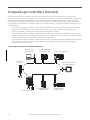
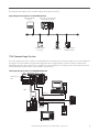
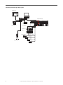
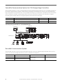
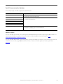
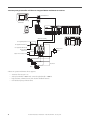
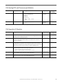
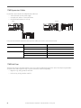
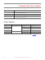
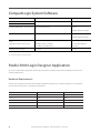
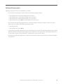
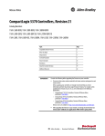
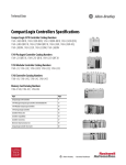
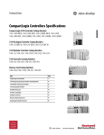
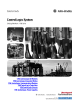
Selection Guide
CompactLogix System
Catalog Numbers 1769-L16ER-BB1B, 1769-L18ER-BB1B, 1769-L18ERM-BB1B, 1769-L24ERQB1B, 1769-L24ER-QBFC1B, 1769-L27ERM-QBFC1B, 1769-L30ER, 1769-L30ER-NSE, 1769L30ERM, 1769-L33ER, 1769-L33ERM, 1769-L36ERM, 1769-AENTR, 1768-L43, 1768-L43S,
1768-L45, 1768-L45S
1734 POINT I/O Modules
1769 Compact I/O Modules
1768 Integrated Motion Modules
1768 and 1769 Communication Modules
1768 and 1769 CompactLogix Controllers
1768 and 1769 Compact Power Supplies
CompactLogix System
Logix Controllers Comparison
Characteristic
ControlLogix
1756-71, 1756-L72, 1756L73, 1756-L73XT, 1756-L74,
1756-L75
GuardLogix
1756-L72S, 1756-L73S,
1756-L73SXT
CompactLogix
1769-L30ER, 1769-L30ERNSE, 1769-L30ERM, 1769L33ER, 1769-L33ERM,
1769-L36ERM
CompactLogix
1769-L24ER-BB1B, 1769L24ER-QBFC1B, 1769L27ERM-QBFC1B
CompactLogix
1769-L16ER-BB1B, 1769L18ER-BB1B, 1769L18ERM-BB1B
CompactLogix
1768-L43, 1768-L45
Compact GuardLogix
1768-L43S, 1768-L45S
SoftLogix 5800™
1789-L10, 1789-L30, 1789L60
Controller tasks:
• Continuous
• Periodic
• Event
32;
100 programs/task
32;
100 programs/task
32;
100 programs/task
32;
100 programs/task
• 1768-L43: 16;
32 programs/task
• 1768-L45: 30;
32 programs/task
32;
100 programs/task
Event tasks
All event triggers
All event triggers
All event triggers
All event triggers, plus
embedded inputs
All event triggers
All event triggers, plus
outbound and Windows
events
User memory
• 1756-L71: 2 MB
• 1756-L72: 4 MB
• 1756-L72S: 4 MB + 2
MB safety
• 1756-L73,
1756-L73SXT, 1756L73XT: 8 MB
• 1756-L73S: 8 MB + 4
MB safety
• 1756-L74: 16 MB
• 1756-L75: 32 MB
• 1769-L30ER, 1769L30ER-NSE, 1769L30ERM: 1MB
• 1769-L33ER, 1769L33ERM: 2 MB
• 1769-L36ERM: 3 MB
• 1769-L24ER: 750 KB
• 1769-L27ERM: 1 MB
• 1769-L16ER: 384 KB
• 1769-L18ER, 1769L18ERM: 512 KB
• 1768-L43: 2 MB
• 1768-L43S: 2 MB +
0.5 MB safety
• 1768-L45: 3 MB
• 1768-L45S: 3 MB +
1 MB safety
• 1789-L10:
2 MB; 1 controller; no
motion
• 1789-L30:
64 MB; 3 controllers
• 1789-L60:
64 MB; 6 controllers
Memory card
Secure Digital
Secure Digital
Secure Digital
Secure Digital
CompactFlash
None
Built-in ports
1 USB
2 EtherNet/IP
1 USB
2 EtherNet/IP
1 USB
2 EtherNet/IP
1 USB
1 RS-232
Depends on personal
computer
Communication options
• EtherNet/IP (standard
and safety)
• ControlNet (standard
and safety)
• DeviceNet (standard and
safety)
• DH+
• Remote I/O
• SynchLink
• Dual-port EtherNet/IP(1)
• DeviceNet
• Dual-port EtherNet/IP(1)
• DeviceNet
• Dual-port EtherNet/IP(1)
• EtherNet/IP (standard
and safety)
• ControlNet (standard
and safety)
• DeviceNet (standard)
• EtherNet/IP
• ControlNet
• DeviceNet
Controller connections
500
256
256
256
250
250
Network connections
Per module:
• 128 ControlNet (CN2/B)
• 40 ControlNet (CNB)
• 256 EtherNet/IP; 128
TCP (EN2x)
• 128 EtherNet/IP; 64 TCP
(ENBT)
• 1769-L30ER, 1769L30ER-NSE, 1769L30ERM: 256 EtherNet/
IP; 120 TCP
• 1769-L33ER, 1769L33ERM: 256 EtherNet/
IP; 120 TCP
• 1769-L36ERM:
256 EtherNet/IP;
120 TCP
• 1769-L24ER:
256 EtherNet/IP; 120
TCP
• 1769-L27ERM:
256 EtherNet/IP; 120
TCP
• 1769-L16ER:
256 EtherNet/IP;
120 TCP
• 1769-L18ER, 1769L18ERM: 256 EtherNet/
IP; 120 TCP
Per module:
• 48 ControlNet
• 128 EtherNet/IP; 64 TCP
Per module:
• 48 ControlNet
• 128 EtherNet/IP; 64 TCP
EtherNet/IP nodes in a
single Logix Designer
application, max
N/A
• 1769-L30ER, 1769L30ER-NSE, 1769L30ERM: 16
• 1769-L33ER, 1769L33ERM: 32
• 1769-L36ERM: 48
• 1769-L24ER: 8
• 1769-L27ERM: 16
• 1769-L16ER: 4
• 1769-L18ER,
1769-L18ERM: 8
N/A
N/A
Controller redundancy
Full support
Backup via DeviceNet
Backup via DeviceNet
—
Backup via DeviceNet
—
Integrated motion
• Integrated motion on an
EtherNet/IP network
• SERCOS interface
• Analog options
Integrated motion on an
EtherNet/IP network
Integrated motion on an
EtherNet/IP network
Integrated motion on an
EtherNet/IP network
SERCOS interface
• SERCOS interface
• Analog encoder input
Programming languages
• Standard task: all
languages
• Safety task: relay ladder,
safety application
instructions
•
•
•
•
•
•
•
•
•
•
•
•
• Standard task: all
languages
• Safety task: relay ladder,
safety application
instructions
•
•
•
•
•
Relay ladder
Structured text
Function block
SFC
Relay ladder
Structured text
Function block
SFC
Relay ladder
Structured text
Function block
SFC
Relay ladder
Structured text
Function block
SFC
External routines (C/
C++)
(1) CompactLogix™ 5370 controllers have two EtherNet/IP ports to connect to an EtherNet/IP network. The ports carry the same network traffic as part of the controller’s embedded switch. The controller uses only one IP address.
2
Rockwell Automation Publication 1769-SG001P-EN-P - January 2014
Select a CompactLogix System
1
CompactLogix Controllers
Select:
• A controller with sufficient memory
• A memory card
Page 7
00:00:BC:2E:69:F6
2
CompactLogix Communication
Options
Page 13
3
CompactLogix Integrated
Motion
00:00:BC:2E:69:F6
1 (Front)
2 (Rear)
Page 16
4
Compact GuardLogix
Integrated Safety
Select:
• Networks
• Communication interfaces
• Associated cables and network equipment
Select:
• A CompactLogix 5370 controller for integrated motion on an
EtherNet/IP network
• A 1768 CompactLogix controller for SERCOS motion
• Drives, motors, and accessories (use the Motion Analyzer
tool)
Select:
• A 1768 Compact GuardLogix® controller for integrated safety
Page 20
5
Additional Local I/O Modules
Select:
• 1734 POINT I/O™ or 1769 Compact I/O™ modules
• Associated cables and accessories
Page 24
6
CompactLogix Power Supplies
Page 30
Select:
• One 1769 power supply for each CompactLogix 5370 L3
controller
• One 1768 power supply for each 1768 CompactLogix
controller
• Additional 1769 power supplies as needed
Optional
Programming Software
Page 31
Rockwell Automation Publication 1769-SG001P-EN-P - January 2014
3
CompactLogix Controllers Overview
The CompactLogix system is designed to provide a Logix solution for small and mid-size applications. Typically, these
applications are machine-level control applications. A simple system can consist of a standalone controller with a single bank of
I/O modules and DeviceNet communication. In a more complex system, add other networks, motion control, and safety
control. As part of the Integrated Architecture™ system, the CompactLogix controllers use the same programming software,
network protocol, and information capabilities as all Logix controllers, providing a common development environment for all
control disciplines.
• The CompactLogix 5370 L3 controllers deliver scalable, affordable control ideal for applications from small standalone
equipment to high-performance indexing tables, process skids, case packers and erectors, and packaging. The
CompactLogix 5370 L3 controllers also provide a truly integrated motion solution.
• The CompactLogix 5370 L2 controllers combine the power of the Logix architecture with the flexibility of Compact I/O
modules. From small standalone equipment to higher performance applications, these controllers are ideal for assembly
machines, hoisting systems, process skids, indexing tables, and packaging.
• The CompactLogix 5370 L1 controllers combine the power of the Logix architecture with the flexibility of POINT I/O. Ideal
for small to mid-size machines, these controllers offer value to customers looking for the benefits of Integrated
Architecture in a lower cost system.
CompactLogix 5370 System on an EtherNet/IP Network
1769-AENTR EtherNet/IP Adapter
with 1769 Compact I/O Modules
Comm Adapter
Computer Connected via a
1783-ETAP EtherNet/IP Tap
MOD
LINK 1
NET
LINK 2
CompactLogix 5370 Controller System
X 100
X 10
LINK 2
LINK 1
X1
00:00:BC:2E:69:F6
1 (Front)
(Front)
2 (Rear)
Kinetix® 5500 Drive
with Motor
PanelView™ Plus Terminal Connected
via a 1783-ETAP EtherNet/IP Tap
U
V
W
2
1
Kinetix 6500 Drives with Motors
4
1734-AENTR POINT I/O Adapter
with POINT I/O Modules
1794-AENTR FLEX I/O Adapter
with FLEX™ I/O Modules
Rockwell Automation Publication 1769-SG001P-EN-P - January 2014
The CompactLogix 5370 L2 and L3 controllers support DeviceNet connectivity.
CompactLogix 5370 System on an DeviceNet Network
Computer with DeviceNet
Connection
CompactLogix 5370 L3 Controller System
with 1769-SDN Scanner Module
00:00:BC:2E:69:F6
1 (Front)
(Front)
2 (Rear)
Adapter
Status
DeviceNet
Status
PointBus
Status
1734-ADN
System
Power
DeviceNet
Power
1606-XLDNET DeviceNet
Power Supply
E3 Overload Relay
1734-ADN POINT I/O Adapter
with POINT I/O Modules
1768 CompactLogix System
The 1768 CompactLogix system combines a 1768 backplane for communication and motion support and a 1769 backplane for
I/O support. The 1768 controller is designed for integrated motion, integrated safety, and more complex communication
requirements than the other CompactLogix controllers. The 1768 controller has one serial port. Add 1768 modules for motion
control, EtherNet/IP communication, and ControlNet communication.
1768 CompactLogix System on an EtherNet/IP Network
1768 CompactLogix
System
SERCOS
Serial Network
EtherNet/IP Network
POINT I/O
Stratix 6000™
Kinetix 6000
PowerFlex® 70
2711P PanelView Plus
Rockwell Automation Publication 1769-SG001P-EN-P - January 2014
5
1768 Compact GuardLogix Safety System
PanelView Plus
Compact GuardLogix
CompactBlock
Guard I/O™
POINT Guard I/O™
Kinetix Servo
Drive
DANGER
Motor Feedback
7
4
1
8
5
2
DANGER
DANGER
DANGER
Motor
Power
9
6
3
0
755
PanelView Plus
6
Rockwell Automation Publication 1769-SG001P-EN-P - January 2014
CompactLogix Controllers
The CompactLogix platform brings together the benefits of the
Logix platform— common programming environment,
common networks, common control engine—in a small
footprint with high performance. Combined with Compact I/O
modules, the CompactLogix platform is perfect for tackling
smaller, machine-level control applications, with or without
simple motion, with unprecedented power and scalability. A
CompactLogix platform is ideal for systems that require
standalone and system-connected control over EtherNet/IP,
ControlNet, or DeviceNet networks.
For detailed specifications, see CompactLogix Controllers
Specifications Technical Data, publication 1769-TD005.
Characteristic
CompactLogix 5370 L1
Controllers
CompactLogix 5370 L2
Controllers
CompactLogix 5370 L3
Controllers
1768 Controllers
Controller application
Small applications
Embedded 1734 I/O modules
Small applications
Embedded 1769 I/O modules
General purpose
Integrated safety
Integrated SERCOS motion
Controller tasks
32; 100 programs/task
32; 100 programs/task
32; 100 programs/task
• 1768-L43: 16; 32 programs/task
• 1768-L45: 30; 32 programs/task
Event tasks
Consumed tag, EVENT instruction,
embedded inputs, remote I/O, axis,
and motion event triggers
Consumed tag, EVENT instruction,
remote I/O, axis, and motion event
triggers
Consumed tag, EVENT instruction,
remote I/O, axis, and motion event
triggers
Consumed tag, EVENT instruction,
remote I/O, axis, and motion event
triggers
User memory
• 1769-L16ER-BB1B: 384 KB
• 1769-L18ER-BB1B,
1769-L18ERM-BB1B: 512 KB
• 1769-L24ER-QB1B, 1769-L24ERQBFC1B: 750 KB
• 1769-L27ERM-QBFC1B: 1 MB
• 1769-L30ER, 1769-L30ERM,
1769-L30ER-NSE: 1MB
• 1769-L33ER, 1769-L33ERM: 2 MB
• 1769-L36ERM: 3 MB
•
•
•
•
Built-in ports
• 2 EtherNet/IP(1)
• 1 USB
• 2 EtherNet/IP(1)
• 1 USB
• 2 EtherNet/IP(1)
• 1 USB
• 1 port RS- 232 serial (DF1 or
ASCII)
Communication options
• Dual-port EtherNet/IP
• Dual-port EtherNet/IP
• DeviceNet
• Dual-port EtherNet/IP
• DeviceNet
• EtherNet/IP (standard and safety)
• ControlNet (standard and safety)
• DeviceNet (standard)
1768-L43: 2 MB
1768-L43S: 2 MB + 0.5 MB safety
1768-L45: 3 MB
1768-L45S: 3 MB + 1 MB safety
(1) CompactLogix 5370 controllers have two EtherNet/IP ports to connect to an EtherNet/IP network. The ports carry the same network traffic as part of the controller’s embedded switch. The controller uses only one IP address.
For information on estimating memory requirements for you application, see Logix5000 Controllers Execution Time and
Memory Use Reference Manual, publication 1756-RM087.
Rockwell Automation Publication 1769-SG001P-EN-P - January 2014
7
CompactLogix 5370 L1 Controllers
with Embedded POINT I/O Modules
The CompactLogix 5370 L1 controller comes with:
• a built-in, 24V DC nonisolated power supply.(1)
• dual EtherNet/IP ports for ring topologies.
• USB port for firmware download and programming.
• embedded digital I/O (16 DC inputs, 16 DC outputs).
Characteristic
1769-L16ER-BB1B
1769-L18ER-BB1B
1769-L18ERM-BB1B
Available user memory
384 KB
512 KB
512 KB
Memory card
• 1784-SD1 (1 GB), shipped with controller
• 1784-SD2 (2 GB)
Communication ports
• 2 EtherNet/IP
• 1 USB
Embedded I/O
• 16 sinking 24V DC digital input points
• 16 sourcing 24V DC digital output points
EtherNet/IP connections
• 256 EtherNet/IP
• 120 TCP
• 256 EtherNet/IP
• 120 TCP
• 256 EtherNet/IP
• 120 TCP
EtherNet/IP nodes in a single Logix
Designer application, max
4
8
Integrated motion on an EtherNet/IP
network
—
—
Supports up to 2 axes
Module expansion capacity
6 POINT I/O modules
8 POINT I/O modules
8 POINT I/O modules
Battery
None
Embedded power supply
10…28.8V DC
24V DC nominal
Programming software support
• RSLogix™ 5000 software, version 20 - For controllers that use firmware revision 20.xxx.
• Logix Designer application, version 21 or later - For controllers that use firmware revision 21.xxx or later.
(1) For more information on connecting a 24V DC power source to the CompactLogix 5370 L1 controller’s 24V DC nonisolated power supply, see the CompactLogix 5370 Controllers User Manual, publication 1769-UM021.
8
Rockwell Automation Publication 1769-SG001P-EN-P - January 2014
CompactLogix 5370 L2 Controllers
with Embedded Compact I/O
Modules
The CompactLogix 5370 L2 controller comes with:
• a built-in, 24V DC power supply.
• dual EtherNet/IP ports for ring topologies.
• USB port for firmware download and programming.
• a combination of embedded digital, analog, and high-speed counter I/O.
• a 1769-ECR right-end cap.
Characteristic
1769-L24ER-QB1B
1769-L24ER-QBFC1B
1769-L27ERM-QBFC1B
Available user memory
0.75 MB
0.75 MB
1 MB
Memory card
• 1784-SD1 (1 GB), shipped with controller
• 1784-SD2 (2 GB)
Communication ports
• 2 EtherNet/IP
• 1 USB
Embedded I/O
• 16 sinking/sourcing 24V DC digital input
points
• 16 sourcing 24V DC digital output points
•
•
•
•
•
EtherNet/IP connections
• 256 EtherNet/IP
• 120 TCP
• 256 EtherNet/IP
• 120 TCP
EtherNet/IP nodes in a single Logix
Designer application, max
8
Integrated motion on an EtherNet/IP
network
—
Module expansion capacity
4 1769 modules
Battery
None
Embedded power supply
24V DC
Programming software support
• RSLogix 5000 software, version 20 - For controllers that use firmware revision 20.xxx.
16 sinking/sourcing 24V DC digital input points
16 sourcing 24V DC digital output points
4 universal analog input points
2 analog output points
4 high-speed counters
• 256 EtherNet/IP
• 120 TCP
16
—
Supports up to 4 axes
• Logix Designer application, version 21 or later - For controllers that use firmware revision 21.xxx or later.
These controllers replace previous catalog numbers.
New Controller
Replaces Previous Controller(1)
Differences
1769-L24ER-QBFC1B
1769-L23-QBFC1B
1769-L23E-QBFC1B
1769-L24ER-QB1B
1769-L23E-QB1B
1769-L27ERM-QBFC1B
1769-L23E-QBFC1B
•
•
•
•
•
•
Additional memory
Integrated motion on EtherNet/IP support (1769-L27ERM-QBFC1B)
USB port instead of RS-232 port
Dual-port EtherNet/IP support
SD card support addition
Support for additional expansion I/O modules
(1) These catalog numbers are still available for sale, see page 11 for details. Please contact your local Rockwell Automation sales office for ordering information.
Rockwell Automation Publication 1769-SG001P-EN-P - January 2014
9
CompactLogix 5370 L3 Controllers
In a CompactLogix 5370 L3 controller system, the 1769 I/O modules can be placed to
the left and the right of the power supply. As many as eight modules can be placed
on each side of the power supply. The CompactLogix 5370 L3 controller comes with:
• dual EtherNet/IP ports for ring topologies.
• USB port for firmware download and programming.
Characteristic
1769-L30ER
1769-L30ERM
1769-L30ER-NSE
1769-L33ER
1769-L33ERM
1769-L36ERM
Available user memory
1 MB
1 MB
1 MB
No capacitor
2 MB
2 MB
3 MB
Memory card
1784-SD1 (1 GB), shipped with controller
1784-SD2 (2 GB)
Communication ports
• 2 EtherNet/IP
• 1 USB
EtherNet/IP connections
• 256 EtherNet/IP
• 120 TCP
• 256 EtherNet/IP
• 120 TCP
• 256 EtherNet/IP
• 120 TCP
• 256 EtherNet/IP
• 120 TCP
• 256 EtherNet/IP
• 120 TCP
EtherNet/IP nodes in a single Logix
Designer application, max
16
Integrated motion on an EtherNet/IP
network
—
Module expansion capacity
8 1769 modules
1 bank of modules
Battery
None
Power supply distance rating
4 modules
Programming software support
• RSLogix 5000 software, version 20 - For controllers that use firmware revision 20.xxx.
• 256 EtherNet/IP
• 120 TCP
32
Supports up to 4 axes
—
—
48
Supports up to 8 axes
Supports up to 16 axes
16 1769 modules
2 banks of modules
30 1769 modules
3 banks of modules
4 modules
4 modules
• Logix Designer application, version 21 or later - For controllers that use firmware revision 21.xxx or later.
These controllers replace previous catalog numbers.
New Controller(1)
Replaces Previous Controller(2)
Differences
1769-L30ER
1769-L30ERM
1769-L30ER-NSE
1769-L31
1769-L32C(3)
1769-L32E
1769-L33ER
1769-L33ERM
1769-L35CR(3)
1769-L35E
• Additional memory
• Integrated motion on EtherNet/IP support (1769-L30ERM, 1769-L33ERM,
1769-L36ERM)
• USB port instead of RS-232 port
• Dual-port EtherNet/IP support
• SD card instead of CompactFlash card
1769-L36ERM
Any previous 1769-L3x controller
(1) IMPORTANT: Typically, you can use any of the new controllers listed in each row as replacements for any of the previous controllers listed in the corresponding cell to the right. For example, you can replace a 1769-L32E with
a 1769-L30ER, 1769-L30ERM, or 1769-L30ER-NSE controller.
In some rare cases, system configuration prevents controller replacement as shown above. For example, if your system uses a 1769-L32E controller with 12 expansion modules, you cannot replace that controller with a
1769-L30ER, 1769-L30ERM, or 1769-L30ER-NSE controller. Those controllers support no more than 8 expansion modules. You must replace the 1769-L32E controller with a 1769-L33ER, 1769-L33ERM, or
1769-L36ERM controller.
We recommend that before you upgrade your controllers, consider your application requirements to verify that the replacements listed above apply.
(2) These catalog numbers are still available for sale, see page 12 for details. Please contact your local Rockwell Automation sales office for ordering information.
(3) Requires converting from ControlNet connections to EtherNet/IP connections.
10
Rockwell Automation Publication 1769-SG001P-EN-P - January 2014
1768 CompactLogix Controllers
The 1768 CompactLogix controller combines both a 1768 backplane and a 1769
backplane. The 1768 backplane supports the 1768 controller, the 1768 power supply,
and a maximum of four 1768 modules. The 1769 backplane supports 1769 modules.
Characteristic
1768-L43
1768-L43S
1768-L45
1768-L45S
Available user memory
2 MB
2 MB standard
0.5 MB safety
3 MB
3 MB standard
1 MB safety
Memory card
1784-CF128 (128 MB)
Communication options
• EtherNet/IP (standard and safety)
• ControlNet (standard and safety)
• DeviceNet (standard)
Serial communication port
1 RS-232 port
Number of 1768 modules, max
2
Number of 1769 I/O modules, max
16
30
Number of I/O banks, max
2
3
Battery
None
Programming software support
RSLogix 5000 software, version 20 or earlier
4
1769-L23x Packaged CompactLogix Controllers with
Embedded I/O
The 1769-L23x controllers provide the following functionality:
• Built-in power supply
• Either two serial ports or one serial and one EtherNet/IP port, depending on controller catalog number
• Combination of embedded digital, analog, and high-speed counter I/O modules
• 1769-ECR right-end cap
Characteristic
1769-L23-QBFC1B
1769-L23E-QB1B
1769-L23E-QBFC1B
Available user memory
512 KB
512 KB
512 KB
CompactFlash card
None
Communication ports
2 RS-232 ports (isolated DF1 or ASCII; only
nonisolated DF1)
1 EtherNet/IP port
1 RS-232 serial port (DF1 or ASCII)
1 EtherNet/IP port
1 RS-232 serial port (DF1 or ASCII)
Embedded I/O
•
•
•
•
•
• 16 DC inputs
• 16 DC outputs
•
•
•
•
•
Module expansion capacity
2 1769 modules
3 1769 modules
2 1769 modules
Embedded power supply
24V DC
Programming software support
RSLogix 5000 software, version 20 or earlier
16 DC inputs
16 DC outputs
4 analog inputs
2 analog outputs
4 high-speed counters
Rockwell Automation Publication 1769-SG001P-EN-P - January 2014
16 DC inputs
16 DC outputs
4 analog inputs
2 analog outputs
4 high-speed counters
11
1769-L3x Modular CompactLogix Controllers
In a 1769-L3x controller system, the 1769 I/O modules can be placed to the left and the right of the power supply. As many as
eight modules can be placed on each side of the power supply.
Characteristic
1769-L31
1769-L32C
1769-L32E
1769-L35CR
1769-L35E
Available user memory
512 KB
750 KB
750 KB
1.5 MB
1.5 MB
CompactFlash card
1784-CF128
Communication ports
2 RS-232 ports (isolated
DF1 or ASCII; only
nonisolated DF1)
1 ControlNet port
1 RS-232 port (DF1 or
ASCII)
1 EtherNet/IP port
1 RS-232 port (DF1 or
ASCII)
1 ControlNet port
1 RS-232 port (DF1 or
ASCII)
1 EtherNet/IP port
1 RS-232 port (DF1 or
ASCII)
Module expansion capacity
16 1769 modules
30 1769 modules
Power supply distance rating
4 modules
Programming software support
RSLogix 5000 software, version 20 or earlier
Controller Memory Use
These equations provide an estimate of the memory needed for a CompactLogix controller. These numbers are
rough estimates.
Controller tasks
_____ * 4000
=
_____ bytes (minimum 1 task)
Digital I/O points
_____ * 400
=
_____ bytes
Analog I/O points
_____ * 2600
=
_____ bytes
DeviceNet modules(1)
_____ * 7400
=
_____ bytes
Other communication modules(2)
_____ * 2000
=
_____ bytes
Motion axes
_____ * 8000
=
_____ bytes
FactoryTalk® alarm instruction
_____ * 1000
=
_____ bytes (per alarm)
FactoryTalk subscriber
_____ * 10000
=
_____ bytes
(1) The first DeviceNet module is 7400 bytes. Additional DeviceNet modules are 5800 bytes each.
(2) Count all the communication modules in the system, not just those in the local chassis. This includes device connection modules, adapter modules, and ports on PanelView
terminals.
Reserve 20…30% of the controller memory for future expansion.
12
Rockwell Automation Publication 1769-SG001P-EN-P - January 2014
CompactLogix Communication Options
You can configure your system for information exchange between a range of devices and computing platforms and operating
systems. Select a CompactLogix controller with integrated communication or the appropriate communication module.
For detailed specifications, see:
• CompactLogix Controllers Specifications Technical Data, publication 1769-TD005.
• CompactLogix Communication Modules Specifications Technical Data, publication 1769-TD007.
EtherNet/IP Communication Options
The Ethernet Industrial network protocol (EtherNet/IP) is an open industrial-networking standard that supports both real-time
I/O messaging and message exchange. The EtherNet/IP network uses off-the-shelf Ethernet communication chips and physical
media.
Dual-port EtherNet/IP support embeds switch technology directly in the controller to so the controller can operate on star,
linear, or ring EtherNet/IP topologies.
Cat. No.
Description
Communication Rate
Logix Resources(1)
TCP/IP Connections
1769-L16ER-BB1B,
CompactLogix 5370 L1 controller with integrated EtherNet/IP dualport, POINT I/O form factor
10/100 Mbps
4 nodes
256 EtherNet/IP connections
120
1769-L18ER-BB1B, 1769L18ERM-BB1B
1769-L24ER-BB1B, 1769L24ER-QBFC1B
8 nodes
256 EtherNet/IP connections
CompactLogix 5370 L2 controller with integrated EtherNet/IP dualport, Compact I/O form factor
10/100 Mbps
8 nodes
256 EtherNet/IP connections
10/100 Mbps
16 nodes
256 EtherNet/IP connections
CompactLogix 5370 L3 controller with integrated EtherNet/IP dual-port 10/100 Mbps
16 nodes
256 EtherNet/IP connections
1769-L27ERM-QBFC1B
1769-L30ER, 1769-L30ERM
1769-L33ER, 1769-L33ERM
32 nodes
256 EtherNet/IP connections
1769-L36ERM
48 nodes
256 EtherNet/IP connections
120
120
1769-AENTR
1769 EtherNet/IP adapter
10/100 Mbps
128 EtherNet/IP connections
96
1768-ENBT
1768 EtherNet/IP communication bridge module
10/100 Mbps
128 EtherNet/IP connections
64
1768-EWEB
1768 Ethernet web server module
10/100 Mbps
128 EtherNet/IP connections
64
(1) The number of nodes listed for CompactLogix 5370 controllers represents the maximum number of EtherNet/IP nodes you can include in a Logix Designer application project for those controller. For example, in a Logix
Designer application project that uses a 1769-L18ERM-BB1B controller, you can add as many as 8 EtherNet/IP nodes to the project.
Rockwell Automation Publication 1769-SG001P-EN-P - January 2014
13
ControlNet Communication Options for 1768 CompactLogix Controllers
The ControlNet network is an open, control network for real-time, high-throughput applications. The ControlNet network uses
the Common Industrial Protocol (CIP) to combine the functionality of an I/O network and a peer-to-peer network providing
high-speed performance for both functions. The ControlNet network gives you deterministic, repeatable transfers of all missioncritical control data in addition to supporting transfers of non-time-critical data. I/O updates and controller-to-controller
interlocking always take precedence over program uploads and downloads and messaging.
Cat. No.
Description
Communication Rate
Logix Connections
1768-CNB
1768 CompactLogix controller, ControlNet communication bridge module, single media
5 Mbps
48
1768-CNBR
1768 CompactLogix controller, ControlNet communication bridge module, redundant media
10/100 Mbps
48
1768 CompactLogix Controllers on a ControlNet Network
ControlLogix®
PanelView Plus
ControlNet Network
1768 CompactLogix
FLEX I/O
PowerFlex 4
PowerFlex 7
POINT I/O
DeviceNet Communication Options
The DeviceNet network is an open, low-level network that provides connections between simple industrial devices (such as
sensors and actuators) and higher-level devices (such as controllers and computers).
Cat. No.
Description
Communication Rate
Number of Nodes
1769-SDN
Compact I/O DeviceNet scanner module
64
1769-ADN
Compact I/O DeviceNet adapter module
125 Kbps (500 m max)
250 Kbps (250 m max)
500 Kbps (100 m max)
14
Rockwell Automation Publication 1769-SG001P-EN-P - January 2014
Serial Communication Options
These CompactLogix controllers support serial communication.
Cat. No.
Serial Options
1769-L16ER-BB1B, 1769-L18ER-BB1B, 1769-L18ERM-BB1B
1734-232ASC module for an RS-232 serial interface
1734-485 ASC module for an RS-422 and RS-485 serial device
1769-L24ER-BB1B, 1769-L24ER-QBFC1B
1769-ASCII module for an ASCII interface to RS-232, RS-422, and RS-485 devices
1769-SM2 module for a Modbus RTU interface
1769-L27ERM-QBFC1B
1769-L30ER, 1769-L30ERM
1769-L33ER, 1769-L33ERM
1769-L36ERM
1768-L43, 1768-L43S, 1768-L45, 1768-L45S
Built-in serial port
1769-ASCII module for an ASCII interface to RS-232, RS-422, and RS-485 devices
1769-SM2 module for a Modbus RTU interface
Modbus Support
To access a Modbus TCP network, connect through the embedded Ethernet port of the CompactLogix 5370 controllers and
execute a specific ladder-logic routine. For more information, see Knowledgebase document 470365 at http://
www.rockwellautomation.com/knowledgebase/.
To access a Modbus RTU network, connect through the serial port (if available) and execute a specific ladder-logic routine. For
more information, see Using Logix5000 Controllers as Masters or Slaves on Modbus Application Solution, publication
CIG-AP129.
Rockwell Automation Publication 1769-SG001P-EN-P - January 2014
15
CompactLogix Integrated Motion
The Logix architecture supports motion control components that work in a wide variety of machine architectures.
• Integrated motion on EtherNet/IP supports a connection to Ethernet drives.
• The Kinetix integrated-motion solution uses a SERCOS interface module to perform multi-axis, synchronized motion.
• Logix integrated motion supports the analog family of servo modules for controlling drives/actuators.
• Networked motion provides the ability to connect via the DeviceNet network to a single axis drive to perform point-topoint indexing.
Motion Feature
CompactLogix 5370 L3
CompactLogix 5370 L2
CompactLogix 5370 L1
1768-L43, 1768-L43S
CompactLogix and
Compact GuardLogix
1768-L45, 1768-L45S
CompactLogix and
Compact GuardLogix
EtherNet/IP sequence of events for software
registration
Yes
Yes
Yes
Yes
Yes
Kinematics
Yes
Yes
Yes
No
No
Yes(2)
Yes(3)
No
No
(1)
Integrated motion on an EtherNet/IP network
Yes
Indexing
Yes with AMCI 1769-3602 Yes with AMCI 1769-3602 Yes with one of these
pulse-train output module pulse-train output module pulse-train output
modules:
• AMCI 1734-3401
• AMCI 1734-3401L
—
—
Load observer (with only Kinetix 6500 drives)
Yes
Yes
Yes
No
No
Total axis count
100
100
100
12
• 4 position
• 2 feedback
• 6 virtual
16
• 8 position
• 2 feedback
• 6 virtual
Virtual axis, max.
100
100
100
6
6
EtherNet/IP axis, max.
16
4
2
None
None
EtherNet/IP feedback, VHz, torque, or velocity
axis, max.
48
16
8
None
None
(1) In the CompactLogix 5370 L3 controller family, only the 1769-L30ERM, 1769-L33ERM, 1769-L36ERM controllers support Integrated Motion on an EtherNet/IP network.
(2) In the CompactLogix 5370 L2 controller family, only the 1769-L27ERM-QBFC1B controller supports Integrated Motion on an EtherNet/IP network.
(3) In the CompactLogix 5370 L1 controller family, only the 1769-L18ERM-BB1B controller supports Integrated Motion on an EtherNet/IP network.
For more information, see the:
• Motion Analyzer CD to size your motion application and to make final component selection. Download the software
from http://www.ab.com/motion/software/analyzer.html.
• Kinetix Motion Control Selection Guide, publication GMC-SG001, to verify drive, motor, and accessory specifications.
16
Rockwell Automation Publication 1769-SG001P-EN-P - January 2014
Some CompactLogix 5370 controllers support integrated motion on an EtherNet/IP network. Select the controller with
sufficient axis-support for your application.
Integrated Motion on an EtherNet/IP Network Example Configuration
Computer
CompactLogix 5370 Controller System
00:00:BC:2E:69:F6
1 (Front)
2 (Rear)
Stratix 8000™ Switch
PanelView Plus Terminal
PowerFlex 40 Drive
00
300
Kinetix 350 Single-axis Drive
00
300
Kinetix 350 Single-axis Drive
SERCOS Interface Modules
The 1768 CompactLogix controller supports a SERCOS interface.
Cat. No.
Description
Number of Axis
1768-M04SE
1768 CompactLogix SERCOS interface modules
4
The SERCOS interface module can connect to these servo drives:
• 2093 Kinetix 2000 servo drive
• 2094 Kinetix 6000 servo drive
• 2094 Kinetix 6000M integrated drive-motor system
• 2099 Kinetix 7000 high-power servo drive
• 2098 Ultra™ 3000 SERCOS servo drive
• 1394C SERCOS drive
• 8720MC spindle
For detailed SERCOS specifications, see CompactLogix Integrated Motion Specifications Technical Data,
publication 1768-TD001.
With this controller
You can have
1768-L43
• Four axis
• Two feedback axis
• Six virtual axis
1768-L45
• Eight axis
• Four feedback axis
• Six virtual axis
Rockwell Automation Publication 1769-SG001P-EN-P - January 2014
17
1768 CompactLogix Controller and Three-axis Integrated Motion with Kinetix Servo Drives
EtherNet/IP Network
PanelView Plus
PowerFlex 4
POINT I/O
SERCOS Fiber-optic Ring
User-supplied Input Power
User-supplied Control Contractor
User-supplied Circuit Breaker and
Contractor Monitor
I/O Connections
To Control
String
Auxiliary Encoder
Feedback
Integrated
Axis Module
To Input Sensors and Control String
Motor Feedback
Motor Power
Motor
A three-axis system with Kinetix drives supports:
• execution of 4 axes per 1 ms.
• velocity bandwidth > 400 Hz and current loop bandwidth > 1000 Hz.
• high resolution, unlimited travel, and absolute feedback features.
• two feedback ports per Kinetix drive.
18
Rockwell Automation Publication 1769-SG001P-EN-P - January 2014
1768 CompactLogix Controller and Four-axis Integrated Motion with Kinetix Drives and LIM Interface
PanelView Plus
Plant MRP System Database, Order
Tracking System
EtherNet/IP Network
Stratix
PowerFlex 4
PowerFlex 7
Three-phase Input
Power
POINT I/O
SERCOS Fiber-optic Ring
Line Interface
Module
Auxiliary Encoder
Feedback
I/O Connections
Motor Power
Motor
Motor Feedback
PowerFlex 4
PowerFlex 7
1606
Power
Supply
E3 Overload POINT I/O Weigh
Relay
Scale
A four-axis system with Kinetix drives supports:
• execution of 4 axes per 1 ms.
• velocity bandwidth > 400 Hz and current loop bandwidth > 1000 Hz.
• high resolution, unlimited travel, and absolute feedback features.
• two feedback ports per Kinetix drive.
• optional 2094 Line Interface Module (LIM) as the incoming power source for an entire control panel.
Rockwell Automation Publication 1769-SG001P-EN-P - January 2014
19
Compact GuardLogix Integrated Safety
The Compact GuardLogix controller is a 1768-L4xS CompactLogix controller that provides safety control to achieve SIL 3/PLe
according to ISO 13849. A major benefit of this system is that it’s still a single project, safety and standard together.
Application
Description
SIL 1, 2, 3
The Compact GuardLogix controller system is type-approved and certified for use in safety applications up to and including SIL 3 according to IEC 61508, and
applications up to and including PLe/Cat.4 according to ISO 13849-1. For more information, see:
• GuardLogix Controllers Systems Safety Reference Manual, publication 1756-RM093.
• Compact GuardLogix Controllers User Manual, publication 1768-UM002.
• GuardLogix Safety Application Instruction Set Reference Manual, publication 1756-RM095.
During development, safety and standard have the same rules, multiple programmers, online editing, and forcing are all
possible. Once the project is tested and ready for final validation, you apply the safety application signature and safety-lock the
application to set the safety task to a SIL 3 integrity level, which is then enforced by the GuardLogix® controller. When safety
memory is locked and protected, the safety logic can't be modified and all safety functions operate with SIL 3 integrity. On the
standard side of the GuardLogix controller, all functions operate like a regular Logix controller. Thus online editing, forcing, and
other activities are all possible.
With this level of integration, safety memory can be read by standard logic and external devices, like HMIs or other controllers,
eliminating the need to condition safety memory for use elsewhere. The result is easy system-wide integration and the ability to
display safety status on displays or marquees. Use Guard I/O modules for field device connectivity. For safety interlocking
between GuardLogix controllers use Ethernet or ControlNet networks. Multiple GuardLogix controllers can share safety data for
zone to zone interlocking, or a single GuardLogix controller can use remote distributed safety I/O between different cells/areas.
In addition to the standard features of a CompactLogix controller, the Compact GuardLogix controller has these safety-related
features.
Characteristic
1768-L43S
1768-L45S
Available user memory
2 MB standard
0.5 MB safety
3 MB standard
1 MB safety
Communication options
• EtherNet/IP (standard and safety)
• ControlNet (standard and safety)
• DeviceNet (standard)
• EtherNet/IP (standard and safety)
• ControlNet (standard and safety)
• DeviceNet (standard)
Programming languages
• Standard task: all languages
• Safety task: relay ladder, safety application instructions
• Standard task: all languages
• Safety task: relay ladder, safety application instructions
20
Rockwell Automation Publication 1769-SG001P-EN-P - January 2014
Additional Local I/O Modules
1734 POINT I/O Modules
Additional 1734 POINT I/O modules can be installed
on a CompactLogix 5370 L1 controller. The POINT I/O
family is ideal for applications where flexibility and
low-cost of ownership are key for successful control
system design and operation.
The base (A) mounts onto the DIN rail and provides
the backplane. The POINT I/O module (B) snaps into
the base. The removable terminal block (C) also
snaps into the base and provides the wiring and
terminations for field-side connections, as well as
system power for the backplane.
B
B
A
A
C
1734 AC Digital Modules
Cat. No.
Inputs/Outputs
Voltage Category
Wiring Base
POINTBus™ Current @
5V DC
1734-IA2
2 inputs, nonisolated, sink
120V AC
1734-TB, 1734-TBS, 1734-TOP, 1734-TOPS
75 mA
1734-IA4
4 inputs, nonisolated, sink
1734-IM2
2 inputs, nonisolated, sink
220V AC
1734-TB, 1734-TBS, 1734-TOP, 1734-TOPS
75 mA
1734-IM4
4 inputs, nonisolated, sink
1734-OA2
2 outputs, nonisolated, source
120/220V AC
1734-TB, 1734-TBS, 1734-TOP, 1734-TOPS
75 mA
1734-OA4
4 outputs, nonisolated, source
Rockwell Automation Publication 1769-SG001P-EN-P - January 2014
21
1734 DC Digital Modules
Cat. No.
Inputs/Outputs
Voltage Category
Wiring Base
POINTBus Current @
5V DC
1743-IB2
2 inputs, sink
24V DC
1734-TB, 1734-TBS
75 mA
1734-IB4
4 inputs, sink
1734-IB4D
4 inputs, sink, diagnostic
24V DC
1734-TB, 1734-TBS, 1734-TOP, 1734-TOPS
50 mA
1734-IB8
8 inputs, sink
24V DC
1734-TB, 1734-TBS
75 mA
1734-IB8S
8 inputs, sink, safety
24V DC
1734-TB,1734-TOP
175 mA
1734-IV2
2 inputs, source
24V DC
1734-TB,1734-TBS
75 mA
1734-IV4
4 inputs, source
1734-IV8
8 inputs, source
1734-OB2
2 outputs, nonisolated, source
12/24V DC
1734-TB, 1734-TBS
75 mA
1734-OB2E
2 outputs, nonisolated protected, source
1734-OB4
4 outputs, nonisolated, source
1734-OB4E
4 outputs, nonisolated protected, source
1734-OB8
8 outputs, nonisolated, source
1734-OB8E
8 outputs, nonisolated protected, source
1734-OB8S
8 outputs, safety
24V DC
1734-TB,1734-TOP
190 mA
1734-OV2E
2 outputs, nonisolated protected, sink
12/24V DC
1734-TB, 1734-TBS
75 mA
1734-OV4E
4 outputs, nonisolated protected, sink
1734-OV8E
8 outputs, nonisolated protected, sink
1734 Relay Contact Output Modules
Cat. No.
Inputs/Outputs
Voltage Range
Wiring Base
POINTBus Current @
5V DC
1734-OW2
2 Form A (normally open) relays
1734-TB,1734-TBS
80 mA
1734-OW4
4 Form A (normally open) relays
1734-OX2
2 Form C isolated (normally open; normally closed)
electromechanical relays
5…28.8V DC @ 2.0 A
48V DC @ 0.5 A
125V DC @ 0.25 A
125V DC @ 2.0 A
240V AC @ 2.0 A
100 mA
1734 Analog and Temperature Modules
Cat. No.
Inputs/Outputs
Range
Resolution
Wiring Base
POINTBus Current @
5V DC
1734-IE2C
2 single-ended, nonisolated,
current
4…20 mA
0…20 mA
16 bits over 0…21 mA
0.32 μA/cnt
1734-TB, 1734-TBS
75 mA
1734-IE2V
2 single-ended, nonisolated,
voltage
0…10V (-0.0V under, +0.5V
over)
±10V (-0.5V under, +0.5V over)
15 bits plus sign
320 μV/cnt in unipolar or bipolar
mode
1734-IE4C
4 single-ended, nonisolated,
current
4…20 mA
0…20 mA
16 bits - over 0…21 mA
0.32 μA/cnt
22
Rockwell Automation Publication 1769-SG001P-EN-P - January 2014
Cat. No.
Inputs/Outputs
Range
Resolution
Wiring Base
POINTBus Current @
5V DC
1734-IE4S
4 inputs, single-ended,
safety rated
0…20 mA, 4…20 mA
±5V, 0…5V, ±10V, 0…10V
12 bits
1734-TB, 1734-TBS,
1734-TOP, 1734-TOPS,
1734-TOP3, 1734-TOP3S
110 mA
1734-IE8C
8 single-ended, nonisolated,
current
4…20 mA
0…20 mA
16 bits - over 0…21 mA
0.32 μA/cnt
1734-TB, 1734-TBS
75 mA
1734-IR2
2 single-ended, nonisolated
0…600 Ω
16 bits
9.5 mΩ/cnt
0.03 °C/cnt (Pt385 @ 25 °C)
[0.05 °F/cnt (Pt385 @ 77 °F)]
1734-TB, 1734-TBS,
1734-TOP, 1734-TOPS
220 mA
1734-IR2E
2 single-ended, nonisolated,
protected
0…220 Ω
16 bits
2.4 mΩ/cnt
0.006 °C/cnt (Pt385 @ 25 °C)
[0.0114 °F/cnt (Pt385 @ 77 °F)]
1734-IT2I
2 differential, individually isolated Sensors B, C, E, J, K, N, R, S, T
15 bits plus sign
2.5 μV/cnt
1734-TBCJC
175 mA
1734-OE2C
2 single-ended, nonisolated,
current
4…20 mA
0…20 mA
13 bits over 0…21mA
2.5 μA/cnt (average)
3…2.7 μA/cnt (typical range)
1734-TB, 1734-TBS,
1734-TB3, 1734-TB3S
75 mA
1734-OE2V
2 single-ended, nonisolated,
voltage
0…10V (-0.0V under, +0.5V
over)
±10V (-0.5V under, +0.5V over)
14 bits (13 plus sign)
1.28 mV/cnt in unipolar or
bipolar mode
1734-OE4C
4 single-ended, nonisolated,
current
4…20 mA
0…20 mA
16 bits over 0…21 mA
0.32 μA/cnt)
1734 Counter Modules
Cat. No.
Inputs/Outputs
Range
Frequency
Wiring Base
POINTBus Current @
5V DC
1734-IJ
1 - 1 group of A/Areturn, B/
Breturn and Z/Zreturn
5V DC
1734-TB, 1734-TBS,
1734-TB3, 1734-TB3S
160 mA
1734-IK
1 - 1 group of A/Areturn, B/
Breturn and Z/Zreturn
15…24V DC
1.0 MHz counter and encoder X1
500 kHz encoder X2 (no filter
250 kHz encoder X4 (no filter)
1734-VHSC24
1 - 1 group of A/Areturn, B/
Breturn and Z/Zreturn
15…24V DC
180 mA
1734-VHSC5
1 - 1 group of A/Areturn, B/
Breturn and Z/Zreturn
5V DC
180 mA
160 mA
1734 Self-configurable Modules
Cat. No.
Inputs/Outputs
Voltage Category
Wiring Base
POINTBus Current @
5V DC
1734-8CFG
8 self configurable
24V DC
1734-TB, 1734-TBS, 1734-TOP, 1734-TOPS
100 mA
Rockwell Automation Publication 1769-SG001P-EN-P - January 2014
23
1734 Specialty I/O Modules
Cat. No.
Description
Wiring Base
POINTBus Current
1734-232ASC
The 1734-232ASC and 1734-485ASC serial interface modules offer a serial-link communication interface
solution for peripheral products with RS-232 (only 1734-232ASC), RS-485, and RS-422 ports (only
1734-485ASC.)
1734-TB, 1734-TBS
75 mA
1734-ARM
The 1734-ARM address reserve module reserves address and slot numbers to maintain a numbering scheme of
an existing system. The 1734-ARM has no module configuration and does not communicate I/O data.
1734-TB, 1734-TBS
75 mA
1734-CTM
The common terminal module (1734-CTM) and voltage term66inal module (1734-VTM) expand the
termination capabilities of POINT I/O modules. Install the modules to provide support for higher density (8
channel) POINT I/O modules.
1734-TB, 1734-TBS,
1734-TOP, 1734-TOPS
75 mA
The 1734-SSI module collects serial data from absolute-position, encoding sensors that use standard
Synchronous Serial Interface (SSI) protocol.
1734-TB, 1734-TBS
110 mA
1734-485ASC
1734-VTM
1734-SSI
1769 Compact I/O Modules
The 1769 Compact I/O modules can be installed on the
CompactLogix 5370 L2 and L3 controllers and 1768
CompactLogix controllers. The modules mechanically
lock together by means of a tongue-and-groove design
and have an integrated communication bus that is
connected from module to module by a moveable bus
connector.
Each I/O module includes a built-in removable terminal
block with finger-safe cover for connections to I/O
sensors and actuators. The terminal block is behind a
door at the front of the module. I/O wiring can be routed
from beneath the module to the I/O terminals.
C
A
D
B
F
E
B
For detailed specifications, see 1769 Compact I/O Modules Specifications Technical Data, publication 1769-TD006.
Power Supply Distance Ratings
Check each module’s specification table for the power supply distance rating. This indicates how many slot positions the
module can be from the power supply.
24
Rockwell Automation Publication 1769-SG001P-EN-P - January 2014
1769 AC Digital Modules
Cat. No.
Inputs/Outputs
Voltage Category
Operating Voltage Range
Backplane Current
Power Supply
Distance Rating
1769-IA8I
8 inputs, individually
isolated
100/120V AC
79…132V AC,
47…63 Hz
90 mA @ 5.1V(1)
8
1769-IA16
16 inputs
100/120V AC
79…132V AC,
47…63 Hz
115 mA @ 5.1V
8
1769-IM12
12 inputs
200/240V AC
159…265V AC,
47…63 Hz
100 mA @ 5.1V
8
1769-OA8
8 outputs
100/240V AC
85…265V AC
47…63 Hz
145 mA @ 5.1V
8
1769-OA16
16 outputs
100/240V AC
85…265V AC
47…63 Hz
225 mA @ 5.1V
8
Voltage Category
Operating Voltage Range
Backplane Current
Power Supply
Distance Rating
(1) Maximum is 190 mA.
1769 DC Digital Modules
Cat. No.
Inputs/Outputs
1769-IG16
16 inputs
5V DC TTL
4.5…5.5V DC
120 mA @ 5.1V
8
1769-IQ16
16 inputs
24V DC sink/source
10…30V DC @ 30 °C (86 °F)
10…26.4V DC @ 60 °C (140 °F)
115 mA @ 5.1V
8
1769-IQ16F
16 inputs, high-speed
24V DC sink/source
10…30V DC @ 30 °C (86 °F)
10…26.4V DC @ 60 °C (140 °F)
100 mA @ 5.1V
8
1769-IQ32
32 inputs
24V DC sink/source
10…30V DC @ 30 °C (86 °F)
10…26.4V DC @ 60 °C (140 °F)
170 mA @ 5.1V
8
1769-IQ32T
32 inputs
24V DC sink/source
20.4…26.4V DC @ 60 °C
(140 °F)
170 mA @ 5.1V
8
1769-IQ6XOW4
6 inputs
4 outputs
24V DC sink/source input
AC/DC normally open relay
contact outputs
10…30V DC @ 30 °C (86 °F)
10…26.4V DC @ 60 °C (140 °F)
105 mA @ 5.1V
50 mA @ 24V
8
1769-OB8
8 outputs
24V DC source
20.4…26.4V DC
145 mA @ 5.1V
8
1769-OB16
16 outputs
24V DC source
20.4…26.4V DC
200 mA @ 5.1V
8
1769-OB16P
16 outputs, protected
24V DC source
20.4…26.4V DC
160 mA @ 5.1V
8
1769-OB32
32 outputs
24V DC source
20.4…26.4V DC
300 mA @ 5.1V
6
1769-OB32T
32 outputs
24V DC source
10.2…26.4V DC
220 mA @ 5.1V
8
1769-OG16
16 outputs
5V DC TTL
4.5…5.5V DC
200 mA @ 5.1V
8
1769-OV16
16 outputs
24V DC sink
20.4…26.4V DC
200 mA @ 5.1V
8
1769-OV32T
32 outputs
24V DC sink
10.2…26.4V DC
300 mA @ 5.1V
8
Rockwell Automation Publication 1769-SG001P-EN-P - January 2014
25
1769 Contact Output Modules
Cat. No.
Inputs/Outputs
Operating Voltage Range
Backplane Current
Power Supply
Distance Rating
1769-OW8
8 outputs
5…265V AC
5…125V DC
125 mA @ 5.1V
100 mA @ 24V
8
1769-OW8I
8 outputs, individually isolated
5…265V AC
5…125V DC
125 mA @ 5.1V
100 mA @ 24V
8
1769-OW16
16 outputs
5…265V AC
5…125V DC
205 mA @ 5.1V
180 mA @ 24V
8
1769 Analog Modules
Cat. No.
Inputs/Outputs
Range
Resolution
Backplane Current
Power Supply
Distance Rating
1769-IF4
4 inputs, differential or singleended
±10V, 0…10V, 0…5V, 1…5V
0…20 mA, 4…20 mA
14 bits (unipolar)
14 bits plus sign (bipolar)
120 mA @ 5.1V
60 mA @ 24V
8
1769-IF4I
4 inputs, differential or singleended, individually isolated
±10V, 0…10V, 0…5V, 1…5V
0…20 mA, 4…20 mA
16 bits (unipolar)
15 bits plus sign (bipolar)
145 mA @ 5.1V
125 mA @ 24V
8
1769-IF8
8 inputs, differential or singleended
±10V, 0…10V, 0…5V, 1…5V
0…20 mA, 4…20 mA
16 bits (unipolar)
15 bits plus sign (bipolar)
120 mA @ 5.1V
70 mA @ 24V
8
1769-IF16C
16 inputs, single-ended
0…20 mA, 4…20 mA
16 bits (unipolar)
15 bits plus sign (bipolar)
190 mA @ 5.1V
70 mA @ 24V
8
1769-IF16V
16 inputs, differential
±10V, 0…10V, 0…5V, 1…5V
16 bits (unipolar)
15 bits plus sign (bipolar)
190 mA @ 5.1V
70 mA @ 24V
8
1769-IF4XOF2
4 differential or single-ended
inputs
2 single-ended outputs
0…10V
0…20 mA
Input: 8 bits plus sign
Output: 8 bits plus sign
120 mA @ 5.1V
160 mA @ 24V
8
1769-IF4FXOF2F
4 fast differential or single-ended
inputs
2 fast single-ended outputs
±10V, 0…10V, 0…5V, 1…5V
0…20 mA, 4…20 mA
Input: 14 bits (unipolar)
14 bits plus sign (bipolar)
Output: 13 bits (unipolar)
13 bits plus sign (bipolar)
220 mA @ 5.1V
120 mA @ 24V
8
1769-OF2
2 outputs, single-ended
±10V, 0…10V, 0…5V, 1…5V
0…20 mA, 4…20 mA
14 bits (unipolar)
14 bits plus sign (bipolar)
120 mA @ 5.1V
120 mA @ 24V
8
1769-OF4
4 outputs, single-ended
±10V, 0…10V, 0…5V, 1…5V
0…20 mA, 4…20 mA
15 bits plus sign unipolar and
bipolar
120 mA @ 5.1V
170 mA @ 24V
8
1769-OF4CI
4 outputs, differential, individually
isolated
0…20 mA
4…20 mA
16 bits (unipolar)
140 mA @ 5.1V
145 mA @ 24V
8
1769-OF4VI
4 outputs, differential, individually
isolated
±10V
0…10V
0…5V
1…5V
15 bits plus sign (bipolar)
145 mA @ 5.1V
75 mA @ 24V
8
1769-OF8C
8 outputs, single-ended
0…20 mA
4…20 mA
16 bits (unipolar)
140 mA @ 5.1V
145 mA @ 24V
8
1769-OF8V
8 outputs, single-ended
±10V
0…10V
0…5V
1…5V
16 bits plus sign (bipolar)
145 mA @ 5.1V
125 mA @ 24V
8
26
Rockwell Automation Publication 1769-SG001P-EN-P - January 2014
1769 Analog RTD and Thermocouple Modules
Cat. No.
Inputs/Outputs
Sensors Supported
Backplane Current
Power Supply
Distance Rating
1769-IR6
6 RTD inputs
100, 200, 500, 1000 Ω Platinum 385
100, 200, 500, 1000 Ω Platinum 3916
120 Ω Nickel 618
120 Ω Nickel 672
10 Ω Nickel-iron 518
0…150 Ω, 0…500 Ω, 0…1000 Ω,
0…3000 Ω
100 mA @ 5.1V
45 mA @ 24V
8
1769-IT6
6 thermocouple inputs
Thermocouple types B, C, E, J, K, N, R, S, T
±50V, ±100V
100 mA @ 5.1V
45 mA @ 24V
8(1)
(1) To reduce the effects of electrical noise, install the 1769-IT6 module at least two slots away from the AC power supplies.
1769 Specialty I/O Modules
Cat. No.
Description
Backplane Current
Power Supply
Distance Rating
1769-ARM
Use a 1769-ARM address reserve module to reserve module slots. After creating an I/O configuration and user
program, you can remove and replace any I/O module in the system with a 1769-ARM module once you inhibit
the removed module in the Logix Designer application.
60 mA @ 5.1V
8
1769-ASCII
The 1769-ASCII module, a general purpose two-channel ASCII interface, provides a flexible network interface to
a wide variety of RS-232, RS-485, and RS-422 ASCII devices. The module provides the communication
connections to the ASCII device.
425 mA @ 5.1V
4
1769-BOOLEAN
Use the 1769-BOOLEAN module in applications that require repeatability, such as material handling and
packaging, when there is a requirement to activate an output based on an input’s transition. If the Boolean
expression is true, the output is directed to the ON state. If the Boolean expression is false, the output channel is
directed to the OFF state. There are four operators that you can configure as OR, AND, XOR, or none.
220 mA @ 5.1V
8
1769-HSC
Use the 1769-HSC when you need:
• a counter module that is capable of reacting to high-speed input signals.
• to generate rate and time-between-pulses (pulse interval) data.
• as many as two channels of quadrature or four channels of pulse/count inputs.
245 mA @ 5.1V
4
1769-SM1
The Compact I/O to DPI/SCANport™ module connects to PowerFlex 7-class drives, other DPI-based host
devices, and SCANport-based host devices such as 1305 and 1336 PLUS II drives.
280 mA @ 5.1V
6
1769-SM2
The Compact I/O to DSI/Modbus module connects to PowerFlex 4-class drives and to other Modbus RTU slave
devices, such as PowerFlex 7-class drives with 20-COMM-H RS485 HVAC adapters.
350 mA @ 5.1V
4
Rockwell Automation Publication 1769-SG001P-EN-P - January 2014
27
1769 Expansion Cables
If you divide 1769 modules into multiple banks, make sure:
• each bank needs its own power supply.
• use expansion cables to connect the banks.
• the last I/O bank requires an end cap.
Vertical
Horizontal
How you orient I/O banks determines the expansion cables you need to connect the I/O banks.
If you add a
And connect the chassis
Use this cable(1)
Second bank
Right to left
1769-CRLx
Right to right
1769-CRRx
Right to left
1769-CRLx
Right to right
1769-CRRx
Left to left
1769-CLLx
Third bank
(1) Where x = 1 for 1 ft (305 mm) or 3 for 3.28 ft (1 m).
1769 End Caps
The final 1769 Compact I/O bank requires an end cap on the end without the expansion cable. The CompactLogix 5370 L2
controller comes with a right-end cap, so you do not need to order one separately.
• Right end cap, catalog number 1769-ECR
• Left end cap, catalog number 1769-ECL
28
Rockwell Automation Publication 1769-SG001P-EN-P - January 2014
1769 Wiring Systems
As an alternative to buying removable terminal blocks (RTBs) and connecting the wires yourself, you can buy a wiring system of:
• interface modules (IFMs) that provide the output terminal blocks for digital I/O modules. Use the pre-wired cables that
match the I/O module to the IFM.
• analog interface modules (AIFMs) that provide the output terminal blocks for analog I/O modules. Use the pre-wired
cables that match the I/O module to the AIFM.
• I/O module-ready cables. One end of the cable assembly is an RTB that plugs into the front of the I/O module. The other
end has individually color-coded conductors that connect to a standard terminal block.
Removable Terminal Kits
You can order removable terminal kits with the CompactLogix 5370 L1 and L2 controllers separately. The kits are used to
connect wiring to the controllers. describes the kits.
Cat. Nos.
Controllers Supported
Description
1769-RTB45
CompactLogix 5370 L1
• Four 10-pin connectors used to connect wiring to the controllers’ embedded
digital I/O module.
• One 5-pin connector used to connect an external 24V DC power source to
the controller.
1769-RTB40DIO
CompactLogix 5370 L2
Four 10-pin connectors used to connect wiring to the controllers’ embedded digital
I/O module.
1769-RTB40AIO
1769-L24ER-QBFC1B and 1769-L27ERM-QBFC1B
Four 10-pin connectors used to connect wiring to the controllers’ embedded analog
I/O module.
Rockwell Automation Publication 1769-SG001P-EN-P - January 2014
29
CompactLogix Power Supplies
Select power supplies based on the controller and the number of additional I/O banks.
For a
Select
CompactLogix 5370 L3 controller
• One 1769 power supply for the controller and local I/O modules
• One 1769 power supply for each additional bank of I/O modules
CompactLogix 5370 L2 controller
No power supply as it is integral to the controller package
CompactLogix 5370 L1 controller
No power supply as it is integral to the controller package
1768 CompactLogix controller
• One 1768 power supply for the controller and 1768 modules
• One 1769 power supply for each additional bank of I/O modules
Power Supplies
Cat. No.
Description
Voltage Category
Operating Voltage Range
1769-PA2
1769 Compact I/O expansion power supply
120V/220V AC
85…265V AC
1769-PB2
24V DC
19.2…31.2V DC
1769-PA4
120V/220V AC
85…265V AC or 170…265V AC (switch selectable)
47…63 Hz
1769-PB4
24V DC
19.2…31.2V DC
120V/220V AC
85…265V AC or 108…132V DC
24V DC
16.8…31.2V DC
1768-PA3
1768-PB3
1768 CompactLogix power supply
For detailed specifications, see Compact Power Supplies Specifications Technical Data, publication 1769-TD008.
30
Rockwell Automation Publication 1769-SG001P-EN-P - January 2014
Programming Software
Your selection of modules and network configuration determines what software packages you need to configure and program
your system.
Studio 5000 Environment
The Studio 5000™ Engineering and Design Environment combines engineering and design elements into a common
environment. The first element in the Studio 5000 environment is the Logix Designer application. The Logix Designer
application is the rebranding of RSLogix 5000 software and continues to be the product to program Logix5000™ controllers for
discrete, process, batch, motion, safety, and drive-based solutions.
The Studio 5000 environment is the foundation for the future of Rockwell Automation® engineering design tools and
capabilities. The Studio 5000 environment is the one place for design engineers to develop all of the elements of their control
system.
The Studio 5000 environment does not support the following controllers.
• 1768 CompactLogix controllers
• 1769-L23x Packaged CompactLogix controllers
• 1769-L3x Modular CompactLogix controllers
You must use RSLogix 5000 software, version 20 or earlier, with the controllers listed above.
Rockwell Automation Publication 1769-SG001P-EN-P - January 2014
31
CompactLogix System Software
If you have
You need
Order
CompactLogix controller
Studio 5000 Logix Designer™ application
9324 series (1)
1768-CNB, 1768-CNBR ControlNet communication module
RSNetWorx™ for ControlNet software
9324 series(2)
or
9357-CNETL3 (RSNetWorx for ControlNet)
1769-SDN DeviceNet communication module
RSNetWorx for DeviceNet software
9324 series(2)
or
9357-DNETL3 (RSNetWorx for DeviceNet)
1768-ENBT, 1768-EWEB EtherNet/IP communication
module
EtherNet/IP ports (CompactLogix 5370 controllers)
RSLinx® software
or
BOOTP/DHCP server utility to set IP addresses
Optional RSNetWorx for EtherNet/IP software
9324 series(2)
or
Optional 9357-ENETL3 (RSNetWorx
for EtherNet/IP)
Communication card in a workstation
RSLinx software
9324 series(1)
1768-M04SE SERCOS motion module
(1) All 9324 packages include RSLinx Classic Light software.
(2) Comes with some editions of Studio 5000 environment.
Studio 5000 Logix Designer Application
To use the Logix Designer application effectively, your personal computer must meet the following hardware and
software requirements.
Hardware Requirements
The personal computer must meet these minimum requirements. By using a computer meeting or exceeding the
recommended characteristics, you improve performance.
Characteristic
Minimum
Recommended
Processor
Pentium 4
Intel Core i5
Speed
2.8 GHz
2.4 GHz
RAM memory
1 GB
8 GB
Hard disk space
16 GB free
20 GB free
Graphics device
1024x768, true color
DirectX 9, with WDDM 1.0 or higher driver
32
Rockwell Automation Publication 1769-SG001P-EN-P - January 2014
Software Requirements
Operating system and service pack compatibility is as follows:
• This version of Logix Designer has been tested on the following operating systems:
–
–
–
–
Microsoft Windows 7 Professional (64-bit) with Service Pack 1
Microsoft Windows 7 Home Premium (64-bit) with Service Pack 1
Microsoft Windows 7 Home Premium (32-bit) with Service Pack 1
Microsoft Windows Server 2008 R2 Standard Edition with Service Pack 1
• This version of the Logix Designer application has not been tested but is expected to operate correctly on all other
editions and service packs of the following operating systems:
– Microsoft Windows 7
– Microsoft Windows Server 2008 R2
• For operating systems that support User Account Control (UAC), this version of the Logix Designer application was tested
with UAC set to the most restrictive level (“Always notify” for Windows 7). This version of the Logix Designer application is
also expected to operate correctly when UAC is configured for any less restrictive setting.
• Running the Logix Designer application in conjunction with Fast-User Switching, in Safe mode, or via Remote Desktop is
not supported.
Rockwell Automation Publication 1769-SG001P-EN-P - January 2014
33
Additional Software Product Considerations
Additional software compatibility is as follows:
• FactoryTalk Services Platform, version 2.51 or later, is not required to run the Logix Designer application; however, it is
required to perform some security functions in the Logix Designer application.
• RSLinx Classic software communication software is not required to install the Logix Designer application; however, it is
required to perform online communication with controllers.
• RSLinx Classic, version 3.51.00, is a component aligned to Logix Designer, version 21.00.00. RSLinx Classic software,
version 3.51.00, (CPR9 Service Release 5.1) has been tested, and is compatible, with the following products.
–
–
–
–
FactoryTalk Services Platform, version 2.51.00
RSLinx Enterprise software, version 5.51.00
RSNetWorx software, version 21.00.00
FactoryTalk Activation Manager, version 3.51.00
• RSLinx Classic software, version 3.51.00, Logix Designer application, version 21.00.00, and device profiles that ship with
the Logix Designer application, version 21.00.00, are not compatible with these products.
– RSNetWorx software, version 11.00.00 or earlier
– DeviceNet Tag Generator, version 11.00.20
RSNetWorx software and the DeviceNet Tag Generator must be upgraded prior to installing these products.
• FactoryTalk View SE (CPR 9) software and RSLinx Enterprise communication software are not required to install the Logix
Designer application; however, these products are required to fully use the alarm capabilities introduced with version
16.03.00.
• Be sure to check the software requirements for other Rockwell Software® products that you intend to install to be sure
that these products are also compatible with the system.
34
Rockwell Automation Publication 1769-SG001P-EN-P - January 2014
Allen-Bradley, Compact GuardLogix, Compact I/O, CompactBlock Guard I/O, CompactLogix, ControlLogix, FactoryTalk, GuardLogix, Integrated Architecture, Kinetix, Logix5000, PanelView, POINT Guard I/O, POINT
I/O, POINTBus, PowerFlex, Rockwell Software, Rockwell Automation, RSLinx, RSLogix, RSNetWorx, SCANport, SoftLogix, Stratix 6000, Stratix 8000, Studio 5000, Studio 5000 Logix Designer, and Ultra are trademarks
of Rockwell Automation, Inc.
Trademarks not belonging to Rockwell Automation are property of their respective companies.
Publication 1769-SG001P-EN-P - January 2014
Supersedes Publication 1769-SG001O-EN-P - January 2013
Copyright © 2014 Rockwell Automation, Inc. All rights reserved. Printed in the U.S.A.