1
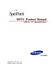
AT8xC51SND1C Firmware
Package
.............................................................................................
User Guide
-2
4209B–MP3–06/03
AT8xC51SND1C Firmware Package User Guide
Section 1
Introduction ........................................................................................... 1-1
1.1
1.2
1.3
Document History......................................................................................1-1
References................................................................................................1-1
Abbreviations ............................................................................................1-1
Section 2
Installation............................................................................................. 2-3
2.1
2.2
2.3
2.4
Architecture ...............................................................................................2-3
Firmware Configuration...........................................................................2-10
SBC LibrariesInterface ............................................................................2-12
Mass Storage Drivers..............................................................................2-13
Section 3
Operating Description ......................................................................... 3-15
3.1
3.2
3.3
3.4
3.5
3.6
3.7
3.8
3.9
Firmware Package User Guide
Overview .................................................................................................3-15
Keypad Assignment ................................................................................3-15
Firmware Upgrade ..................................................................................3-15
Start-Up...................................................................................................3-15
Mode Selection .......................................................................................3-16
Song Operating Mode .............................................................................3-16
Voice Operating Mode ............................................................................3-19
Tool Operating Mode ..............................................................................3-20
Mass Storage Operating Mode ...............................................................3-22
1
4209B–MP3–06/03
Section 1
Introduction
The AT89C51SND1C demonstration firmware is part of the AT8xC51SND1C starter kit.
This document is the user’s guide of the AT89C51SND1C demonstration firmware. It is
based on the development board V2.1 or V2.2.
1.1
Document
History
Rev
1.2
References
Pages
Purpose of Modifications
Date
A
All
Document creation based on V1.2.x user’s manual.
Support for AT89C51SND1C.
Oct. 22, 2002
B
All
New firmware architecture description
May. 28, 2003
n AT8xC51SND1C Datasheet
n AT89C51SND1C Errata Sheet
n AT8xC51SND1 Development Board User’s Guide
1.3
Abbreviations
n MP3: MPEG layer 3
n MMC: MultiMediaCard®
n DF: Atmel on-board DataFlash memories
n NF: NAND Flash memories
n CF: CompactFlash™ memories
n USB: Universal Serial Bus
n FAT: File Allocation Table
n SBC: SCSI Block Command
Firmware Package User Guide
1-1
Rev. 4209B–MP3–06/03
-2
4209B–MP3–06/03
Firmware Package User Guide
Installation
Section 2
Installation
The firmware package is delivered in a zip file: snd1c-xxxx-yyy-zzz-A_B_C.zip that
extracts in an Atmel\ directory.
2.1
Architecture
2.1.1
Overview
Figure 2-1 shows the organization of the Atmel\snd1c-xxxx-yyy-zzz-A_B_C directory.
The following sections detail the content of the sub-directories.
Figure 2-1. Atmel\snd1c-xxxx-yyy-zzz-A_B_C Directory Organization
Atmel\snd1c-xxxx-yyy-zzz-A_B_C\
doc\
lib_mcu\
lib_demod\ or lib_refd\
lib_storage\
modules\
usb_ms_drv\
The project name is defined as follow:
snd1c-xxx-yyy-zzz-A_B_C
where
xxx can be:
n “refd” for reference design based project
n “demo” for development board based project
yyy describes the type of on-board memory used. yyy can be:
n “nf” for NAND Flash memory
n “df” for Data Flash memory
Firmware Package User Guide
2-3
4209B–MP3–06/03
Installation
zzz is optional and describes the type of card memory used. zzz can be:
n “mmc” for MultiMediaCard memory
n “smc” for SmartMedia® Card memory
n “sd” for Secure Digital Card memory
For IDE/ATAPI projects, such as Hard Disk Drive, Compact Disc Reader or Compact
Flash, project tag is
snd1c-xxx-ide-A_B_C
A_B_C is the version number of the package. A, B and C are digits.
– A gives the major revision number.
– B gives the minor revision number and a state of the revision:
even number = stable version
odd number = non stable version (used during developments)
– C gives the patch revision number.
As shown in Figure 2-2, in addition to subdirectories, the project_tag\ directory contains
all the demonstration firmware core files and some important companion files giving
information on the demonstration firmware. Please read these files carefully.
This directory contains the Keil™ µ-vision2 project files, the executable file in Intel™
“.hex” format, the config.h file. Depending on the demo, more than one “.hex” and µvision2 project files can be found under this directory:
Figure 2-2. snd1c-xxxx-yyy-zzz-A_B_C\ File Organization
snd1c-xxxx-yyy-zzz-A_B_C\
2-4
4209B–MP3–06/03
config.h
main.c
scheduler.c
scheduler.h
startup.a51
variable.c
isp.a51
CHANGES.txt
INSTALL.txt
LICENSE.txt
NEWS.txt
README.txt
player_xxx.uv2
player_yyy.hex
Firmware Package User Guide
Installation
2.1.2
usb_ms_drv
Directory
As shown in Figure 2-3, the win_drv directory contains the Windows 98™ driver for the
USB mass storage application. The ‘readme’ files gives some advice on how to install
drivers on windows 98 ™ platform and how to mount the removable disk on Linux™
platform.
Figure 2-3. usb_ms_drv Directory Organization
usb_ms_drv\
2.1.3
lib_mcu Directory
atusbms.zip
readme.txt
readme_linux.pdf
As shown in Figure 2-4, the lib_mcu directory is organized into sub-directories that contain the low-level drivers of the AT89C51SND1C peripherals.
The lib_mcu directory also contains the following files:
n c51_drv.h: this header file contains macro functions able to configure c51 core
features such as clock mode, ERAM size, global interrupt, etc.
n compiler.h: this header file contains new type definitions, general purpose constants
and macro functions able to get rid of compiler type.
n regsnd1.h: this header file contains special function registers and bit definition of the
AT8xC51SND1C products.
n extsnd1.h: this header file contains mask definitions for special function registers of
the AT8xC51SND1C products.
Firmware Package User Guide
2-5
4209B–MP3–06/03
Installation
Figure 2-4. lib_mcu Directory Organization
lib_mcu\
adc\
adc_drv.c
adc_drv.h
aud\
aud_drv.c
aud_drv.h
clock\
clock.c
clock.h
kbd\
kbd_drv.c
kbd_drv.h
mmc\
mmc_drv.c
mmc_drv.h
mp3\
mp3_drv.c
mp3_drv.h
pll\
pll_drv.h
spi\
spi_drv.c
spi_drv.h
timer\
timer_drv.c
timer_drv.h
usb\
usb_drv.c
usb_drv.h
wdt\
wdt_drv.h
c51_drv.h
compiler.h
regsnd1.h
extsnd1.h
2.1.4
lib_demob Directory
As shown in Figure 2-5, the lib_demob directory is organized into sub-directories that
contain the low-level drivers of the AT8xC51SND1C development board peripherals.
The lib_demob directory also contains the following file:
n board.h: this header file contains definitions of the board hardware such as LCD
address, On-board Flash chip select ports, etc.
Figure 2-5. lib_demob Directory Organization
lib_demob\
dac\
dac_drv.h
lcd\
lcd_drv.c
lcd_drv.h
board.h
2.1.5
lib_refd Directory
As shown in Figure 2-6, the lib_refd directory is organized into sub-directories that contain the low-level drivers of the AT8xC51SND1C reference design peripherals.
The lib_refd directory also contains the following file:
n board.h: this header file contains definitions of the reference design hardware such as
On-board Flash chip select ports…
2-6
4209B–MP3–06/03
Firmware Package User Guide
Installation
Figure 2-6. lib_refd Directory Organization
lib_refd\
dac\
dac_drv.h
board.h
2.1.6
lib_mem Directory
As shown in Figure 2-7, the lib_mem directory is organized in sub-directories that contain the high-level drivers of memories or cards that can be connected to the
AT8xC51SND1C products.
Figure 2-7. lib_mem Directory Organization
lib_mem\
df\
df.c
df.h
mmc\
mmc.c
mmc.h
nf_1x_521b\
nf.c
nf.h
nf_drv.c
nf_drv.h
nf_drv_load.a51
nf_readme.txt
xxx\
For NAND Flash based application, some companion files give information on the demonstration firmware (reserved disk space feature or NAND Flash installation for
example).
NAND flash directories contain also a nf_readme.txt file.
Please read these files carefully.
MMC driver supports Multiple Block mode operations. If there is no specific define in
config.h file, the driver will be configured in Single Block mode. To set the Multiple Block
mode operation, add this line in config.h file:
#define MMC_CONFIG MMC_MULTI
Firmware Package User Guide
2-7
4209B–MP3–06/03
Installation
2.1.7
lib_storage
Directory
As shown in Figure 2-8, the lib_storage directory contains the libraries for SBC mass
storage support. In order to standardize the interfaces and to keep confidentiality on
these modules embedded SCSI modules are delivered in library form (source code not
delivered).
SBC module is composed of the following libraries:
n sbc.lib
This lib contains the common (not memory dependant) SBC functions.
n sbc_df.lib
This lib contains the specific SBC functions for DataFlash support.
n sbc_mmc.lib
This lib contains the specific SBC functions for MultiMediaCard support.
n sbc_nf.lib
This lib contains the specific SBC functions for NAND Flash support.
n sbc_smc.lib
This lib contains the specific SBC functions for SmartMediaCard support.
n sbc_cf.lib
This lib contains the specific SBC functions for CompactFlash support.
n sbc_atapi.lib
This lib contains the specific SBC functions for ATAPI devices (like CompactDisc
Reader) support.
n sbc_hdd.lib
This lib contains the specific SBC functions for Hard Disk Drive support.
n sbc_sd.lib
This lib contains the specific SBC functions for SD support.
Information on how to interface with those libraries is given in Section 2.3.
Figure 2-8. lib_storage Directory Organization
lib_storage\
sbc.h
sbc.lib
sbc_df.lib
sbc_mmc.lib
sbc_nf.lib
sbc_smc.lib
sbc_xxx.lib
2.1.7.1
doc Directory
2-8
4209B–MP3–06/03
The \doc directory contains the user’s guide of the firmware in PDF format.
Firmware Package User Guide
Installation
2.1.7.2
modules Directory
As shown in Figure 2-9, the modules directory is organized in sub-directories that contain files such as system header and source files, task header and source file.
Figure 2-9. modules Directory Organization
modules\
display\
file\
kbd\
kbd_task.c
kbd_task.h
mass\
usb_task.c
usb_task.h
sbc.h
hard.h
mem_task.c
mem_task.h
mem\
mode\
mode_task.c
mode_task.h
song\
song_drv.c
song_drv.h
song_task.c
song_task.h
tool\
tool_task.c
tool_task.h
voice_drv.c
voice_drv.h
voice_task.c
voice_task.h
voice\
Firmware Package User Guide
disp.c
disp.h
disp_task.c
disp_task.h
led_task.c (for reference design)
led_task.h (for reference design)
led.h (for reference design)
fat.c
fat.h
fat32.c
fat32.h
file.c
file.h
fs.h
fs_readme.txt
fs_variable.c
iso9660.c
iso9660.h
fs.h
wav.h
2-9
4209B–MP3–06/03
Installation
2.2
Firmware
Configuration
There are two files that are used to configure the firmware:
n the “config.h” located under snd1c-xxxx-yyy-zzz-A_B_C\ directory used to configure
the library/drivers as detailed in each driver header files.
n the “board.h” located under lib_demob\ directory used to configure the board type
between V2.1 or V2.2 and the component information of the board.
Note: When working with the starter kit, only the board type has to be configured,
component configuration must not be changed.
2.2.1
USB IDs
Three IDs are available for configuration by the user in config.h file:
n Vendor ID
n Product ID
n Release Number ID
According to USB Organization: “Vendor ID (VID) is owned by the vendor company and
is assigned and maintained by the USB-IF only. E-mail [email protected] for more information on USB-IF membership and obtaining a VID”.
Atmel allows limited usage of its VID (03EBh) during product development phase. Customer use of the Atmel Vendor ID is not guranteed by Atmel. The customer must use its
own Vendor ID for production.
2.2.2
USB Mass Storage
Strings
Six strings are available for configuration by user in config.h file. Those strings are
printed during USB drivers installation and during disk drivers status report in host
system:
n USB_MANUFACTURER_NAME unicode character string
n USB_MN_LENGTH number of unicode character
n USB_PRODUCT_NAME at least 12 unicode characters string
n USB_PN_LENGTH number of unicode characters
n USB_SERIAL_NUMBER at least 12 unicode characters string
n USB_SN_LENGTH number of unicode character
n SBC_VENDOR_ID 8 ASCII characters string
n SBC_PRODUCT_ID 16 ASCII characters string
n SBC_REVISION_ID 4 ASCII characters string
2.2.3
File system
Demonstration firmware supports 3 different file systems:
n FAT12/16
n FAT32
n ISO9660
File system configuration is done in the config.h file. For further information, please read
fs_readme.txt file under \modules\files directory.
2-10
4209B–MP3–06/03
Firmware Package User Guide
Installation
2.2.4
Memory type
Demonstration firmware supports different memory:
n MultiMedia Card
n SmartMedia Card
n Compact Flash
n NAND Flash
n DataFlash
n SD card
n Hard Disk Drive
n Compact Disk
Memory type definition must be set in config.h file. Pin out definition is defined in board.h
file.
There is two kinds of memory management:
n On-board memory
n Card memory
This allows 3 combinations:
n project with on-board memory alone
n project with card memory alone
n project with both on-board memory and card memory.
For example:
#define MEM_CHIP_TYPE CHIP_NF
#define MEM_CARD_TYPE CARD_MMC
This lines will configure memory type as:
n NAND Flash for on-board memory.
n MultiMedia Card for card memory.
Firmware Package User Guide
2-11
4209B–MP3–06/03
Installation
2.3
SBC Libraries
Interface
SBC module is composed of the following libraries:
n sbc.lib: this lib contains the common (not memory dependant) SBC functions.
n sbc_df.lib: this lib contains the specific SBC functions for DataFlash support.
n sbc_mmc.lib: this lib contains the specific SBC functions for MultiMediaCard support.
n sbc_nf.lib: this lib contains the specific SBC functions for NAND Flash support.
n sbc_smc.lib: this lib contains the specific SBC functions for SmartMediaCard support.
n sbc_atapi.lib: this lib contains the specific SBC functions for ATAPI support. If there is
only one memory, don’t add sbc.lib in the project file.
n sbc_cf.lib: this lib contains the specific SBC functions for CompactFlash support.
n sbc_hdd.lib: this lib contains the specific SBC functions for Hard Disk Drive support.
2.3.1
Global Variables
n gl_sbc_wr_busy
1-bit write activity, set to ON by library, must be set to OFF by consuming task (see
disp_task.c).
n gl_sbc_rd_busy
1-bit read activity, set to ON by library, must be set to OFF by consuming task (see
disp_task.c).
n gl_sbc_wr_protect
1-bit write protection, set to ON or OFF before calling the library command browser
(see usb_task.c).
n dCBWDataTransferLength
4-byte unsigned USB variable (declared in usb_task.c).
n gl_sbc_vendor_id
8-char table in code space (see Section 2.2.2 for configuration).
n gl_sbc_product_id
16-char table in code space (see Section 2.2.2 for configuration).
n gl_sbc_revision_id
4-char table in code space (see Section 2.2.2 for configuration).
2.3.2
Internal Library
Functions
In the following items xxx may represent df, nf, smc, cf… depending on the memory
library.
n void sbc_xxx_init (void)
Memory dedicated SBC support initialization function.
n void sbc_command_xxx (void)
Memory dedicated SBC support command parser function.
2-12
4209B–MP3–06/03
Firmware Package User Guide
Installation
2.3.3
External Library
Functions
In the following items xxx may represent df, nf, smc, cf… depending on the memory
library.
n xxx_block_size_0(), xxx_block_size_1(), xxx_block_size_2(), xxx_block_size_3():
4-byte unsigned block size (byte unit) reported byte by byte.
n xxx_disk_size_0(), xxx_disk_size_1(), xxx_disk_size_2(), xxx_disk_size_3():
4-byte unsigned disk size (block unit) reported byte by byte.
n xxx_read_open(void), xxx_read_sector(sector_nb), xxx_read_close(void)
functions implemented in memory driver module.
n xxx_write_open(void), xxx_write_sector(sector_nb), xxx_write_close(void)
functions implemented in memory driver module.
n xxx_check_presence()
function implemented in removable memory (card) driver module only.
2.4
Mass Storage
Drivers
2.4.1
Windows Drivers
No specific mass storage driver installation is requested when using Windows 2000™,
Windows ME™, and Windows XP™. Each system loads the generic mass storage driver
when plugging the development board to the PC.
As no generic driver is available under Windows 98SE™ system, Atmel has developed
its own mass storage driver to support this operating system. This driver is based on 3
files: atusbms.sys, atusbpdr.pdr and atusbms.inf. Install information is provided in
readme.txt file under usb_ms_drv directory.
2.4.2
Linux Drivers
Install information for linux is provided in readme_linux.pdf file under usb_ms_drv
directory.
Firmware Package User Guide
2-13
4209B–MP3–06/03
-14
4209B–MP3–06/03
Firmware Package User Guide
Operating Description
Section 3
Operating Description
3.1
Overview
The following sections describe demo-df-mmc firmware operating modes. Some slight
changes may apply for other demonstration firmware (icon, file system type, ...).
3.2
Keypad
Assignment
Figure 3-1 shows the board’s keypad assignment, one key is left free of functionality for
user’s usage.
Figure 3-1. Keypad Assignment
MODE
3.3
Firmware
Upgrade
A hidden operating mode is available to upgrade the firmware without using the ISP
hardware condition. This mode is entered by pressing simultaneously the grayed key as
shown in Figure 3-1 while powering the board or pressing the reset button. The upgrade
screen is then displayed to inform user of boot loader execution.
Figure 3-2. Firmware Upgrade Screen
Firmware Upgrade
Firmware can then be upgraded using the generic Atmel FLIP tool.
3.4
Start-Up
The AT89C51SND1C firmware starts with a splash screen giving the version(1) of the
firmware (see Figure 3-3). This screen is displayed during few seconds but can be
skipped by pressing any key.
Note:
Firmware Package User Guide
1. Version displayed is composed of three digits. Please refer to chapter 2.1.1 for further
information
3-15
4209B–MP3–06/03
Operating Description
Figure 3-3. Splash Screen
AT8x51SND1 DEMO
FIRMWARE V3.0.X
3.5
Mode Selection
After the set-up phase, the firmware enters the song operating mode. In all operating
modes, the mode can be sequentially changed using the “Mode” key with the following
order:
n Song mode
n Voice mode
n Tool mode
Mass Storage operating mode is entered automatically when connecting the board to
the PC through the USB connection.
All these operating modes are detailed in the following sections.
3.6
Song Operating
Mode
This mode is the MP3 song player. It gathers together all the standard features of a portable player. It displays the FAT file names in DOS 8.3 or VFAT long format.
Figure 3-4. Display in Song Playing Mode
Player Memory Repeat Sound
Icon
Icon
Icon
Level
Playing
Time
Lock Status
15 0:00
Song Name.mp3
Player State
Song Name
3.6.1
Keypad Functions
Table 1 details the functionality of each key depending on the current state.
Table 1. Song Mode Key Function
Key
Description
Sound Control
Select the volume or bass or medium or treble control.
Memory Control (stop state)
Make a selection between the on-board FLASH memory, the MMC 1 or the
MMC 2 card.
Next Song (play state)
Play next mp3 file in current directory.
Next Selection (stop state)
Select next mp3 file or directory in current directory.
3-16
4209B–MP3–06/03
Firmware Package User Guide
Operating Description
Key
Description
Previous Song (play state)
Play previous mp3 file or directory in current directory.
Previous Selection (stop state)
Select previous mp3 file or directory in current directory.
Play (stop state)
Start playing of selected song.
Pause (play state)
Suspend playing of song.
Enter (stop state)
Enter the selected directory.
MODE
Stop (play state)
Stop playing of song.
Mode (stop state)
Exit the song operating mode and go to the voice operating mode.
Increase Control
Increase global volume.
Increase bass volume.
Increase medium volume.
Increase treble volume.
Decrease Control
Decrease global volume.
Decrease bass volume.
Decrease medium volume.
Decrease treble volume.
Parent Directory (stop state)
Go to the parent directory.
Repeat (play state)
Repeat playing from the beginning after the last song toggle key.
Repeat A/B (play state)
First press sets A marker, while second press sets B marker and jumps
back to A marker.
Erase (stop state)
Pressing this key for more than 3 seconds removes the selected song file
from FAT.
Keypad Lock Control
Lock or unlock the keypad.
3.6.2
Memory Selection
The memory selection is done using the “Memory control” key. On-board memory is
selected by default, pressing the “Memory control” key selects sequentially the MMC1
memory, the MMC2 memory then the on-board memory. If present, selected memory is
displayed as shown in Table 2.
Table 2. Selected Memory Status
Icon
Description
On-Board Memory
On-board memory is selected.
MMC1
MMC card 1 is selected.
Firmware Package User Guide
3-17
4209B–MP3–06/03
Operating Description
Icon
Description
MMC2
MMC card 2 is selected.
3.6.3
Song Player State
The player can take 5 different states as detailed in Table 3.
Table 3. Song Player States
Icon
Description
SONG
MP3 file selected (stop state).
DIRECTORY
Directory selected (stop state)
PLAY
Selected song under playing.
PAUSE
Selected song paused.
ERROR
Selected memory is not formatted.
3.6.4
Song Name
When entering song operating mode or after selecting other memory, the first song or
directory of the root directory is displayed. If the name is more than 14 bytes long, it is
scrolled on the display from right to left. If the root directory is empty (no MP3 file or no
directory) ‘--’ is displayed instead of name.
If memory is not formatted, the error state is displayed. Please refer to Section 3.8 to format the memory.
3.6.5
Playing Time
During song playing, time is displayed as minute:second.
3.6.6
Sound Control
Sound selection is done by pressing the “Sound” key. The level of each selected sound
is displayed on the screen. Sound adjustment is performed by pressing the “Increase” or
“Decrease” key.
3.6.7
Repeat Modes
Two repeat modes are available:
n Repeat A/B
n Auto Repeat
These modes are only selectable during song playing mode. Pressing the “Repeat” key
for more than half a second enables or disables the auto repeat feature. Pressing the
“Repeat” key once sets the A marker while pressing the “Repeat” key a second time
sets the B marker. Then song is played from A to B repeatedly.
Repeat modes are signalled to user using a small icon in the first line of the display (see
Figure 3-4) and as detailed in Table 4.
Table 4. Repeat Mode Status
Icon
Description
Auto Repeat
Endless Playing.
Repeat A/B
A marker is set.
3-18
4209B–MP3–06/03
Firmware Package User Guide
Operating Description
Icon
Description
Repeat A/B
B marker is set, repeat playing from A to B.
3.6.8
Song Erasing
In order to free-up memory for message recording, an erase function has been implemented. Pressing the “Erase” key, for more than 3 seconds, erases the currently
selected song.
3.7
Voice Operating
Mode
This mode is used to store voice messages.
Figure 3-5. Display in Voice Operating Mode
Voice Memory
Icon
Icon
Volume
Level
Playing
Time
Lock Status
2 0:00
VOICEOO1.WAV
Player/Recorder State
Message Name
3.7.1
File Format
Files created are compatible with windows™ pcm wav files and can be played using any
media player. File format is mono 8 Khz 8-bit leading to 64 Kbits/s, thus 8 Kbytes of
memory per second.
3.7.2
Keypad Functions
Table 5 details the functionality of each key depending on the current state.
Table 5. Voice Mode Key Function
Key
Description
Next Message
Select next voice message in memory.
Previous Message
Select previous voice message in memory.
Play (stop state)
Start playing of selected voice message.
Pause (play state)
Suspend playing of voice message.
Pause (record state)
Suspend recording of song message.
Stop (play state)
Stop playing of voice message.
MODE
Stop (record state)
Stop recording of voice message.
Mode (stop state)
Exit the voice operating mode and go to the tool operating mode.
Increase Control
Increase volume.
Decrease Control
Decrease volume.
Firmware Package User Guide
3-19
4209B–MP3–06/03
Operating Description
Key
Description
Record (stop state)
Start recording of a new voice message.
Erase (stop state)
Pressing this key for more than 3 seconds removes the selected voice
message from FAT.
Keypad Lock Control
Lock or unlock the keypad.
3.7.3
Message Recording
Pressing the “Record” key, creates a new “Voicexxx.wav” file in FAT then sampling is
started and message is recorded until the “Stop” key is pressed or end of memory is
reached. Up to 255 voice messages can be recorded in FAT.
3.7.4
Message Erasing
Pressing the “Erase” key, for more than 3 seconds, erases the currently selected
message.
3.7.5
Memory Selection
The memory selection is done using the “Memory control” key. On-board memory is
selected by default, pressing the “Memory control” key selects sequentially the MMC1
memory, the MMC2 memory then the on-board memory. If present, selected memory is
displayed as shown in Table 2.
3.7.6
Message
Player/Recorder
State
The voice player/recorder can take 5 different states as detailed in Table 6.
Table 6. Voice Player States
Icon
Description
STOP
No message under playing nor recording.
PLAY
Message is under playing.
PAUSE
Playing or recording is paused.
RECORD
Message is under recording.
ERROR
Selected memory is not formatted.
3.7.7
Message Name
When entering voice operating mode or after selecting other memory, the wave file
name is displayed. If the root directory of the on-board memory does not contain any
“VOICEnnn.WAV” file, ‘--’ is displayed instead of the file name.
If memory is not formatted, the error state is displayed.
3.7.8
Playing Time
During memo playing, time is displayed as minute:second.
3.7.9
Volume Control
A five step volume control is implemented and is adjusted by pressing the “Increase” or
“Decrease” key.
3.8
Tool Operating
Mode
This operating mode is a menu composed of two items. It is used to format the memory
with or without voice files.
3-20
4209B–MP3–06/03
Firmware Package User Guide
Operating Description
Figure 3-6. Display in Tool Operating Mode
Tool
Icon
Memory
Icon
Lock Status
Format...
Item Execution State
Item Name
3.8.1
Keypad Functions
Table 7 details the functionality of each key depending on the current state.
Table 7. Tool Mode Key Function
Key
Description
Execute
Execute the selected item.
MODE
Mode
Exit the tool operating mode and go to the song operating mode.
Keypad Lock Control
Lock or unlock the keypad.
3.8.2
Memory Selection
The memory selection is done using the “Memory control” key. On-board memory is
selected by default, pressing the “Memory control” key selects sequentially the MMC1
memory, the MMC2 memory then the on-board memory. If present, selected memory is
displayed as shown in Table 2.
3.8.3
Tool State
The tool operating mode can take 2 different states as detailed in Table 8.
Table 8. Tool States
Icon
Description
READY
Selected function is ready for execution.
BUSY
Selected function is under execution.
3.8.4
‘Format’ Item
Firmware Package User Guide
The ‘format’ function allows memory formatting in FAT12 or FAT16 depending on the
memory size. For example, on board DataFlash will be formatted in FAT12 for V2.1
board (16 Mbytes) or FAT16 for board V2.2 (32 Mbytes).
This format function is compliant with MMC and SMC recommendations. Using other
format specially for NF or SMC may lead to decrease the data transfer rate in mass storage mode.
3-21
4209B–MP3–06/03
Operating Description
3.9
Mass Storage
Operating Mode
Firmware V3.0.X and later support USB mass storage on the following platforms:
n Win98 through Atmel drivers
n Win2000(1) (2)/ME/XP
n MAC OS(1) V9 and later
n Linux
Note:
1. These platforms do not provide multi-drive support
2. Service Pack 3 of Win2000 now allows multi-drive support
When the development board is plugged to the host through the USB cable, the currently selected operating mode is stopped and the download operating mode is entered
(see Figure 3-7). When disconnecting from the host, the song operating mode is automatically selected.
Depending on the platform multi-drive support, one or two removable disks automatically appear in the explorer window. Content of the selected memory is then made
accessible for read/write operations through the explorer.
Figure 3-7. Display in Download Operating Mode
USB
Icon
Memory
Icon
Write Protect Status
Download Indicator
3.9.1
Keypad Functions
As soon as development board is connected to the PC, player is not controllable
through the keypad until it is unplugged from the PC.
3.9.2
Memory Selection
Memory selection is done when entering the download operating mode.
On platforms that do not support multi-drive, the selected memory (refer to icon) is:
n the MMC if at least one MMC card is present in the stack
n the on board memory if no MMC card is present in the stack
The selected memory stays selected until USB is unplugged.
On platforms that support multi-drive, the selected memory is:
n the on board memory on the first mounted drive
n the MMC on the second mounted drive
When MMC card is removed and plugged again, and depending on the operating system, it may be necessary to press the F5 key to refresh the explorer content.
3.9.3
Write Protection
3-22
4209B–MP3–06/03
If keypad is locked before entering the download operating mode, file write will be forbidden and a message will inform user that the device is write protected in case of
attempted file write. Due to SCSI mass storage implementation, write protection must be
set prior to connecting the device to USB. Any change of the lock key during connection
will have no effect.
Firmware Package User Guide
Operating Description
3.9.4
Download State
The download or upload activity is signalled to user by blinking the download indicator.
Do not unplug the player while this indicator is blinking, this may result in file system corruption and may request new formatting of the memory.
Table 9. Download States
Icon
Description
Busy
Host is writing a file to memory.
Host is reading a file from memory.
Firmware Package User Guide
3-23
4209B–MP3–06/03
Atmel Corporation
2325 Orchard Parkway
San Jose, CA 95131
Tel: 1(408) 441-0311
Fax: 1(408) 487-2600
Regional Headquarters
Europe
Atmel Sarl
Route des Arsenaux 41
Case Postale 80
CH-1705 Fribourg
Switzerland
Tel: (41) 26-426-5555
Fax: (41) 26-426-5500
Asia
Room 1219
Chinachem Golden Plaza
77 Mody Road Tsimshatsui
East Kowloon
Hong Kong
Tel: (852) 2721-9778
Fax: (852) 2722-1369
Japan
9F, Tonetsu Shinkawa Bldg.
1-24-8 Shinkawa
Chuo-ku, Tokyo 104-0033
Japan
Tel: (81) 3-3523-3551
Fax: (81) 3-3523-7581
Atmel Operations
Memory
2325 Orchard Parkway
San Jose, CA 95131
Tel: 1(408) 441-0311
Fax: 1(408) 436-4314
RF/Automotive
Theresienstrasse 2
Postfach 3535
74025 Heilbronn, Germany
Tel: (49) 71-31-67-0
Fax: (49) 71-31-67-2340
Microcontrollers
2325 Orchard Parkway
San Jose, CA 95131
Tel: 1(408) 441-0311
Fax: 1(408) 436-4314
La Chantrerie
BP 70602
44306 Nantes Cedex 3, France
Tel: (33) 2-40-18-18-18
Fax: (33) 2-40-18-19-60
ASIC/ASSP/Smart Cards
1150 East Cheyenne Mtn. Blvd.
Colorado Springs, CO 80906
Tel: 1(719) 576-3300
Fax: 1(719) 540-1759
Biometrics/Imaging/Hi-Rel MPU/
High Speed Converters/RF Datacom
Avenue de Rochepleine
BP 123
38521 Saint-Egreve Cedex, France
Tel: (33) 4-76-58-30-00
Fax: (33) 4-76-58-34-80
Zone Industrielle
13106 Rousset Cedex, France
Tel: (33) 4-42-53-60-00
Fax: (33) 4-42-53-60-01
1150 East Cheyenne Mtn. Blvd.
Colorado Springs, CO 80906
Tel: 1(719) 576-3300
Fax: 1(719) 540-1759
Scottish Enterprise Technology Park
Maxwell Building
East Kilbride G75 0QR, Scotland
Tel: (44) 1355-803-000
Fax: (44) 1355-242-743
e-mail
[email protected]
Web Site
http://www.atmel.com
Disclaimer: Atmel Corporation makes no warranty for the use of its products, other than those expressly contained in the Company’s standard
warranty which is detailed in Atmel’s Terms and Conditions located on the Company’s web site. The Company assumes no responsibility for any
errors which may appear in this document, reserves the right to change devices or specifications detailed herein at any time without notice, and
does not make any commitment to update the information contained herein. No licenses to patents or other intellectual property of Atmel are
granted by the Company in connection with the sale of Atmel products, expressly or by implication. Atmel’s products are not authorized for use
as critical components in life support devices or systems.
© Atmel Corporation 2003. All rights reserved. Atmel© is a registered trademark of Atmel Corporation.
DataFlash ™ is a trademark of Atmel Corporaion. Windows98 ™, WindowsXP ™, Windows2000 ™, and
Windows98SE™ are trademarks of Microsoft Corporation. Linux™ is a trademark of Linus Torvalds. Intel ™ is a
trademark of Intel Corporation. CompactFlash ™ is a trademark of CompactFlash Association. SmartMedia ® is a
registered trademark of Toshiba Corporation.
Other terms and product names in this document may be trademarks of others.
Printed on recycled paper.