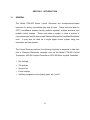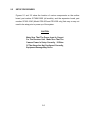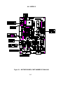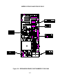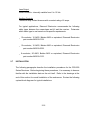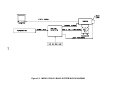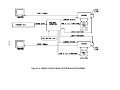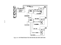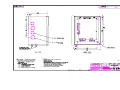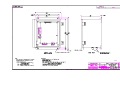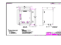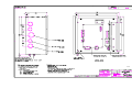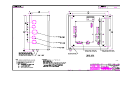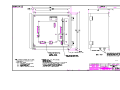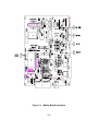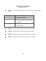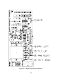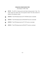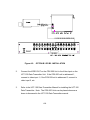
1
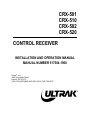
CRX-501 CRX-510 CRX-502 CRX-520 CONTROL RECEIVER INSTALLATION AND OPERATION MANUAL MANUAL NUMBER 517584-1960 ® Ultrak , Inc. 4465 Coonpath Road Carroll, OH 43112 (740) 756-9222•(800) 443-6681•FAX (740) 756-4237 1999 BY ULTRAK®, INC. ALL RIGHTS RESERVED PRINTED IN THE UNITED STATES OF AMERICA ULTRAK, INCORPORATED 4465 COONPATH ROAD CARROLL, OHIO 43112 (740) 756-9222 ALL RIGHTS RESERVED. NO PART OF THIS PUBLICATION MAY BE REPRODUCED BY ANY MEANS WITHOUT WRITTEN PERMISSION FROM ULTRAK, INCORPORATED. THE INFORMATION IN THIS PUBLICATION IS BELIEVED TO BE ACCURATE IN ALL RESPECTS. HOWEVER, ULTRAK, INCORPORATED CANNOT ASSUME RESPONSIBILITY FOR ANY CONSEQUENCES RESULTING FROM THE USE THEREOF. THE INFORMATION CONTAINED HEREIN IS SUBJECT TO CHANGE WITHOUT NOTICE. REVISIONS OR NEW EDITIONS TO THIS PUBLICATION MAY BE ISSUED TO INCORPORATE SUCH CHANGES. Issue 1, Revision A - April 1995 -- Added Appendix A for installing a CRX-500 Series Receiver with Option B1 or Option B2 installed Issue 1, Revision B - October 1995 - Added data and drawings for CRX502/220/X Control Receivers for 220 Vac pan and tilts Issue 1, Revision C - November 1995 - Corrected LED indicators for the expansion board Issue 1, Revision D - November 1995 - Corrected Figure 3-2 to match changed text in Revision C Issue 1, Revision E - February 1996 - Added table for lens zoom, focus, and common connections, changed Table 2-1 on page 2-23 to Table 2-2. Issue 1, Revision F - April 1996 - Added Model CRX-510/220/X. Issue 1, Revision G - April 1996 - Added CE Warning and Declaration (Note: As of 1/1/97 this product does not meet CE requirements) Issue 1, Revision H - August 1996 - updated installationd drawings 517584-1440 and 517588-1440. Issue 1, Revision I – July 1997 – added note for addressing unit for controlling auxiliary contacts and updated controller manual numbers. Issue 1, Revision J – July 1997 – added cross-reference for current model numbers Issue 1, Revision K – August 1998 – added note for ground connection for pan and tilt unit (ECR 11478) and changed coaxial cable distance for UCT option from <1500 feet to <800 feet. WARNING THIS IS A CLASS A PRODUCT. IN A DOMESTIC ENVIRONMENT, THIS PRODUCT MAY CAUSE RADIO INTERFERENCE IN WHICH CASE THE USER MAY BE REQUIRED TO TAKE ADEQUATE MEASURES. NOTE This Equipment Has Been Tested And Found To Comply With The Limits For A Class A Digital Device, Pursuant To Part 15 Of The FCC Rules. These Limits Are Designed To Provide Reasonable Protection Against Harmful Interference When The Equipment Is Operated In A Commercial Environment. This Equipment Generates, Uses, And Can Radiate Radio Frequency Energy And, If Not Installed And Used In Accordance With The Instruction Manual, May Cause Harmful Interference To Radio Communications. Operation Of This Equipment In A Residential Area Is Likely To Cause Harmful Interference In Which Case The User Will Be Required To Correct The Interference At His Own Expense. TABLE OF CONTENTS Page SECTION 1. INTRODUCTION ....................................................................................1-1 1.1 GENERAL..........................................................................................................1-1 1.2 MODELS............................................................................................................1-2 1.3 OPTIONS...........................................................................................................1-4 1.4 SPECIFICATIONS.............................................................................................1-5 SECTION 2. SETUP AND INSTALLATION ................................................................2-1 2.1 GENERAL..........................................................................................................2-1 2.2 SITE PREPARATION ........................................................................................2-1 2.2.1 OPERATING ENVIRONMENT CONSIDERATIONS....................................2-1 2.2.2 POWER AND GROUNDING REQUIREMENTS. .........................................2-1 2.2.3 STORAGE PROCEDURES..........................................................................2-2 2.3 HANDLING PROCEDURES ...................................................................................2-3 2.4 PERSONNEL SAFETY......................................................................................2-4 2.5 SETUP PROCEDURES ....................................................................................2-5 2.5.1 120 VAC OR 220 VAC INPUT POWER.......................................................2-8 2.5.2 CAMERA POWER SETUP. .........................................................................2-9 2.5.3 RECEIVER ADDRESS...............................................................................2-10 2.5.4 TERMINATE RECEIVE COMMUNICATIONS............................................2-13 2.5.5 LENS ZOOM, FOCUS, AND IRIS SPEED CONTROL SETUP..................2-13 2.5.6 AUXILIARY CONTACT SETUP. ................................................................2-14 2.5.7 IRIS DRIVE VOLTAGE. .............................................................................2-15 2.6 CABLING REQUIREMENTS ...........................................................................2-15 2.6.1 RS422 COMMUNICATION CABLE............................................................2-15 2.6.2 POWER INPUT, PAN AND TILT CONTROL, LENS CONTROL, AND CAMERA POWER CABLE. ............................................................................................................2-15 2.7 INSTALLATION ...............................................................................................2-16 2.7.1 RS-422 COMMUNICATION CONNECTIONS............................................2-20 i TABLE OF CONTENTS (CONT) Page 2.7.1.1 Daisy-Chain Wiring. ..............................................................................2-21 2.7.2 POWER CONNECTIONS. .........................................................................2-22 2.7.3 PAN AND TILT CONNECTIONS................................................................2-22 2.7.4 CAMERA POWER. ....................................................................................2-24 2.7.5 LENS CONNECTIONS...............................................................................2-25 2.7.5.1 Auto Iris Lens ........................................................................................2-26 2.7.5.2 Motorized Manual Iris Lens ...................................................................2-26 2.7.5.3 Selectable Auto/Manual Iris ..................................................................2-27 2.7.6 2.8 AUXILIARY FUNCTIONS...........................................................................2-27 INSTALLATION DRAWINGS ..........................................................................2-29 SECTION 3. OPERATION ..........................................................................................3-1 3.1 GENERAL..........................................................................................................3-1 3.2 CONTROLS AND INDICATORS ..................................................................................3-1 3.3 OPERATING PROCEDURE .......................................................................................3-6 SECTION 4. MAINTENANCE .....................................................................................4-1 4.1 GENERAL..........................................................................................................4-1 4.2 MAINTENANCE PROCEDURES .................................................................................4-1 APPENDIX A. DATA RECEIVER BOARD OPTION .................................................. A-1 A.1 GENERAL......................................................................................................... A-1 A.2 INSTALLATION...................................................................................................... A-1 LIST OF FIGURES Page Figure 2-1. MOTHER BOARD, PART NUMBER 517484-X040 ..................................2-6 Figure 2-2. EXPANSION BOARD, PART NUMBER 517482-1040 .............................2-7 Figure 2-3. MODEL CRX-501 BASIC SYSTEM BLOCK DIAGRAM .........................2-17 Figure 2-4. MODEL CRX-502 BASIC SYSTEM BLOCK DIAGRAM .........................2-18 ii LIST OF FIGURES (CONT) Page Figure 2-5. SYSTEM WITH MULTIPLE RECEIVERS AND VIDEO SWITCHER ......2-19 Figure 3-1. Mother Board Indicators............................................................................3-2 Figure 3-2. Expansion Board Indicators ......................................................................3-4 Figure A-1. TYPICAL INSTALLATION FOR CRX-500 SERIES RECEIVER WITH OPTION B1 OR B2 INSTALLED............................................................. A-2 Figure A-2. OPTION B1 OR B2 INSTALLATION .................................................... A-4 LIST OF DRAWINGS Installation, CRX-501 Pan & Tilt Receiver NEMA 1 (Indoor) (D/N 517584-1440) .....2-31 Installation, CRX-510 Pan & Tilt Receiver NEMA 4 (Outdoor) (D/N 517584-5440)....2-32 Installation, CRX-510/220/X Pan & Tilt Receiver NEMA 4 (Outdoor) 220 Vac Input, 220 Vac Pan & Tilt (D/N 517584-9440) .............................................2-33 Installation, CRX-502 Pan & Tilt Receiver NEMA 1 (Indoor) (D/N 517588-1440) ......2-34 Installation, CRX-502/220/X Pan & Tilt Receiver NEMA 1 (Indoor) (D/N 517588-9440).....................................................................................................2-35 Installation, CRX-520 Pan & Tilt Receiver NEMA 4 (Outdoor) (D/N 517588-5440)....2-36 LIST OF TABLES Table 2-1. CAMERA NUMBERS ...............................................................................2-11 Table 2-2. CRX-500 RECEIVER TO PAN AND TILT UNIT.......................................2-24 iii SECTION 1. INTRODUCTION 1.1 GENERAL The Model CRX-500 Series Control Receivers are microprocessor-based receivers for driving conventional pan and tilt units. These units are ideal for CCTV surveillance systems having multiple cameras, multiple monitors, and multiple control stations. These units allow a system to have a mixture of conventional pan and tilt devices and Diamond Electronics FastScan/SmartScan units. It may also be used as a single digital control system using one transmitter and one receiver. The Control Receiver performs the following functions in response to data sent from a Diamond Electronics controller such as the Model CTX-800 Control Transmitter, JAD-832 Joystick Controller or JPD-100 Series Joystick Controllers. • Pan left/right • Tilt up/down • Zoom in/out • Focus near/far • Auxiliary equipment control (lights, gates, etc.) on/off 1-1 1.2 MODELS There are four basic models available; CRX-501, CRX-510, CRX-502, and CRX520. Models CRX-501 and CRX-510 control one pan and tilt unit. Models CRX502 and CRX-520 can control two pan and tilt units. The pan and tilts have to have the same power requirements - 120 Vac, 220 Vac1, or 24 Vac @ 1 Amp; but the camera power requirements can be different - either 12 Vdc or 24 Vac @ 0.5 Amp. Models CRX-501 and CRX-502 are for indoor installations. The indoor control receivers are housed in a NEMA 1 enclosure. Models CRX-510 and CRX-520 are for outdoor installations. The outdoor control receivers are housed in a NEMA 4 enclosure. Each model provides two auxiliary contacts. The auxiliary contacts are latched contacts that can be normally open or normally closed. Model 1 Description Part Number CRX-501 or CRX-501/A 120 Vac Power Input, 120 Vac Pan and Tilt, Indoor Applications 517584-1040 CRX-501/24 or CRX-501/B 120 Vac Power Input, 24 Vac Pan and Tilt, Indoor Applications 517584-2040 CRX-501/X or CRX-501/A/X 220 Vac Power Input, 120 Vac Pan and Tilt, Indoor Applications 517584-3040 CRX-501/24/X or CRX-501/B/X 220 Vac Power, 24 Vac Pan and Tilt, Indoor Applications 517584-4040 The only models that can drive a 220 Vac pan and tilt unit are CRX-510/220/X and CRX-502/220/X. 1-2 Model Description Part Number CRX-510 or CRX-510A 120 Vac Power Input, 120 Vac Pan and Tilt, Outdoor Applications 517584-5040 CRX-510/24 or CRX-510/B 120 Vac Power Input, 24 Vac Pan and Tilt, Outdoor Applications 517584-6040 CRX-510/X or CRX-510/A/X 220 Vac Power Input, 120 Vac Pan and Tilt, Outdoor Applications 517584-7040 CRX-510/24/X or CRX-510/B/X 220 Vac Power Input, 24 Vac Pan and Tilt, Outdoor Applications 517584-8040 CRX-510/220/X 220 Vac Power Input, 220 Vac Pan an d Tilt, Outdoor Applications 517584-9040 CRX-502 or CRX-502/A 120 Vac Power Input, 120 Vac Pan and Tilt, Indoor Applications 517588-1040 CRX-502/24 or CRX-502/B 120 Vac Power Input, 24 Vac Pan and Tilt, Indoor Applications 517588-2040 CRX-502/X or CRX-502/A/X 220 Vac Power Input, 120 Vac Pan and Tilt, Indoor Applications 517588-3040 CRX-502/24/X or CRX-502/B/X 220 Vac Power Input, 24 Vac Pan and Tilt, Indoor Applications 517588-4040 CRX-502/220/X 220 Vac Power Input, 220 Vac Pan and Tilt, Indoor Applications 517588-9040 CRX-520 or CRX-520/A 120 Vac Power Input, 120 Vac Pan and Tilt, Outdoor Applications 517588-5040 CRX-520/24 or CRX-520/B 120 Vac Power Input, 24 Vac Pan and Tilt, Outdoor Applications 517588-6040 CRX-520/X or CRX-520/A/X 220 Vac Power Input, 120 Vac Pan and Tilt, Outdoor Applications 517588-7040 CRX-520/24/X or CRX-520/B/X 220 Vac Power Input, 24 Vac Pan and Tilt, Outdoor Applications 517588-8040 1-3 1.3 OPTIONS The following options are available for the CRX-500 Series Control Receivers. These options must be factory installed. • HEATER OPTION CRX-500/HTR - 120 Vac Heater CRX-500/HTR/X - 220 Vac Heater The heater option increases the low end temperature limit to -8°F (-22°C). • DATA RECEIVER BOARD OPTION NEMA 4 Outdoor control receiver NEMA 1 Indoor control receiver The data receiver board is used when the control data is sent across the video coax. This option requires the UCT-100 Data Transmitter Unit. Use Option B1 for indoor units. Use Option B2 for outdoor units. The outdoor option provides sealed BNC connectors. • AUTOMATIC/MANUAL IRIS CONTROL CRX-500/MIO The automatic/manual iris control option provides the operator manual control of the lens iris. 1-4 1.4 SPECIFICATIONS Power Input Requirements: Pan and Tilt Power Output: Fuse F1 Circuit Board and Auxiliaries: Fuse (F2) Pan and Tilt/Heater: Camera Power Output: Lens Power Output: Auxiliary Contacts: Communication Interface: Operating Distance: Operating Temperature: Storage Temperature: Humidity Limits: Dimensions: 120/220 Vac ±10%, 50/60 Hz, 1.5 Amps (max.) 120 Vac, 220 Vac, or 24 Vac, 1 Amp (max.) 120 Vac Power Input F1 - 1 Amp 250V 3AG 220 Vac Power Input F1 - 1/2 Amp 250V 3AG 120 Vac Power Input 1 Amp 250V 3AG (120 Vac) With heater option: 1.5 Amp 250V 3AG 220 Vac Power Input 1/2 Amp 250V 3AG With optional heater 1 Amp 250V 3AG 24 Vac or 12 Vdc @ 0.5 Amp (max.) Manual Iris (requires motorized iris lens or Option C installed in receiver and a lens modified for auto/manual iris) - ±6 to 12 Vdc @ 100 mA adjustable Zoom - ±6 to 12 Vdc @ 100 mA adjustable Focus - ±6 to 12 Vdc @ 100 mA adjustable Form C Relay (NO, NC, C) 6 Amp rating RS-422, 9600 baud 4000 ft. with recommended cable +32 °F to +122 °F (0 °C to +50 °C) With optional heaters -8 °F to +122 °F (-22 °C to +50 °C) -40 °F to +158 °F (-40 °C to +70 °C) 0 to 95% non-condensing CRX-501, NEMA 1, Indoor 8.0" W x 10.0" H x 6.06" D (203mm W x 254mm H x 154mm D) CRX-510, NEMA 4, Outdoor 8.0" W x 11.50" H x 6.18" D (203mm W x 292mm H x 157mm D) CRX-502, NEMA 1, Indoor 12.0" W x 12.0" H x 6.06" D (305mm W x 305mm H x 154mm D) 1-5 Dimensions (cont’d): Weight: Material: Finish: CRX-520, NEMA 4, Outdoor 12.0" W x 13.50" H x 6.18" D (305mm W x 343mm H x 157mm D) Model CRX-501, NEMA 1 15 lbs (6.8 kgs) Model CRX-510, NEMA 4 17 lbs (7.7 kgs) Model CRX-502, NEMA 1 24 lbs (10.9 kgs) Model CRX-520, NEMA 4 28 lbs (12.7 kgs) Outdoor: NEMA 4: 14 Gauge Steel Indoor: NEMA 1: 16 Gauge Steel Gray 1-6 SECTION 2. SETUP AND INSTALLATION 2.1 GENERAL This section describes the handling procedures, customer cabling requirements, setup procedures, and the installation procedures for the CRX-500 Series Control Receivers. 2.2 2.2.1 SITE PREPARATION Operating Environment Considerations. The control receiver is designed to operate within a computer-oriented environment. Maintain the environmental conditions as described in paragraph 1.4. 2.2.2 Power and Grounding Requirements. a. Power Requirements The CRX-500 Series Control Receivers require either a 120 Vac or 220 Vac, 50/60 Hz, 180 Watts. b. Grounding Requirements The control receiver must be connected to a true earth ground. This is very important for two reasons: 1. In the event of internal electrical faults, such as shorts, the entire fault current is carried to ground. This protects operating personnel from hazardous shock. 2-1 2. This ground connection provides a true ground reference for analog and digital circuits. All ground circuits must be treated with care. The system's safety ground should, via the shortest route, provide a dedicated safety/logic ground path for termination only to an earth ground stake or dedicated ground grid. If possible, the ground circuit should not be terminated (1) anywhere into the mainline AC neutral, because very large hostile currents, such as RF and large AC neutral leakage, noise spikes, lightning strike currents, etc., are possible, (2) into any shared grounds, such as star grounds and ground farms, because of possible hostile currents, RF spikes, noise, etc., which are electrical pollutants from host systems using such grounds, and (3) into any grounding media of questionable quality, such as water pipes, building "I" beams, or conduit pipes. The ultimate goal of any equipment grounding is to ensure personnel safety without sacrificing the stability of reference. To be effective, grounding must be low impedance at all frequencies. This is the foundation for obtaining reliable, interference-free equipment operation. An ideal ground plane would be a zero-potential, zero-impedance system that could be used as a reference for all signals in the associated circuitry. This would allow all undesirable signals and ambient radiation to be transferred to it for elimination. Ideally, it should be able to absorb all signals and radiation while remaining stable. 2.2.3 Storage Procedures. All Diamond Electronics equipment should be stored in its original shipping container. These containers facilitate storage for indefinite periods of time, providing that the external environment can be kept within the general environmental limits of the equipment itself. The equipment should be stored in an indoor environment with a temperature range not exceeding -55 °C (-67 °F) to +85 °C (+185 °F). Humidity must not exceed 95%. Equipment 2-2 must be inspected once yearly to ensure that no degradation of packing material or external equipment surfaces is taking place. Humidity requirements may be exceeded for short periods of time, providing that the equipment is packaged in a manner suitable for export; i.e., with an asphaltic barrier paper seal in a wooden container. For a storage period extending up to 5 years, the storage environment must be an inside-heated environment with a visual inspection performed annually: 2.3 a. Receiving Inspection - Procedures to be performed on the equipment to be stored include inspection of the packaging and enclosed equipment for damage and inventory of the equipment for completeness. One copy of the appropriate damage or shortage report is to be transmitted to Diamond Electronics immediately. b. An inspection log is to be maintained with this equipment with all inspection log entries signed and dated by the inspector. The inspection logs should also contain the date the equipment is required to be shipped. c. A separate inspection log must be maintained for each different type of equipment and purchase order. HANDLING PROCEDURES Most Diamond Electronics equipment is packaged with the protection of "foamed-in-place" polyurethane dunnage. The polyurethane molds itself around each object to provide an upper and lower enclosure. Each container and its plastic-covered polyurethane enclosures should be stored for reuse in the event that shipment of any item becomes necessary. No item should be removed from its shipping container for any prolonged period of time until it is ready for permanent installation. All handling of equipment 2-3 outside of its protective packaging must be performed with utmost care. Any installation of equipment not accomplished by Diamond Electronics personnel must be accomplished in strict accordance with these procedures so as not to void any warranty provisions. 2.4 PERSONNEL SAFETY All electrically operated equipment poses a potential hazard for operating or maintenance personnel because of the possibility of electrical shock. No person should attempt to operate or repair any systems equipment without having consulted equipment instructions to become aware of specific electrical hazards. In general, the main hazard posed by the control receiver is in the 120/220 Vac supply line power. a. Never work on electronic equipment unless there is another person nearby who is familiar with the operation and hazards of the equipment and who is competent in administering first aid. When the technician is aided by operators, he must warn them about dangerous areas. b. Whenever possible, the power supply to the equipment must be shut off before beginning work on the equipment. Take particular care to ground every capacitor likely to hold a dangerous potential. When working inside the equipment, after the power has been turned off, always ground every part before touching it. c. Whenever the nature of the operation permits, keep one hand away from the equipment to reduce the hazard of current flowing through vital organs of the body. d. No cover, shield, insulator, connector, or other protective device should ever be removed from an operating piece of equipment by other than a thoroughly trained and experienced repair technician. 2-4 2.5 SETUP PROCEDURES Figures 2-1 and 2-2 show the location of various components on the mother board, part number 517484-XXXX (all models), and the expansion board, part number 517482-1040 (Model CRX-502 and CRX-520 only) that may or may not need to be setup prior to power up of the system. CAUTION Make Sure That The Power Input Is Correct For The Receiver Unit. Make Sure That The Camera Power Is Setup Correctly. If Either Of The Above Are Not Configured Correctly, Equipment Damage May Occur. 2-5 ALL MODELS Figure 2-1. MOTHER BOARD, PART NUMBER 517484-X040 2-6 MODELS CRX-502 AND CRX-520 ONLY Figure 2-2. EXPANSION BOARD, PART NUMBER 517482-1040 2-7 2.5.1 120 Vac or 220 Vac Input Power. The input power for the control receiver is configured at the factory. There is no setup on the mother board for input power. However, Model CRX-502 and CRX-520 Receivers have an expansion board that has jumpers that must be in the correct positions for 120 Vac or 220 Vac input power. WARNING ENSURE POWER IS DISCONNECTED FROM THE CONTROL RECEIVER. PERSONNEL INJURY COULD RESULT FROM ELECTRICAL SHOCK. Model CRX-502 and CRX-520 Expansion Board Jumpers Power W1 W2 W3 120 Vac In In Out 220 Vac Out Out In 2-8 2.5.2 Camera Power Setup. The Control Receivers provide camera power for 12 Vdc or 24 Vac @ 0.5 Amp (max.) cameras. The camera power is setup on the mother board for the CRX-501 and CRX-510. If Model CRX-502 or CRX-520 Receivers are installed, there are two boards in the enclosure for powering two cameras. The camera power must be setup for each camera. The camera power is setup on the board the camera is connected to. WARNING ENSURE POWER IS DISCONNECTED FROM THE CONTROL RECEIVER. PERSONNEL INJURY COULD RESULT DUE TO ELECTRICAL SHOCK. Camera Power 24 Vac 12 Vdc. All Models Mother Board Jumpers W8 and W9 Pos. 1 & 2 Pos. 2 & 3 Model CRX-502 and CRX-520 Only Expansion Board Camera Jumpers Power W4 and W5 24 Vac Pos. 1 & 2 12 Vdc Pos. 2 & 3 2-9 2.5.3 Receiver Address. Each pan and tilt unit must have a unique address for control purposes. The address is set on the board the pan and tilt is connected to. The address of the pan and tilt connected to the mother board is set using DIP Switch S1 on the mother board. The pan and tilt connected to the expansion board in Models CRX-502 and CRX-520 Receivers is set using DIP Switch S1 on the expansion board. All eight positions define the address. The switch can be set for addresses 1 through 256. Addresses 1 through 250 can be used by the customer. Addresses 251 to 256 are not available for customer use; they are for special purposes used by the factory. The address is called the camera number and is used by the operator to control the pan and tilt unit, the lens on the pan and tilt unit, and the auxiliary contacts in the receivers. NOTE To control the auxiliary contacts in the receivers, the control receiver must be addressed 2 or higher. 2-10 Table 2-1. CAMERA NUMBERS The OFF position (depressed) corresponds to a 1. The ON position (depressed) corresponds to a 0. CAMERA NUMBER 8 1 2 3 4 5 6 7 8 9 10 11 12 13 14 15 16 17 18 19 20 21 22 23 24 25 26 27 28 29 30 31 32 0 0 0 0 0 0 0 0 0 0 0 0 0 0 0 0 0 0 0 0 0 0 0 0 0 0 0 0 0 0 0 0 7 SWITCH POSITION 6 5 4 3 2 1 0 0 0 0 0 0 0 0 0 0 0 0 0 0 0 0 0 0 0 0 0 0 0 0 0 0 0 0 0 0 0 0 0 0 0 0 0 0 0 0 0 0 0 0 0 0 0 0 0 0 0 0 0 0 0 0 0 0 0 0 0 0 0 0 0 0 1 1 0 0 1 1 0 0 1 1 0 0 1 1 0 0 1 1 0 0 1 1 0 0 1 1 0 0 1 1 0 1 0 1 0 1 0 1 0 1 0 1 0 1 0 1 0 1 0 1 0 1 0 1 0 1 0 1 0 1 0 1 0 0 0 0 0 0 0 0 0 0 0 0 0 0 0 0 1 1 1 1 1 1 1 1 1 1 1 1 1 1 1 1 0 0 0 0 0 0 0 0 1 1 1 1 1 1 1 1 0 0 0 0 0 0 0 0 1 1 1 1 1 1 1 1 2-11 0 0 0 0 1 1 1 1 0 0 0 0 1 1 1 1 0 0 0 0 1 1 1 1 0 0 0 0 1 1 1 1 Procedure for Setting the Switches Subtract 1 from the camera number and then subtract the highest Power of 2 possible from the remaining number to determine which switches are OFF. DIP Switch Power of 2 8 7 128 64 6 32 5 16 4 8 Example 1: Camera Number 63 Subtract 1 -1 62 Subtract 32 -32 Switch 6 OFF 30 Subtract 16 -16 Switch 5 OFF 14 Subtract 8 -8 Switch 4 OFF 6 -4 Switch 3 OFF 2 -2 Switch 2 OFF 0 Switches 1, 7, and 8 are ON. Example 2: Camera Number Subtract 1 -1 25 Subtract 16 -16 9 Subtract 8 -8 1 Subtract 1 -1 0 26 Switch 5 OFF Switch 4 OFF Switch 1 OFF Switches 2, 3, 6, 7, 8 are ON. 2-12 3 4 2 2 1 1 2.5.4 Terminate Receive Communications. The receive communications must be setup to stop communications at the receiver or pass communication through to another receiver. If there is only one receiver installed in a system, the receive communications in the receiver should be terminated. If daisy-chain wiring is used, the receive communications on the last receiver in the chain should be terminated. All intermediate receivers should be unterminated. Mother Board Jumper W4 IN Terminate Receive Communications OUT 2.5.5 Unterminate Receive Communications Lens Zoom, Focus, And Iris Speed Control Setup. The speed of the lens functions for the lens connected to the receiver is adjustable from 6 to 12V. 6V is the slowest speed and 12V is the fastest speed. There are three thumb-adjustable potentiometers on the mother board. If Model CRX-502 or CRX-520 is installed, the expansion board has three thumb-adjustable potentiometers for setting the speed of the lens functions for the lens connected to the expansion board. Mother Board R11 Focus R8 Zoom R5 Iris 2-13 Lens Functions Speed Control (Cont.) Model CRX-502 and CRX-520 Only Expansion Board 2.5.6 R14 Focus R11 Zoom R7 Iris Auxiliary Contact Setup. The auxiliary contacts are two Form C relays (NO, NC, C) rated at 6 Amps (maximum). The mother board can be set up to provide 120 Vac at 0.25 Amp (max.) or 220 Vac at 0.125 Amp (max.), as applicable, on the contact outputs for powering the auxiliary devices connected to Auxiliary Contact 1 and Auxiliary Contact 2. If the power input is 120 Vac, the power to the auxiliaries is 120 Vac; if the power input is 220 Vac, the power to the auxiliaries is 220 Vac. Install W10 to provide AC power on Auxiliary Contact 1. Install W11 to provide AC power on Auxiliary Contact 2. CAUTION When using the receiver to provide power through the auxiliary contacts, the maximum current available is 0.25 Amp per auxiliary contact for 120 Vac power input and 0.125 Amp per auxiliary contact for 220 Vac power input. An external power source can be used for powering the auxiliary devices. Remove jumper W10 for Auxiliary Contact 1 and W11 for Auxiliary Contact 2. The external power source is connected to the AC-COM and C Terminals on Terminal Block TB3. 2-14 2.5.7 Iris Drive Voltage. The iris drive voltage on each board is a factory setting that should not be changed. Factory Setting Mother Board 2.6 2.6.1 Expansion Board Jumper W7 Out Jumper W6 Out Jumper W6 Pos. 1 & 2 Jumper W7 Pos. 1 & 2 CABLING REQUIREMENTS RS422 Communication Cable. Diamond Electronics recommends using 24-gauge, UL2919, twisted-pair shielded cable, Carol CO841 or equivalent (Diamond Electronics part number 849518-0334) to/from terminal strip TB1 for RS-422 control data. 2.6.2 Power Input, Pan and Tilt Control, Lens Control, and Camera Power Cable. The input power, pan/tilt functions, camera power, lens functions, and auxiliary functions require site-specific cable. Use the following specifications to determine cabling requirements. Input Power 120/220 Vac ±10%, 50/60 Hz, 1.5 amps (max.) Output Power Pan/Tilt - 120/220/24 Vac, 1 amps (max.) Camera - 24 Vac, 12 Vdc, 0.5 Amp (max.) 2-15 Lens Output Zoom/Focus/Iris - internally variable from 6 to 12 Vdc. Auxiliary Controls These are relay contact closures with a contact rating of 6 amps. For typical applications, Diamond Electronics recommends the following cable types between the camera/pan and tilt and the receiver. Determine which cable type to use based on site-specific requirements. _ 15-conductor, 18 AWG, Belden 8468 or equivalent, Diamond Electronics part number 849518-0154. _ 12-conductor, 18 AWG, Belden 8466 or equivalent, Diamond Electronics part number 849518-0058. _ 9-conductor, 20 AWG, Belden 9455 or equivalent, Diamond Electronics part number 849518-0153. 2.7 INSTALLATION The following paragraphs describe the installation procedures for the CRX-500 Series Receivers. Before beginning these procedures, it is necessary to become familiar with the installation data on the unit itself. Refer to the drawings at the end of this section for overall installation of the enclosures. Review the following system block diagrams for typical installations. 2-16 2-17 Figure 2-3. MODEL CRX-501 BASIC SYSTEM BLOCK DIAGRAM 2-18 Figure 2-4. MODEL CRX-502 BASIC SYSTEM BLOCK DIAGRAM 2-19 Figure 2-5. SYSTEM WITH MULTIPLE RECEIVERS AND VIDEO SWITCHER 2.7.1 RS-422 Communication Connections. The CRX-500 Series Control Receivers can receive control data from any of Diamond Electronics control equipment that outputs RS-422 control data at 9600 baud. The communications wiring is the same for all models of the Control Receivers. • • • • • • Model CTX-800 Transmitter Model JAD-832 Joystick Controller Model JPD-101 Joystick Controller CATS Video Switcher MUX-05 Multiplexer (required for multiple JAD-832 control stations) CCU-100 Central Control Unit (required for multiple JPD-100 control stations) Using the recommended cable, the maximum distance from the control output port to the control receiver is 4000 feet. Models CRX501 and CRX-510 control one pan and tilt unit; Models CRX-502 and CRX-520 control two pan and tilt units. Data Output Port CRX-500 Receiver TX+ to TB1, Terminal 1 (RX+) TX- to TB1, Terminal 3 (RX-) Shield to TB1, Terminal 2 (Shield) 2-20 NOTE The receive communications should be terminated when only one receiver is installed in a system. Jumper W4 is installed to terminate receive communications. Jumper W4 is removed to leave the receive communications open. 2.7.1.1 Daisy-Chain Wiring. The CRX-500 Series Receivers can be daisy-chained so multiple receivers can be controlled from one control point. Ten receivers can be daisy-chain wired from each output port. The total distance of the chain is 4000 feet. NOTE Terminate the receive communication on the last receiver in the chain. Install Jumper W4. Leave the receive communication open on all intermediate receivers. Remove Jumper W4. DAISY-CHAIN WIRING CRX-500 Receiver TB1, Terminal 1 (RX+) TB1, Terminal 3 (RX-) TB1, Terminal 2 (Shield) to to to 2-21 CRX-500 Receiver TB1, Terminal 1 (RX+) TB1, Terminal 3 (RX-) TB1, Terminal 2 (Shield) 2.7.2 Power Connections. The control receivers require 120 Vac or 220 Vac 50/60 Hz power. The unit is labeled for the required power. The power connections are the same for all models of control receivers. CAUTION Make Sure the Power Source And The CRX-500 Receiver Power Requirements Are The Same Or Equipment Damage May Occur. Run site-specific cabling from an AC source to terminal strip TB4. Power Source 2.7.3 CRX-500 Receiver 120/220 Vac (Hot) to TB4, Terminal 1 (HOT) Ground to TB4, Terminal 2 (GND) 120/220 Vac (NEUT) to TB4, Terminal 3 (NEUT) Pan and Tilt Connections. CAUTION Verify The Pan And Tilt Output Voltage Of The CRX-500 Unit And The Input Voltage Required For The Pan And Tilt Unit Are The Same Before Making Connections. 2-22 The CRX-500 Control Receiver units are for either 120 Vac pan and tilt units, 220 Vac pan and tilt units2, or 24 Vac pan and tilt units. Check the label on the inside cover of the CRX-500 unit for the pan and tilt output voltage. Models CRX-501 and CRX-510 Receivers control one pan and tilt unit. The pan and tilt connections are made at terminal block TB2. Models CRX-502 and CRX-520 Receivers control two pan and tilt units. These models have two boards in the chassis; a mother board and an expansion board. Both boards have terminal block TB2. Connect one pan and tilt to TB2 on the mother board and the other pan and tilt to TB2 on the expansion board. Run site-specific cabling from terminal strip TB2 to the pan and tilt unit. Use Table 2-1 to determine the gauge wire required for the distance between the pan and tilt unit and the receiver. TB2, terminal 1 - Pan Left TB2, terminal 2 - Tilt Up TB2, terminal 3 - Pan Right TB2, terminal 4 - Tilt Down TB2, terminal 5 - Pan & Tilt Common NOTE If a ground connection is required for the pan and tilt unit, the mounting screw on the board next to terminal strip TB2 may be used as a ground connection. 2 The only models that can drive a 220 Vac pan and tilt are the CRX-510/220/X and CRX-502/220/X. 2-23 Table 2-2. CRX-500 RECEIVER TO PAN AND TILT UNIT Pan/Tilt Voltage 120 Vac 24 Vac 220 Vac 2.7.4 Start Current 0.27 A 1.35 A 0.13 A Run Current 0.18 A 0.90 A 0.09A 20 AWG Distance 1300 Ft. 275 Ft. 2600 Ft. 18 AWG Distance 2200 Ft. 440 Ft. 4400 Ft. 16 AWG Distance 3500 Ft. 700 Ft. 7000 Ft. Camera Power. The CRX-500 Series Receivers provide selectable 12 Vdc or 24 Vac camera power at 0.5 Amp (max.). Models CRX-501 and CRX-510 provide power for one camera. Models CRX-502 and CRX-520 provide power for two cameras. Model CRX-502 and CRX-520 Receivers have two boards in the chassis; a mother board and an expansion board. Both boards have terminal block TB1. Connect one camera to TB1 on the mother board and the other camera to TB1 on the expansion board. NOTE Make sure the camera, lens, and pan and tilt for each unit are all connected to the same board in the CRX-502 or CRX-520 Receiver. The camera power is connected at terminal block TB1 on both the mother board and the expansion board. CAUTION Make Sure Each Board Is Setup For The Correct Voltage For The Camera Connected To It Or Equipment Damage May Occur. Refer To Paragraph 2.5.2, Camera Power Setup. 2-24 Run site-specific cabling from the camera to terminal block TB1. Camera CRX-500 Series Receiver 24 Vac TB1, Terminal 11, 24 Vac TB1, Terminal 12, 24 Vac 12 Vdc TB1, Terminal 11, Ground TB1, Terminal 12, +12 Vdc 2.7.5 Lens Connections. Model CRX-501 and CRX-510 Receivers provide control for one pan and tilt with camera and lens. Model CRX-502 and CRX-520 Receivers provide control for two pan and tilts with cameras and lenses. Model CRX-502 and CRX-520 Receivers have two boards in the chassis; a mother board and an expansion board. Both boards have terminal block TB1. If a CRX-501 or CRX-510 Receiver is installed, connect the lens to TB1 on the mother board. If a CRX-502 or CRX-520 is installed, connect one lens to TB1 on the mother board and the other lens to TB1 on the expansion board. NOTE Make sure the camera, lens, and pan and tilt for each unit are all connected to the same board in the Receiver. Lens Function Terminal Block Zoom TB1-8 (ZM) Focus TB1-9 (FOC) TB1-10 (COM) Lens Common See paragraphs 2.7.5.1 through 2.7.5.3 Iris 2-25 2.7.5.1 Auto Iris Lens The lens iris control in an auto iris lens is completely internal to the lens. No connections are made between an auto iris lens and the control receiver. 2.7.5.2 Motorized Manual Iris Lens To use a motorized manual iris lens with the control receiver, Resistors R16 and R17 must be installed on the board the lens is connected to. Option C for Automatic/Manual Iris (Relay K1) cannot be installed on the board. The following connections are made between a motorized manual iris lens and the control receiver. CONTROL RECEIVER TB1 Terminal 5, LENS - MOTORIZED IRIS LENS Ground (same as LENS COMMON) connected to common side of iris motor if it is separate from LENS COMMON. Terminal 4, IRIS + and - output to lens iris motor. Iris is variable between ±12 Vdc to ±3.5 Vdc. It is adjustable at R7. Terminal 6, LENS+ Not Used Terminal 7, LENS OUT Not Used 2-26 2.7.5.3 Selectable Auto/Manual Iris To be able to select between auto and manual iris, Option C must be installed in the control receiver and the lens must be modified to use this option. Since each lens is configured differently, you must consult with the factory before using this option. The lens ALC output that normally is connected internally to the lens iris motor must be disconnected. Then both the ALC output and the iris motor input must be brought out to the control receiver board. This includes both sides of the ALC outputs and the motor inputs. CONTROL RECEIVER SELECTABLE AUTO/MANUAL IRIS TB1 LENS Terminal 5, LENS “Common” side of the lens iris motor Terminal 4, IRIS “Drive” side of the lens iris motor Terminal 6, LENS+ “Drive side of the lens ALC output Terminal 7, LENS OUT “Common” side of the lens ALC output 2.7.6 Auxiliary Functions All models of receivers have two contact outputs for controlling auxiliary devices. The contact outputs are latched contacts that can be configured as normally open or normally closed. 2-27 CAUTION When using the control receiver to provide power through the auxiliary contacts, the maximum current available is 0.25 Amp per auxiliary contact. Run site-specific cabling from terminal strip TB3 to auxiliary equipment as follows. NOTE The Form C Relays for the auxiliary contacts are rated at 6 amps. AUX 1 TB3, terminal 1 (AUX 1 NO) - Normally open relay contact TB3, terminal 2 (AUX 1 NC) - Normally closed relay contact TB3, terminal 3 (AUX 1 C) - Common TB3, terminal 7 - AC Common AUX 2 TB3, terminal 4 (AUX 2 NO) - Normally open relay contact TB3, terminal 5 (AUX 2 NC) - Normally closed relay contact TB3, terminal 6 (AUX 2 C) - Common TB3, terminal 8 - AC Common 2-28 2.8 INSTALLATION DRAWINGS The following drawings show installation data for each configuration of the Control Receiver. Drawing Page Installation, CRX-501 Pan & Tilt Receiver NEMA 1 (Indoor) (D/N 517584-1440) ................................................................... 2-31 Installation, CRX-510 Pan & Tilt Receiver NEMA 4 (Outdoor) (D/N 517584-5440)................................................................. 2-32 Installation, CRX-510/220/X Pan & Tilt Receiver NEMA 4 (Outdoor) 220 Vac Input, 220 Vac Pan & Tilt (D/N 517584-9440) .......................... 2-33 Installation, CRX-502 Pan & Tilt Receiver NEMA 1 (Indoor) (D/N 517588-1440) ................................................................... 2-34 Installation, CRX-502/220/X Pan & Tilt Receiver NEMA 1 (Indoor) (D/N 517588-9440) ................................................................................. 2-35 Installation, CRX-520 Pan & Tilt Receiver NEMA 4 (Outdoor) (D/N 517588-5440)................................................................. 2-36 2-29/2-30 2-31 2-32 2-33 2-34 2-35 2-36 SECTION 3. OPERATION 3.1 GENERAL This section describes the controls and indicators on the receiver and the operation of the CRX-501 and CRX-502 receiver. 3.2 CONTROLS AND INDICATORS The only controls on the receivers are described in the setup procedures in Section 2. The operational indicators are shown in Figures 3-1 and 3-2. A description of each indicator follows the figures. Figure 3-1 shows the mother board assembly and Figure 3-2 shows the expansion board assembly. 3-1 Figure 3-1. Mother Board Indicators 3-2 MOTHER BOARD INDICATORS (Part Number 517484-) 1 LED D1 - This LED flashes differently to show the status of the data being received. No. of Flashes Meaning 1 No data being received 2 Bad data (error) or Good data received but does not contain the address of the mother board 3 Good data received with the address of the mother board 2 LED D17 - This LED flashes when the pan left function is activated. 3 LED D16 - This LED flashes when the tilt up function is activated. 4 LED D15 - This LED flashes when the pan right function is activated. 5 LED D14 - This LED flashes when the tilt down function is activated. 3-3 Figure 3-2. Expansion Board Indicators 3-4 EXPANSION BOARD INDICATORS (Part Number 517482-1040) 1 LED D1 - This LED is lit when good control data is being received. Note: The mother board only sends data to the expansion board if the data contains the address of the expansion board. 2 LED D14 - This LED flashes when the TILT DOWN function is activated. 3 LED D13 - This LED flashes when the PAN RIGHT function is activated. 4 LED D12 - This LED flashes when the TILT UP function is activated. 5 LED D11 - This LED flashes when the PAN LEFT function is activated. 3-5 3.3 OPERATING PROCEDURE The control receivers receive control data from the transmitter (i.e. JPD-101, CTX-800, CCU-100). When the transmitter sends control data with the address of the receiver, the receiver processes the data and applies the required voltage to perform the function. For example, when the receiver gets control data with its address to tilt up, the receiver applies the required voltage on terminal block TB2, position 2, to energize the motors on the pan and tilt unit to tilt up. The Model CRX-502 receivers have an expansion board for an additional pan and tilt unit. If the mother board receives control data with the address of the expansion board, the mother board sends the data to the expansion board. The expansion board only receives data if the data contains its address. The receiver can process the following functions from a transmitter: • Pan Left/Pan Right • Tilt Up/Tilt Down • Zoom In/Zoom Out • Focus Near/Focus Far • Control (On/Off) Auxiliary Equipment (AUX 1 and AUX 2) NOTE To control the auxiliaries in a receiver, the address of the mother board must be the control camera on the transmitter. The auxiliary contacts on the control receiver can be configured as normally open or normally closed. 3-6 Normally closed contact If an auxiliary contact is configured as normally closed; an ON command from the transmitter opens the contact. The contact remains open until an OFF command is sent to close the contact. Normally open contact If an auxiliary contact is configured as normally open; an ON command from the transmitter closes the contact. The contact remains closed until an OFF command is sent to open the contact. • Iris Open/Close If a motorized manual iris lens or a lens that has been modified for selectable manual/automatic iris is installed, the iris open/close feature of the controller can be used to control the iris of the lens. Manual iris has to be selected on the controller. Refer to the controller user’s manual for selecting manual iris. NOTE Option C must be installed in the receiver for selectable automatic/ manual iris. Refer to the transmitter operator's manual for the procedures to perform the functions of the control receiver. The following is a list of Diamond Electronics standard transmitters and their manual number. 3-7 Transmitter Manual Number JAD-832 Joystick Controller JPD-100 Joystick Controller* JPD-101 Joystick Controller CTX-800 Control Transmitter 515616-1960 518007-1960 518007-2960 515829-1913 * Must be used with a CCU-100 Central Control Unit or SSI-100 Small System Interface. 3-8 SECTION 4. MAINTENANCE 4.1 GENERAL This section contains the information on preventive maintenance and troubleshooting at a user's level for the Model CRX-501 and Model CRX-502 Control Receivers. 4.2 MAINTENANCE PROCEDURES a. Preventive Maintenance Use of preventive maintenance allows detection and correction of minor faults before they become serious enough to cause equipment failure. As a result, major repairs can be avoided, and the equipment can be maintained in an operable condition with a minimum of maintenance. Every 3 months, perform the following. b. 1. Inspect all interface connecting cabling for deterioration or other damage. 2. Clean the enclosure with a soft cloth using any mild commercial cleaner. Troubleshooting If problems occur at the initial installation phase, they are probably due to improper installation/set-up. 4-1 1. Check fuses F1 and F2 on the mother board and the expansion board (Models CRX-502 and CRX-520 only). F1 fuses the circuit board and the auxiliary contacts. F2 fuses the pan and tilt and optional heater. See Figures 2-1 and 2-2 in Section 2 for location of the fuses. 2. Verify that the switches and jumpers are set-up properly. See the setup procedures and Figures 2-1 and 2-2 in Section 2. 3. Verify that the receiver is getting communication from the transmitter. LED D1 on the mother board flashes in response to data being received. Refer to the table in Section 3 for the meanings of the D1 flash patterns on the mother board. Model CRX-502 and CRX-520 receivers have an expansion board. LED D1 on the expansion board should be lit when data from the controller is sent with the address of the expansion board. See Figures 3-1 and 3-2 in Section 3 for location of LED D1 on the boards. 4. Check the pan and tilt functions by verifying the LED for each function lights on the mother board or the expansion board (if applicable) when the function is performed at the transmitter. See Figures 3-1 and 3-2 and the indicators in Section 3 for the function associated with each LED. If the problem has been isolated to the receiver, then it must be removed for servicing. THERE ARE NO USER-SERVICEABLE PARTS IN THE CONTROL RECEIVERS. REFER SERVICING TO QUALIFIED SERVICE PERSONNEL ONLY. 4-2 Any equipment returned to Diamond Electronics for warranty or service repair must have a prior written Authorization to Return Material (ARM) form completed for its repair. Contact: Ultrak, Inc. Service Department 4465 Coonpath Road Carroll, Ohio 43112 (740) 756-9222 Toll-Free: (800) 443-6681 4-3 This page left blank intentionally!! 4-4 APPENDIX A. DATA RECEIVER BOARD OPTION A.1 GENERAL This appendix provides the installation procedures for the Model CRX-500 Series units that have the Option B1 or Option B2, Data Receiver Board installed. Option B1 is installed in outdoor units; Option B2 is installed in indoor units. The Data Receiver Board Option must be used with a UCT-100 Data Transmitter Unit. The RS-422 control data to control the pan and tilt is transmitted from the UCT-100 Data Transmitter over the video coaxial cable from the CRX-500 Series Receiver. A.2 INSTALLATION Refer to Figure A-1 for a typical system installation with Option B1 or B2 installed. A-1 A-2 Figure A-1. TYPICAL INSTALLATION FOR CRX-500 SERIES RECEIVER WITH OPTION B1 OR B2 INSTALLED The CRX-500 Series Control Receivers with Option B1 or B2 are installed the same as outlined in Section 2 with the following exceptions. Exceptions: 1. RS-422 Communication Cable is not required as described in paragraph 2.6.1. RG-59 Coaxial Cable (P/N 849518-0054) with BNC connectors on both ends is required from each CRX-500 Series Unit to the UCT-100 Data Transmitter. RG-59 Coaxial Cable is for runs less than 800 feet. 2. The RS-422 Communication Connections described in paragraph 2.7.1 are not done. The RS-422 control data is transmitted over the coaxial cable. Perform the following procedure to connect the video coaxial cables. Refer to Figure A-2. 1. Connect the video from the camera to the Video Input on the CRX-500 Series Unit using RG-59 cable with BNC connectors on both ends. NOTE If the CRX-502 or CRX-520 units are installed, make sure the camera and the pan and tilt unit are connected to the same board. A-3 Figure A-2. 2. OPTION B1 OR B2 INSTALLATION Connect the VIDEO OUT on the CRX-500 Unit to the Video Input on the UCT-100 Data Transmitter Unit. If the CRX-500 unit is addressed 1, connect to video input 1; if the CRX-500 unit is addressed 5, connect to video input 5, etc. 3. Refer to the UCT-100 Data Transmitter Manual for installing the UCT-100 Data Transmitter. Note: The CRX-500 Units can be placed wherever a dome is discussed in the UCT-100 Data Transmitter manual. A-4