1
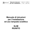
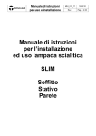
Instruction manual for use and installation MIU_010_GB 19/01/10 Rev.0 Page 1 of 31 Instruction manual for installation and use of scialytic lamp Pentaled12 Instruction manual for use and installation Introduction MIU_010_GB 19/01/10 Rev.0 Page 2 of 31 Dear installer, we ask you to read this manual carefully before installing the product. By doing so you will be able to protect yourselves and all the possible future users against any damage. Mark This apparatus is a Class I medical device in accordance with the European Directive on medical devices (MDD) 93/42/EEC, June 1993, Appendix 9 Conformity The manufacturer represents that this product complies with the essential requisites of the MDD Appendix 1 and proves such conformity by affixing the EC mark Manual’s validity This instruction manual for the installation of wall-anchor lamps is valid for the following models: Customer service Pentaled12 The customer service is at your disposal in case of any questions as to the device and its use, if you wish to order spare parts and for service and warranty reasons. Copyright TECNO-GAZ Strada Cavalli, 4 I-43038 Sala Baganza - Parma - Tél.: +39 – 0521 – 83.39.26 Fax: +39 – 0521 – 83.33.91 e_mail: [email protected] The contents of this Manual can be modified by Tecno-Gaz, without notice or further obligations, in order to include variations and improvements. Copy or translation of any part of this manual without written consent by Tecno-Gaz is forbidden. Modification rights reserved Tecno-Gaz reserves the right to modify, cancel or otherwise change the data contained in this documentation at any time and for any reason without notice since Tecno-Gaz is constantly searching for new solutions Instruction manual for use and installation MIU_010_GB 19/01/10 Rev.0 Page 3 of 31 for the development of the products. We therefore reserve the right and duty to make changes in the devices supplied in terms of form, equipment and technology. IMPORTANT Please find attached a warranty coupon to be filled in and sent back to Tecno-Gaz. Such coupon completes: the traceability of the medical device as required by the MDD the Cover on the Product the confirmation of the complete reading of the manual by the installer as a necessary and sufficient clause so that he/she is declared FIT for the installation of the equipment (having all the necessary information for the installation through this manual) Instruction manual for use and installation MIU_010_GB 19/01/10 Rev.0 Page 4 of 31 Manufacturer’s declaration of conformity CE The Company: TECNO-GAZ S.P.A. ubicata in Strada Cavalli n. 4 - CAP 43038 - Sala Baganza – Parma - ITALIA declares on its own responsibility that the Medical Illumination Device for surgical and diagnostic use: PENTALED 12 APPLICARE ETICHETTA constructed by TECNO-GAZ SPA, conforms to the Attachment VII of the 93/42 EEC Directive of June 14th 1993 and applied in Italy by the Legislative Decree N° 46 of February 24th 1997 and successive variances moreover, it is in conformity with the following safety regulation EN 60601-241. Classification with reference to article 9 and Attachment IX of the 93/42/CEE Directive DESCRIPTION: Non invasive Medical Device (Par.1 “Definition”, art.1, paragraph 1.2, attachment IX) Active Medical Device (art.1, paragraph 1.4, attachment IX) CLASS: I (Par.3 “Classification”, art.1, paragraph 1.1 Rule 1, attachment IX) Name: Paolo Bertozzi Position: Managing Director Sala Baganza, 18-07-2006 Instruction manual for use and installation MIU_010_GB 19/01/10 Rev.0 Page 5 of 31 Table of Contents 1 General information ................................................................... 7 1.1 User’s qualification ...................................................................... 7 1.2 Packaging, transport, storage and characteristics of the installation site…………………………………………………..…………………… 7 1.3 Graphic symbols used in this installation manual ............................ 8 1.4 Graphic symbols used on the package .......................................... 9 1.5 Other graphic symbols used on the device .................................... 9 1.6 Warranty .................................................................................. 10 2 Instructions for the device keeper ............................................ 12 2.1 Technical safety characteristics .................................................. 12 2.2 Personnel instruction obligation .................................................. 12 2.3 Warranty and responsibility ........................................................ 12 2.4 Structural changes or variations ................................................. 12 2.5 Disposal after use ..................................................................... 13 3 Mechanical and electrical arrangement of the site....................... 13 3.1 Mechanical arrangement of the site ............................................ 13 3.2 Electrical arrangement of the site ................................................ 16 4 Product installation .................................................................. 17 4.1 Ceiling version lamp installation .................................................. 17 4.2 Installation of the floor version lamp ............................................. 18 4.3 Electrical system connection ....................................................... 19 Instruction manual for use and installation MIU_010_GB 19/01/10 Rev.0 Page 6 of 31 4.4 First switch on............................................................................ 23 4.5 Installation check and scialytic lamp testing operations before use 22 5 Importance of personal safety .................................................. 22 5.1 Intended use............................................................................. 22 5.3 Technical safety conditions ......................................................... 22 5.4 Other safety conditions (secondary effects) ................................. 23 6 Lamp description and operation............................................... 23 6.1 Description of the device ............................................................ 23 6.2 Description of the operation ....................................................... 24 7 Cleaning and disinfection......................................................... 24 7.1 Cleaning the device ................................................................... 24 7.2 Disinfection............................................................................... 25 7.3 Sterilizing the handpieces .......................................................... 26 7.4 Yearly inspections by the keeper ................................................ 27 8 Adjustments ............................................................................. 27 8.1 Adjustment of the swing arm ...................................................... 27 8.2 Adjustment of the braking force .................................................. 27 8.3 Search for failure....................................................................... 28 8.4 Spare part list ........................................................................... 28 9 Technical data ............................................................................. 29 Notes .............................................................................................. 31 Instruction manual for use and installation MIU_010_GB 19/01/10 Rev.0 Page 7 of 31 1 General information 1.1 User’s qualification Personnel’s qualification The following scheme describes in chronological order the life of the scialytic lamp and the qualifications required by Tecno-Gaz: Installation Tecno-Gaz or Qualified Installer Use Qualified/authorized medical personnel Ordinary maintenance Tecno-Gaz or maintenance by the qualified technical body Extraordinary maint. Tecno-Gaz or Qualified Maintenance Technician Service Tecno-Gaz or Authorized Retailer Cleaning Duly trained personnel Demolition Tecno-Gaz, Qualified Installer or Maintenance Technician DANGER Tecno-Gaz refuses all responsibility for any damage to people or things deriving from the use of the product by non-qualified operators. By qualified Installer/Maintenance Technician we mean the person/s who has/have attended a course at Tecno-Gaz or read this manual carefully and, as confirmation thereof, the warranty coupon attached must have been sent back 1.2 Packaging, transport, storage and characteristics of the installation site Packaging 1 box containing a complete scialytic lamp with installation instruction manual and user’s manual. Transport Transport is carried out by any road haulage contractor as long as they respect the following characteristics: Temperature (°C): -15 / +60 Humidity: 10 / 75 % Atmospheric pressure (h/Pa): 500 / 1060 Storage The devices packaged must be stored (warehoused) in a dry place and at the following temperature: Temperature (°C): -15 / +60 Humidity: 10 / 75 % Atmospheric pressure (h/Pa): 500 / 1060 Installation site Instruction manual for use and installation MIU_010_GB 19/01/10 Rev.0 Page 8 of 31 The site appointed for the installation of the equipment must have the following characteristics: Temperature (°C): +10 / +40 Humidity: 30 / 75 % Atmospheric pressure (h/Pa): 700 / 1060 1.3 Graphic symbols used in this installation manual In these installation instructions and on the lamp important directions are marked by means of symbols and identifying words. Identifying words such as DANGER, WARNING or ATTENTION indicate the classification of the risk of damage. This is highlighted with various symbols. DANGER signals an immediately dangerous situation which might cause death or serious damage. WARNING signals a potentially dangerous situation which might cause death or serious damage. ATTENTION signals a potentially dangerous situation which might cause moderate or slight damage. The following triangular symbol coupled with a side explanation indicates which danger is being faced: Electric shock, Mechanical danger due to hanging masses (quick release of a suspension arm) Instruction manual for use and installation MIU_010_GB 19/01/10 Rev.0 Page 9 of 31 1.4 Graphic symbols used on the package The symbols present on the boxes of the packages are listed below: High side of the package Maximum number of packages stackable Breakable package Humidity-suffering package Do not overlap packages with pallet Weight of the package 1.5 Other graphic symbols used on the device The symbols present on the lamp are listed below: B-Type device. Indicates the level of protection against direct and indirect contact Graphic symbol proving the EC marking of the product Symbol indicating the manufacture date (month and year) Fuses used by the device Danger symbol: laser beam in class II Instruction manual for use and installation MIU_010_GB 19/01/10 Rev.0 Page 10 of 31 1.6 Warranty Cover on the product 1. The product is covered by guarantee for a period of 12 months, including electric parts. Starting date of the warranty 2. The warranty becomes effective from the lamp installation date at the customer’s premises exclusively if the installation is carried out by TecnoGaz personnel. In any other case the warranty becomes effective from the lamp dispatch date from Tecno-Gaz warehouse to the customer’s premises. Transport Document Date 3. In case of contention, the date specified on the “Transport Document” given with the goods is considered valid. Repairs 4. Repair or replacement, under guarantee, of a part is carried out for well-assessed manufacture reasons and at the unchallengeable discretion of Tecno-Gaz. The warranty does not include personnel’s travels, packaging and transport charges. Standard wear 5. The warranty does not include components subject to normal wear and tear (including but not limited to: halogen lamps, fuses, relays, bearings, etc.) Exclusion 6. The warranty does not include: - failure and faults due to improper installation; - failure or defects caused by carelessness, negligence, abnormal use of the device or other causes not attributable to the constructor; Replacement interventions due to presumed defects or convenient inspections. 7. The right to replace the whole Lamp is not acknowledged. 8. The warranty does not grant any indemnity for direct or indirect damage of any nature to people or things, due to the inefficiency of the lamp. Improper use 9. Tecno-Gaz can not be held responsible for failure or damage caused by improper use of the product, non-maintenance or neglect of the basic principles of good maintenance (negligence). Use stop 10. No indemnity is acknowledged for Lamp stop. Loss of warranty 11. The warranty is lost automatically if the lamp is tampered with, repaired or modified by the buyer or third parties not authorized by TecnoGaz. Instruction manual for use and installation MIU_010_GB 19/01/10 Rev.0 Page 11 of 31 Technical interventions 12. For the interventions, the buyer must apply to the retailer only or the service centers as recommended by Tecno-Gaz. Replacing components 13. The components replaced under guarantee must be returned to Tecno-Gaz carriage free. Non-return 14. The non-return implies the charge of the cost of the part to the applicant. Returns 15. Tecno-Gaz does not accept returns by final users. Repairs 16. The returns to Tecno-Gaz for repair must be managed by the retailer or the service center chosen by the final user according to the commercial procedure CM-P-003 called “MANAGEMENT OF REQUEST FOR RESTITUTION, REPAIRING, REPLACEMENT OF TECNO-GAZ EQUIPMENT AND CLIENT COMPLAINTS”. Authorization for returns 17. The returns to RIMSA must be documented and authorized as per internal procedures. Technical documents 18. The products returning to Tecno-Gaz must be attached with the return authorization documents and a document describing the failure. Return dispatch 19. All products under repair must be sent to Tecno-Gaz carriage free and suitably packaged (it is compulsory to use the original package). Non-responsibility 20. The constructor does not deem himself responsible for the safety, reliability and performance of the device if: - the installation, additions, settings, repairs are not carried out by people authorized in advance by Tecno-Gaz; - the electrical system of the installation site does not comply with the national laws and/or regulations in force for electrical systems in sites used as medical premises and similar norms; - the equipment is not used in accordance with the instructions for use. Instruction manual for use and installation MIU_010_GB 19/01/10 Rev.0 Page 12 of 31 2 Instructions for the device keeper 2.1 Technical safety characteristics Cleaning personnel The cleaning and disinfection operations of the scialytic lamp system described in Chapter 7 must be carried out exclusively by duly instructed cleaning personnel. Service personnel The control and maintenance operations described in Chapter 8 must be carried out exclusively by qualified service personnel. 2.2 Personnel instruction obligation Instructing the users Instruct the personnel following the instructions for use as regards the lamp control, cleaning and care operations. Such personnel must be instructed by the keeper according to what is specified in this manual. 2.3 Warranty and responsibility Tecno-Gaz refuses all responsibility for the unreliable working of the scialytic lamps in case: - the installation, the changes and the repairs are not carried out by a Tecno-Gaz service technician or personnel authorized by Tecno-Gaz, - the device is not used in accordance to its intended use, the norms and the instructions for use. 2.4 Structural changes or variations Arbitrary changes For safety reasons, all structural changes or variations made in the device on one’s own initiative are forbidden. In case of similar changes or transformations, the warranty of the producer for this device is annulled. This way the producer does not assure any warranty for damage or injuries caused by structural changes or variations made in the device on one’s own initiative or by the use of non-original spare parts. Use Tecno-Gaz Using spare parts not provided by Tecno-Gaz or its representatives original spare parts implies annulment of the warranty. only Instruction manual for use and installation MIU_010_GB 19/01/10 Rev.0 Page 13 of 31 2.5 Disposal after use Life end disposal The used device contains valuable materials which can be reused. Dispose of the used device respecting the environment and in accordance with the national waste disposal directives in force. 3 Mechanical and electrical arrangement of the site 3.1 Mechanical arrangement of the site NOTE The building and electrical arrangement works for the installation of the product are the responsibility of the Final Customer. DANGER The building slab arrangement works to install the product must be carried out in a solid and safe way according to the standards by qualified personnel. By qualified personnel we mean, including but not limited to, the following professionals: Building Engineer, Surveyor, Building Contractor, duly registered with the Professional Register. DANGER In case of improper drilling, e.g. drilling of a piece of iron of the reinforced concrete, the technician responsible for the construction will have to be informed for safety reasons, since the statics of the premises might be compromised. ATTENTION The ceiling must have a capacity of at least 300 Kg/m2 and a thickness of at least 250 mm. The installation site must be declared fit for use. After making sure that the site used as medical premises complies with the requisites required above, proceed to the mechanical anchorage of the ceiling plate determining the type of ceiling for the anchorage and acting accordingly. The installer assumes all responsibility, technical, civil and legal, related to the correct and suitable arrangement of the anchorage and installation of the product, which must be carried out according to the standards. Instruction manual for use and installation Fixing positions MIU_010_GB 19/01/10 Rev.0 Page 14 of 31 The scialytic lamp is supplied complete with tiges. Its length varies in relation to the height of the premises in which the lamp is to be installed. The tiges is calculated to install the lamp at a finished height from the floor to the head of the lamp with the oscillating arm in a horizontal position of about 190/200 cm, save a different request from the client. As a non-exhaustive example, we list some of the types of slab: Reinforced concrete Mechanical anchorage: fix the ceiling plate by means of 6 screw anchors Hilti HSL-3-G M8/20 following the directions given by the insert manufacturer scrupulously and listed below for information: Anchor tie-rod HSL-3-G M8/20 do (mm) t (mm) hs (mm) l (mm) Mt (Nm) SW (mm) x (mm) 12 80 60 98 25 13 20 do Nominal diameter of the point Mt t Minimum depth of drilling Sw Opening of the spanner hs Minimum depth of insertion l Length of anchor tie-rods x Closing torsion moment Fixing height Instruction manual for use and installation MIU_010_GB 19/01/10 Rev.0 Page 15 of 31 1. Using the paper template attached to this manual, mark all the 8 fixing holes of the chosen point of the ceiling. 2. Make the first hole according to the safety anchor diameter. 3. By means of a pump or vacuum cleaner with pipe terminal, remove the dust and the small drilling fragments from the hole. 4. The anchor tie-rod must be inserted into the hole keeping it to axis and using a hammer. Attention! Consider the insertion depth. 5. By the hexagonal dynamometrical spanner tighten with spanner adjusted at the value specified by the constructor of the anchors, opening the anchor. The anchor tie-rod will immediately take the weight. 6. Make the remaining 7 holes and insert the anchor tie-rods as in previous points 2– 5. 7. After one hour, tighten the anchor tie-rods again with the tightening torque prescribed. Chemical anchorage: fix the tiges with n° 8 chemical injection anchors mod. Hilti HIT-HY 150 with HAS following the directions given by the manufacturer Hilti scrupulously. After arranging the chemical anchors to the CEILING, fix the tiges with nuts and lock nuts for each tie-rod and tightening with the hexagonal dynamometrical spanner you will tighten with spanner adjusted at the value specified by the constructor of the anchors. Clay-cement mix Instruction manual for use and installation MIU_010_GB 19/01/10 Rev.0 Page 16 of 31 In this case it is compulsory to enclose the slab sandwich-like by the lamp plate and the counter-plate. Plate and counter-plate must be enclosed to each other with M8 steel threaded bars each, blocked at the upper and lower ends by respective washers, nuts and lock nuts. 3.2 Electrical arrangement of the site DANGER The electrical system arrangement works of the site used as medical premises to power the Product must be carried out in a safe way according to the standards by qualified personnel. By qualified personnel we mean, including but not limited to, the following professionals: Electro-technician licensed to practise as electrician DANGER Before installing the scialytic lamp check the following conditions: the electrical system of the installation site must comply with the national laws and/or regulations in force for electrical systems in sites used as medical premises and the national laws and/or regulations in force; the electrical system must be certified by an electrician licensed to issue the conformity certificate; the verification of the earthing must be certified as required by the norms in force. Upstream of the device, the plant must provide a magneto-thermic switch, sited on the line which distributes power to the lamp itself; this switch must have a distance between the contacts of at least 3 mm. Instruction manual for use and installation MIU_010_GB 19/01/10 Rev.0 Page 17 of 31 4 Product installation Before starting the installation make sure that no package is missing, in bad condition or damaged during transport and that the contents conform to what is specified above. Complaints will be considered only if the seller or the forwarder are warned immediately. Each complaint must be made in writing. Goods are always carried at the buyer’s risk. Keep the original package in case the lamp is to be returned. 4.1 Ceiling version lamp installation 4.1.1 Installation of ceiling plate, anchoring tube, power supply and covering ATTENTION Incorrect plate levelling may cause the horizontal arm of the lamp to make an undesired spontaneous move, when passing from the non-balance condition to the balance one. See drawing 52 Position the template sheet (drawing 51) (2) on the ceiling (1) fixing it with adhesive tape (3). Make the 8 holes following what is prescribed in paragraph 3.1 See drawing 53 After making the holes on the wall (1), fix the plate (2) to the ceiling by nuts and lock nuts (3). See drawing 54 Fix the anchoring tube (1) to the threaded pins of the ceiling plate (2) by nut and lock nut (3), ensuring the correct rod levelling by means of a spiritlevel (4). See drawing 55 The anchoring tube (1) is supplied with a standard size of 100cm. Using a jigsaw (2), cut the tube to the desired size in relation to the height of the room (cut the tube from the side (3) opposite to the one with the fixing holes (4) of the horizontal arm). To determine the correct length of the tube use the table given (the recommended height between floor and lamp head is 200cm). See drawing 56 Instruction manual for use and installation MIU_010_GB 19/01/10 Rev.0 Page 18 of 31 Insert the anchoring tube (1) down to beat into the ceiling plate hub (2) (keeping the cut side upwards); to lock it, tighten screw (3), the serrated washer (5) and the nut (4), thus exerting a hub pressing action and allowing the tube tightness. See drawing 57 By a drill (1), make a 7mm diameter hole on the tube side near the nut M8 (2) welded on the plate hub; then insert and screw the M8 conical-pointed dowel supplied in the nut (3) until its conical point presses against the hole previously obtained in the anchoring tube. WARNING – Lamp falling danger See drawing 58 Make sure that the lamp power supply cable (1) can reach the power supply board (2) of the lamp without creating interferences with the anchoring tube. Then position the cover (3) and the relevant locking ring (4). 4.1.2 Installation of the structure on the ceiling tube See drawing 59 Insert the connection cables (7) along the anchoring tube making them out from the tiges plate so they can reach the connection terminals of the electrical panel. Align the horizontal arm pin (3) with the anchoring tube (4). Connect the connectors (1) and (2). Insert the pin into the tube fitting in the relevant fixing holes, and fix it screwing in the four screws (5) using a hexagonal wrench (6). 4.2 Installation of the floor version lamp 4.2.1 Installation of stand, power supply and covering See drawing 60 Remove the bolt (2) from the stand bottom (1). Mechanical connection Position the stand (1) on the base (5) fitting and inserting its pawl (6) into the plate seat (7), use the bolt previously unscrewed to join the stand to the base and tighten thoroughly. Insert the cover (3) from the stand top and the relevant connecting clip (4). Instruction manual for use and installation MIU_010_GB 19/01/10 Rev.0 Page 19 of 31 WARNING – Instability and falling danger Failure to insert the detent into the appropriate seat present on the basement plate implies the risk of instability and the possible fall of the structure. 4.2.2 Installation of heeling arm and head See drawing 61 Align the heeling arm pin (8) with the floor stand (1). After connecting the electric cable terminals (9) to (10) each other, insert the heeling arm pin into the stand fitting in the holes (11) with those of the stand (12) and screw in the two locking screws (13) by a screwdriver. 4.3 Electrical system connection WARNING – Electric shock Before connecting, make sure that the electrical system line is NOT under tension. The lamp power supply group (support sheet, feeder, terminal board) is firmly fixed to the plate of the anchoring tube or the base, in case of a ceiling version or floor version device respectively. As regards the connection of the electrical system line (F,N) and the lamp cables (+,-,T) follow what is specified in the specific wiring diagram attached. Fuses The device fuse protection is ensured by installing, on the input line (F,N), two fuses type: 5x20 T.1A See drawing 62 As for floor versions it is necessary to connect wires by the electric panel of the device; to do it, lift the connecting ring (1) and the cover (2). Now connect the connectors (3) (4) and (5) (6). Then reinstall the cover and the connecting ring and fix the cover by a screwdriver (7) tightening the screw M4 (8) and gripping inside the threaded bush (9) present on the electric panel support. Instruction manual for use and installation MIU_010_GB 19/01/10 Rev.0 Page 20 of 31 WARNING – Irreparable damage to the device In the case of ceiling versions, the fuse protection to the electric panel terminals must be inserted ONLY AFTER completing the mechanical and electrical assembly of the lamp. Advance insertion may cause irreparable damage to the light source. If the product is not used for long periods, remove the fuses. 4.4 First switch on Before supplying the lamp with voltage, remove the protection film from the head screen surface and from the floor base cover. ATTENTION Now it is possible to power the lamp to make sure it gives out light. To do so you must: 1 – close the system circuit by means of the head system switch (customer’s responsibility) 2 – press the green switch on the base cover (floor version) 3 – press the I/O keyboard Instruction manual for use and installation MIU_010_GB 19/01/10 Rev.0 Page 21 of 31 4.5 Installation check and scialytic lamp testing operations before use ATTENTION The following notes are to be considered compulsory during the installation check as they prove the correct verification of all the points set out. For such reason every single point must be ticked when it is treated. 1. Make sure the ceiling is suitable for installing the lamp 2. By means of a spirit-level, make sure the anchoring tube is perpendicular 3. Make sure the bolt is well tightened on the locking clip 4. Check the hole and make sure the safety dowel is inserted on the anchoring tube 5. Make sure the 4 screws M4 supporting the horizontal arm (ceiling version) are well tightened 6. Make sure the floor stand pawl is properly inserted into the relevant base seat 7. Check the device earthing and make sure the earthing terminals are well tightened 8. Make sure the movement mechanism works perfectly. Check the mechanical operation of the lamp by directing and rotating it and make sure that all movements are frictioned so that the lamp is stable in any position and does not lose its position 9. After turning on the lamp, it must give out light from the head Seal and signature of the installer: ___________________________________________________________ Instruction manual for use and installation MIU_010_GB 19/01/10 Rev.0 Page 22 of 31 5 Importance of personal safety 5.1 Intended use Use compling with the norms The PENTALED 12 scialytic lamp is used to light the area of the patient undergoing a surgical operation or an examination and intended to be used in operating rooms or medical clinics. Work field The work field is a distance from about 70 to 140 cm from the operation point. Single lamp (minor surgical luminaire): Definition In accordance with EN60601-2-41, a PENTALED 12 single lamp is a minor surgical luminaire and can be used only on operations where the interruption of the lighting does not cause any risks for the patient. 5.2 Environmental conditions - The PENTALED 12 scialytic lamp system is not suitable for the use in explosion-risky areas. - The PENTALED 12 scialytic lamp system is not suitable for the use in the presence of inflammable mixtures of anesthetics with air, oxygen or NO2 (laughing gas). - During working, the room temperature must be between 10°C and 40°C. - The relevant humidity must be between 30% and 75%. - The atmospheric pressure must be between 700 and 1060hPa. 5.3 Technical safety conditions The safe use and proper working of the PENTALED 12 lamp is guaranteed if: Safe anchorage anchorage of the lamp to the ceiling/wall is safe from the static point of view and Systems there is a static stability test, the electrical systems of the sites concerned comply with the local norms in force, Authorized personnel changes or maintenance of the lamp are made by Tecno-Gaz authorized personnel, Instruction manual for use and installation MIU_010_GB 19/01/10 Rev.0 Page 23 of 31 Proper installation the lamp has been installed following the currently valid installation and commissioning instructions and has been commissioned regularly by the authorized installer, Original spare parts Tecno-Gaz original parts only are used for service, repair and structural variation operations and as accessories. 5.4 Other safety conditions (secondary effects) Dazzling Do not look frontally inside the lamp when it is on and do not insert reflecting objects into the path of the rays. Considering the high lighting power, there is strong dazzling danger. Improper use Do not lay any object on the body of the lamp or hang objects on the arm or the body of the lamp, since a safe positioning is no longer ensured and suc objects may fall on the operation area. The load of heavy objects (body weight of a human being) can damage the mechanics. Cover the heads During working the head of the lamp must not be covered since it would prevent the thermal exchange with the environment and cause overheating of the lamp. Collisions Collisions of the mobile arms and the lamp body must be avoided. In case of violent collision, the lamps may be damaged or pieces of paint may chip and fall on the operating field in the patient area. 6 Lamp description and operation 6.1 Description of the device Versions See drawing 63 The PENTALED 12 scialytic lamp is available in the following versions: - floor - ceiling FLOOR version: wheel base (1), stand (2), stand extension (3), heeling arm (4), lamp head (5), function control keyboard (6), sterilizable handle (7), power supply plug (8). See drawing 64 CEILING version: ceiling anchoring tube (1), ceiling cover (2), horizontal arm (3), heeling arm (4), lamp head (5), control keyboard (6), sterilizable handle (7). Instruction manual for use and installation MIU_010_GB 19/01/10 Rev.0 Page 24 of 31 6.2 Description of the operation Pannello di comando The function control keyboard is applied to the scialytic lamp head. Such keyboard allows to turn the lamp on and off by means of the membrane key I/O (1), to regulate the light intensity by pressing the keys with the symbols ‘+’ (2) and ‘-‘ (3), and display the level of intensity reached through 3 green position micro-LEDs (4). 1 4 3 2 Light field The light field is fixed and therefore any adjustment of its diameter dimension is prevented. 7 Cleaning and disinfection 7.1 Cleaning the device WARNING – Electric shock danger Turn off the lamp by the master switch of the operating room and make sure it does not turn on again; in the case of floor versions remove the power supply plug from the electric system socket, protect the device against water sprinkling and do not clean/disinfect it with liquids. Instruction manual for use and installation MIU_010_GB 19/01/10 Rev.0 Page 25 of 31 Clean with alcohol, low-alkaline and chlorine-less detergent. ATTENTION Do not use abrasive products, petrol, paint thinners, alkaline detergents, acids; proportion the detergents so that so that no liquids seep into the lamp bodies and the support arm system. Clean the lamp with a damp but not wet cloth. 7.2 Disinfection WARNING – Electric shock danger Turn off the lamp by the master switch of the operating room and make sure it does not turn on again; in the case of floor versions remove the power supply plug from the electric system socket, protect the device against water sprinkling and do not clean/disinfect it with liquids. Let the lamp body cool down. Disinfect the lamp body only when it is cold. Use alcohol or aldehyde-based products. WARNING Disinfectants may contain substances harmful to the health: use disinfectants only respecting the health standards fixed by the hospital, the device keeper must respect the requisites imposed by the national competent hygiene and disinfection commission. ATTENTION To avoid damage to stainless steel, aluminum parts, only use disinfectants with no chlorine or halogens, to prevent plastic parts from becoming fragile, only use low-alcohol disinfectants, proportion the detergents so that so that no liquids seep into the lamp bodies and the support arm system. Clean the lamp with a damp but not wet cloth. Instruction manual for use and installation MIU_010_GB 19/01/10 Rev.0 Page 26 of 31 7.3 Sterilizing the handpieces WARNING – Danger for the patient Replace the handpieces as soon as they show cracks or deformations, since they might fall on the area of the wound. The lamp keeper must respect the requisites imposed by the national competent hygiene and disinfection commission. Installation / uninstallation of the handpiece: - press the two lateral safety keys of the handpiece and extract the handpiece itself. - insert the handpiece till the bottom until the safety keys don’t fall in their seats. Cleaning, disinfection and sterilization of the handpiece the handpieces are made of plastic material resistant to heat and collisions (PSU). They can be cleaned with a detergent having medium alkaline level but no active chlorine. To disinfect the handpieces we recommend to use alcohol or aldehydebased products. The disinfectants must be approved by the manufacturer for use on the polysulfone (PSU). Before sterilizing, rinse the handpieces. The handpieces can bear about 300 steam sterilization cycles if the following instructions are respected: - steam sterilization at a121°C 1,3bar from 25 to 30 minutes, or - steam sterilization at a134°C 2,3bar 4 minutes. Put the handpieces upright with downward open side. Do not exceed the sterilization temperature of 134°C. Avoid contact of the handpieces with other objects when disinfecting. Each device, in time, is subject to some wear and tear. The safety and working of the device must then be checked in the inspection and maintenance intervals. Instruction manual for use and installation MIU_010_GB 19/01/10 Rev.0 Page 27 of 31 7.4 Yearly inspections by the keeper ATTENTION Respect the yearly inspection intervals and check the device as follows: - damage to the painting with danger in case of open wounds - cracks on the plastic part - detachment of parts - integrity of the earthing circuit 8 Adjustments 8.1 Adjustment of the swing arm See drawing 65 The lamp is supplied already balanced and needs no further adjustment. If, in time, the spring balancing swing arm stiffens or loosens, it is possible to intervene mechanically adjusting the compression of the internal spring. Slide the rubber grommet forward (1) and the cover (2) along the heeling arm (3). Insert a pin (4) having maximum diameter of 4mm into the holes of the ring nut (5) and rotate in the directions of the arrows to increase/decrease the charge of the spring. If the heeling arm lowers, the elastic force of the spring is insufficient: - rotate the lever downwards to charge the spring. If the heeling arm still goes up, the elastic force of the spring is too high: - rotate the lever upwards to discharge the spring. At the end of the adjustment, put the cover back to its original position. 8.2 Adjustment of the braking force See drawing 65 As for all the mechanic parts, brakes also are subject to wear and tear. If the lamp body does not automatically keep the position it is put to, it is necessary to adjust the braking force by acting on the screws of the brakes. Horizontal arm brakes Use a 2.5 hexagonal wrench (7) to increase the braking force, rotating the arm brake dowels (6) clockwise. Instruction manual for use and installation MIU_010_GB 19/01/10 Rev.0 Page 28 of 31 8.3 Search for failure n Problem The lamp does not keep the position 1 Solution Check the leveling of the plate installed on the wall (wall), of the shank to the base (floor), of the pipe anchored to the ceiling (ceiling) Tighten the brakes to the articulations in order to increase the frictions. 2 The lamp does not work Check the presence of the fuses inside the terminal box (T1A), the hooking of the electrical connectors. Check the presence of voltage in the lamp head 3 The fuse keeps burning Check the characteristics of the fuses inserted 4 The lamp flickers Contact the service center 5 The light beam on the operating field is not on focus (faulty meeting of the light fields through handle rotation) Contact the service center. 6 The lamp does not turn on. Check the power supply voltage and fuses. Electronics are damaged: contact the service center 8.4 Spare part list Description Order code Sterilizable handle Z180045 Electronic card PENTALED 12 Z300617 Membrane keyboard Z300220 Instruction manual for use and installation MIU_010_GB 19/01/10 Rev.0 Page 29 of 31 9 Technical data Technical data on light Illumination Ec at a distance of 1 m [Lux] ±10% PENTALED 9-FF 50.000 Color temperature [K] ±5% 5.000 K (±5%) Color rendering index Ra [-] 94 Diameter of the light field d50 [mm] 85 Diameter of the light field d10 [mm] 140 Illumination depth [mm] 1500 Maximum irradiation [W/m2] 119 Irradiation / Illumination [mW/m2lx] 2,38 Maximum irradiation in the UV [W/m2] 0,001 Focus by handle No Data on electrical connection Primary alternating voltage [Volt ac] Frequency [Hz] 100÷240 50/60 Absorbed power [VA] 40 Light source N°12 Led x 2W LED light source duration [h] (this datum can vary according to voltage peaks and the frequency of use) Light intensity control 50.000 50 - 100 General data Color RAL 9003 Directive 93/42 EEC Standard EN 60601-2-41 Instruction manual for use and installation MIU_010_GB 19/01/10 Rev.0 Page 30 of 31 Electrical safety class Class I Protection against direct and indirect contacts B-type device Dimensions Lamp body diameter [cm] 30 Diameter of the poly-elliptical reflector [cm] 5,5 Light emission surface [cm2] 285 Scialytic wall, mobile, ceiling lamp weight [Kg] 18; 13 Certificates Complying with directive 93/42/EEC Instruction manual for use and installation Notes MIU_010_GB 19/01/10 Rev.0 Page 31 of 31