1
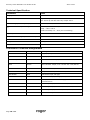
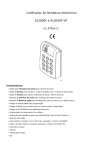
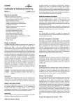
Electronic Code Lock
SL2000E v1.2
Rev.A
Features
·
Door Relay output
·
Status transistor output
·
Aux transistor output
·
Door Contact input
·
Exit Button input
·
INSTALLER code for programming
·
MASTER code for arming/disarming
·
USER codes for door opening
·
Door Alarm indication
·
Option: Timed Lock-out after three wrong codes
·
Option: Access only when Disarmed
·
Programmable length of codes
·
User indexing for easy administration of codes
·
Nonvolatile memory
·
Keypad with backlight
·
Door Bell key
·
Three LEDs and buzzer
·
Tamper contacts
·
Outdoor operation (IP65)
Security Locks SL2000E v1.2 EN Rev.A.doc
2011-09-01
Introduction
The SL2000E electronic code lock is designed for operation as a indoor/outdoor stand-alone door access control
unit. The device is equipped with one relay output, two transistor outputs and two NO inputs. All codes and
parameters configuring the device’s operation are stored in nonvolatile memory.
Functional Description
Note: The C1,C2…C10 parameters which appear in this manual refer to configuration settings programmed to
the SL2000 during Memory Reset procedure (see section: Configuring the SL2000 later in this document).
Door Relay Output
This output is designed to control a door locking device (e.g. door strike or magnetic lock). Each time the valid
USER code is entered the SL2000 starts counting time delay specified by C1C2 parameters and after it elapses
the relay output is activated for a time defined by C3C4 value. The triggering of the Door Relay output is
indicated by LED OPEN (green), this LED lights up as long as Door Relay output is on.
Note: If the option Disable Access in Armed Mode is enabled the activation of the Door Relay output may occur
only when the unit operates in the Disarmed mode.
Status Output
When the SL2000 is in Armed mode this output is not active and remains in high resistance condition. When
code lock switches to Disarmed mode the Status output shorts to supply minus (GND) and stay in this condition
as long as the SL2000 operates in the Disarmed mode. The maximum current sink by this output is internally
limited to 1.0A, the maximum voltage applied to it must not exceed 16V DC. The Status output can be used for
rearming of an alarm zone or to control any other device or system which requires on/off method of control.
Note: The arming and disarming of a code lock can be carried out by MASTER code only.
Aux Output
Normally this output remains in high resistance state, if triggered it shorts to supply minus (GND). The Aux
output has been designed to indicate two situations:
·
Door Bell event
·
Door Alarm event
Whenever the Bell key is pressed for a moment or the [#] key is pressed and held down longer then half a
second, the Aux output goes steady on (shorts to supply minus), the Aux output remains in this condition as
long as the Bell or [#] key is being pressed.
The Aux output can be also activated when Door Alarm is active. The code lock indicates the Door Alarm
through pulsed modulation of the Aux output. Thanks to this feature (steady or pulsed output) operator may
distinguish the Bell signal from the Door Alarm.
The maximum current sink by this output is internally limited to 1.0A, the maximum voltage applied to it must
not exceed 24V DC. Normally the Aux output is used to trigger some kind of warning device (e.g. alarm siren or
buzzer).
Note: The Door Alarm has higher priority then the Door Bell event. As a result when two of those events occur
simultaneously only the Door Alarm is indicated on the output line.
Exit Button Input
Triggering of this input activates Door Relay output on the same rules as the entry of a valid USER code. The
Exit Button is a NO type – it becomes triggered when shorted to supply minus (GND).
Door Contact Input
This input is dedicated for a connection of a door open sensor. When input is open or left unconnected the code
lock assumes that door is closed, when input is shorted to supply minus (GND) the SL2000 assumes that door
is open.
Page 2 of 11
Security Locks SL2000E v1.2 EN Rev.A.doc
2011-09-01
Note: If you are not going to use a door open sensor leave the Door Contact input unconnected. Without a door
open sensor the SL2000 will not indicate the Door Open alarm.
LED System Input
This input is dedicated to control the LED SYSTEM (orange), shorting this input with supply minus lights up LED
SYSTEM. The LED SYSTEM can be use to any purpose required by installer (e.g. to indicate actual status of the
alarm system).
Door Open Alarm
The Door Open alarm will occur when:
·
door has been opened without entering of a valid USER code
·
door has been opened without pressing of the Exit Button
·
door has not been closed within C5C6 time from the moment when door locking device was deactivated
The Door Open alarm is indicated by pulsed activation of the Aux output which is accompanied by a continues
acoustic signal generated by the internal buzzer. Pressing any key will cease the acoustic signal – however this
does not cancel the alarm indication on Aux output. The indication on the Aux output disappears when door
becomes closed or automatically after 60 seconds from the moment when alarm arose.
Option 1: Timed Lock-out
If this option is enabled the lock disables the keypad for 60 seconds after three attempts of entry of incorrect
code. After this time the SL2000 re-enables the keypad and is ready to accept new keypad’s entries. The end of
60 seconds lock-out time is indicated by two series of two beeps (** **).
Option 2: Disable Access in Armed mode
If this option is enabled the SL2000 grants access to a room only when it operates in Disarmed mode. With
this option active the access to the controlled door will be disabled for both all USER codes and Exit Button
unless the SL2000 will be switched to Disarmed mode.
Note: Thanks to this option the MASTER user can disable access to the room by switching the unit to Armed
mode and vice verso, he can enable access to controlled door by switching the code lock to Disarmed mode.
The SL2000 can be switched between Armed and Disarmed modes through the MASTER code only.
Arming and Disarming of the Code Lock
In normal operation mode the SL2000 may work either in the Armed or Disarmed mode. The Armed mode is
signalled by LED ARMED (red) whereas the Disarmed mode is signalled by LED DISARMED (green). The actual
operating mode of a lock is also indicated on the Status output line which when active indicates that unit is
Disarmed. The switching between Armed and Disarmed modes can be carried out by MASTER code only.
Whenever code lock switches to Disarmed mode is generates two series of two beeps (** **) whereas when
switches to Armed mode it generates two beeps (**) only.
Codes
The SL2000 offers three types of codes:
·
MASTER Code
·
INSTALLER Code
·
USER Codes
Each type of code is designed for individual purpose. The length of each code can be programmed during
Memory Reset procedure. The entry of each code must be followed by the [#] key which is used to mark the
end of a code.
MASTER Code
The MASTER code is used to switch the SL2000 between Armed and Disarmed modes, it can be 4-10 digits
long.
INSTALLER Code
The INSTALLER code is required to enter the Installer Programming mode, it can be 4-10 digits long.
Page 3 of 11
Security Locks SL2000E v1.2 EN Rev.A.doc
2011-09-01
USER Codes
These codes are used for activation of the Door Relay output. Each time a valid USER code is entered the
SL2000 starts counting C1C2 time delay and then when it passes by the unit activates Door Relay output. The
Door Relay output is activated for time defined by C3C4 settings. The USER codes can be 2-8 digits long.
Note: The SL2000 enables programming of maximum 55 USER codes, each of them can open the door.
Commands
Commands can be entered during normal working time of a SL2000 code lock and doesn’t require entry to the
programming mode.
[USER Code] [#]
Whenever a valid USER code is entered the code lock generates two beeps (**) and then starts count C1C2
time delay. After it passes by the SL2000 activates Door Relay output for time defined by C3C4 settings. During
this time door locking device is energized and user can open the door.
[MASTER Code] [#]
Each time the MASTER code is entered the SL2000 changes its arming mode (switches from Armed to Disarmed
mode or in reverse direction).
[INSTALLER Code] [#]
After this command code lock generates two beeps (**) and enters the Installer Programming mode. In this
mode installer can program the USER codes to a unit.
[*] [Old INSTALLER Code] [#] [New INSTALLER Code] [#]
This command erases the old INSTALLER code and program new INSTALLER code. If command is successfully
accomplished the unit generates three series of two beeps (** ** **).
[*] [Old MASTER Code [#][New MASTER Code] [#]
This command erases the old MASTER code and program new MASTER code. If command is successfully
accomplished the unit generates three series of two beeps (** ** **).
Note: Whenever you re-program MASTER or INSTALLER code remember that new code programmed into a unit
must have the same length as the old one.
[Bell Key]
A single short press of this key activates the Aux output and internal buzzer for a time of ~2…3 seconds. The
indication on Aux output and buzzer is continued for entire time as long as Bell key is being pressed.
[#]
Normally it marks the end of a code but when pressed separately for a time longer the 0.5s it acts in the same
way as Bell key.
Programming of the USER Codes
The SL2000 enables programming of up to 55 different USER codes. The USER codes can be managed
(added/deleted/changed) only in the Installer Programming mode. In order to program the USER codes you
must first enter the Installer Programming mode and the you have access to the programming commands listed
below:
[0] [1] [#] [code] [#]
- Programming of the USER code no. 1
[0] [2] [#] [code] [#]
- Programming of the USER code no. 2
[0] [3] [#] [code] [#]
- Programming of the USER code no. 3
...etc.
...etc.
...etc.
[5] [5] [#] [code] [#]
- Programming of the USER code no. 55
[0] [0] [#]
- Delete all USER codes
[9] [9] [#] [code] [#]
- Deletes the code entered in square brackets
Page 4 of 11
Security Locks SL2000E v1.2 EN Rev.A.doc
[#]
2011-09-01
- Exit from the Installer Programming mode
When the code lock accepts the new USER code it generates two series of two beeps (** **). Any attempt to
program a USER code which already exists in memory or to program it with a code length bigger then
programmed during Memory Reset will cause the programming error signalled by the long acoustic beep.
Configuring the SL2000 ( Memory Reset)
In order to configure the SL2000 you must perform the Memory Reset and then enter sequentially 10 digits
(called C1-C10) which will configure the unit for individual installation. After the Memory Reset the entire
contents of the code lock memory is erased (including all codes) and initialized with Default (Factory) settings.
These values
In order to perform Memory Reset do the following steps:
·
Turn off the power supply
·
Connect Reset wire (Brown-Yellow) to supply plus
·
Turn on the power supply
·
Wait till the moment when device will sound three series of two beeps (** ** **) - this signal indicates that
SL2000 erased memory and restored default configuration settings
·
Disconnect Reset wire (Brown-Yellow) from supply plus
·
Enter sequentially ten digits C1-C10
·
After the last digit is entered the code lock generates the three series of two beeps (** ** **) then ends
the Memory Reset procedure and switches to normal working mode.
Meaning of the configuration parameters: C1-C10
C1C2: Open Delay, specifies the time delay from a moment when access is granted to a moment when Door
Relay will be activated. It can be programmed from 00 to 99s (default: 04).
C3C4: Lock Activation Time, specifies the time for which Door Relay will be activated when access is granted.
It can be programmed from 00 to 99s (default: 04).
C5C6: Time for Door Closing, specifies the time within which door must be closed. It can be programmed from
00 to 99s, the 00 value sets unlimited time for closing (default: 09).
C7: Enables or disables of reprogramming of the MASTER and INSTALLER codes, enter 0-3 (default: 0).
Value
Reprogramming of the MASTER code
Reprogramming of the INSTALLER code
0
Enabled
Enabled
1
Disabled
Enabled
2
Enabled
Disabled
3
Disabled
Disabled
Note: If reprogramming of a given code is disabled the SL2000 allows you a single attempt only to program of
the given code. Once the code is programmed, you will not be able to change it unless the Memory Reset is
carried out. Use this function to disable the end user to change your MASTER and INSTALLER code
C8:
Enabling and disabling Option 1 and Option 2, enter 0-3 (default:0).
Value
Option 1
Option 2
0
Disabled
Disabled
1
Enabled
Disabled
2
Disabled
Enabled
3
Enabled
Enabled
Option 1: Timed Lock-out
Page 5 of 11
Security Locks SL2000E v1.2 EN Rev.A.doc
2011-09-01
Option 2: Disable USER Codes When in Armed Mode
C9:
Defines the length of the USER codes, enter 0-3, (default: 1).
C10:
0:
USER codes are 2 digits long
1:
USER codes are 4 digits long
2:
USER codes are 6 digits long
3:
USER codes are 8 digits long
Defines the length of the MASTER and INSTALLER codes, enter 0-3, (default: 1).
0:
Both codes are 4 digits long
1:
Both codes are 6 digits long
2:
Both codes are 8 digits long
3:
Both codes are 10 digits long
If an illegal operation occur during Memory Reset the device will signal an error (long beep) and will return to
the beginning of the programming so you can start to enter the C1-C10 digits once again. The Memory Reset
procedure automatically comes to an end when the last (C10) digit is entered. The device stores the
configuration as well as all codes in a nonvolatile memory which can be reprogrammed whenever required.
After the Memory Reset procedure comes to an end all codes are set to default values (see section Default
Codes).
Example:
The following digits C1-C10 were entered during the Memory Reset procedure: [0][1][0][2][3][3][1][0][2][3]
This sequence sets the following options:
·
Open Delay: 01 second
·
Lock Activation Time: 02 seconds
·
Time for Door Closing: 33 seconds
·
Reprogramming of the MASTER code: disabled
·
Reprogramming of the INSTALLER code: enabled
·
Option 1; Timed Lock-out : option off
·
Option 2; Disable Access in Armed Mode: option off
·
USER codes: 6 digits
·
MASTER and INSTALLER codes: 10 digits
Default Codes
After the Memory Reset is accomplished the following codes are automatically programmed into a unit:
MASTER Code
All digits are “1” (1111…), the length of the code depends on the C10 parameter entered during Memory Reset
procedure.
INSTALLER Code
All digits are “2” (2222…), the length of the code depends on the C10 parameter entered during Memory Reset
procedure.
USER Code no 01
All digits are “3” (3333…), the length of the code depends on the C9 parameter entered during Memory Reset
procedure.
USER Code 02..55
All USER codes no 02 -55 are blank (they doesn’t exist).
Page 6 of 11
Security Locks SL2000E v1.2 EN Rev.A.doc
2011-09-01
Installation
·
The SL2000 code lock should be mounted near the supervised door on a vertical piece of supporting
structure.
·
Assure that the surface beneath of the controller’s rear panel is flat and smooth.
·
Disconnect power supply before making any electrical connections.
·
Once installed and electrically connected, the unit has to be properly programmed.
·
When forgotten, MASTER and INSTALLER codes can be reprogrammed through Memory Reset procedure.
·
The code lock must be supplied form reliable power supply, calculate the adequate wire gauge to guarantee
that the voltage dropout between the power supply and the DC input of SL2000 will not exceed 1V in the
worst case.
·
It is recommended to supply door release device (e.g. door strike or magnet lock) and SL2000 from
separate power supply but when both code lock and door release device are supplied from the same power
source you must use separate pairs of cable to supply each of them.
·
Always add the silicon diode (e.g. 1N400x series) in parallel to door release device – locate diode as close
as possible to door release and as far as possible from the code lock.
·
It is forbidden to supply the door release device directly from the DC input terminals of a code lock.
·
Do not attempt to use Door Relay output for switching of a voltages higher then 24V DC/AC.
Page 7 of 11
Security Locks SL2000E v1.2 EN Rev.A.doc
Page 8 of 11
2011-09-01
Security Locks SL2000E v1.2 EN Rev.A.doc
Page 9 of 11
2011-09-01
Security Locks SL2000E v1.2 EN Rev.A.doc
2011-09-01
Technical Specification
Parameter
Value
Supply
10...16 VDC
Current consumption
Avg. 25 mA @ 12V DC,
Max. 80 mA @ 16V DC with relay output active
Anti-sabotage protection (Tamper)
NC contact, 50mA/24V
Environmental Class (according to EN 501311)
Class IV, Outdoor-General,
Temp.: -25°C +60°C
Relative humidity: 10 - 95% (non-condensing)
Ingress protection
IP65
Connection cable length (for SL2000F-VP)
45cm
Dimensions
100 X 40 X 25
Weight
~ 150g
Approvals
CE
Connection Terminals Assignments
Label
Wire colour
Description
+12V
Red
Supply input plus
GND
Black
Supply input minus
Status Output
Green
Status transistor output, max. current sink 1.0A/16V DC
AUX
Brown
Aux transistor output, max. current sink 1.0A/16V DC
TMP A
Grey
Tamper contact A, NC max. 50mA/24V
TMP B
Yellow
Tamper contact B, NC max. 50mA/24V
Exit Button
Blue
Exit Button input, NO type
Door Contact
White-Green
Door Contact input, NO type, 1.5A/24V DC/AC
LED SYSTEM
Pink
NO input, when shorted with supply minus LED SYSTEM
becomes active
COMM
White
Door Relay output, COMMON contact, 1.5A/24V DC/AC
NO
Violet
Door Relay output, NO contact, 1.5A/24V DC/AC
NC
Grey-Pink
Door Relay output, NO contact, 1.5A/24V DC/AC
Reset
Brown-Yellow
User for memory reset
Page 10 of 11
Security Locks SL2000E v1.2 EN Rev.A.doc
2011-09-01
Ordering Information
Item
Description
SL2000F
Dark grey plastic enclosure, screw connection terminals, indoor installation only
SL2000F-VP
Vandal proof, metal front cover and keys, silver color, pig tail connection cable,
outdoor installation available
Product History
Version
Firmware
Date
Description
SL2000F v1.0
N/A
16/11/2009
Initial release of the product
SL2000F-VP v1.0
N/A
16/11/2009
Initial release of the product
The symbol of a crossed-through waste bin on wheels means that the product must be
disposed of at a separate collection point. This also applies to the product and all
accessories marked with this symbol. Products labeled as such must not be disposed of
with normal household waste, but should be taken to a collection point for recycling
electrical and electronic equipment. Recycling helps to reduce the consumption of raw
materials, thus protecting the environment.
Contact
Roger sp. j.
82-400 Sztum
Gosciszewo 59
Tel.: +48 55 272 01 32
Fax: +48 55 272 01 33
Technical support PSTN: +48 55 267 01 26
Technical support GSM: +48 664 294 087
e-mail: [email protected]
Page 11 of 11