1
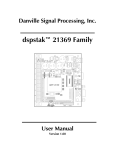
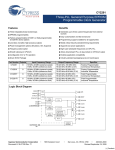
Danville Signal Processing, Inc.
dspstak™ Family
User Manual
Version 2.00
Danville Signal Processing, Inc.
dspstak™ Family User Manual
Copyright © 2004 Danville Signal Processing, Inc. All rights reserved. Printed in the USA.
Under the copyright laws, this manual may not be reproduced in any form without prior written
permission from Danville Signal Processing, Inc.
Danville Signal Processing, Inc. strives to deliver the best product to our customers. As part of this
goal, we are constantly trying to improve our products. Danville Signal Processing, Inc., therefore,
reserves the right to make changes to product specification or documentation without prior notice.
Updated operating manuals and product specification sheets are available at our website for
downloading.
This manual may contain errors, omissions or “typo’s”. Please send your comments, suggestions and
corrections to:
Danville Signal Processing, Inc.
38570 100th Avenue
Cannon Falls, MN 55009-5534
Trademark Notice
dspstak is a trademark of Danville Signal Processing, Inc. VisualDSP++, EZ-Kit and SHARC are
trademarks of Analog Devices, Inc. CyberClocks is a trademark of Cypress Semiconductor
Corporation.
Contact Information
Danville Signal Processing, Inc.
38570 100th Avenue
Cannon Falls, MN 55009
E-mail:
Web Site:
[email protected]
http://www.danvillesignal.com
Voice:
Fax:
507-263-5854
877-230-5629
dspstak™ Family User Manual
Page 2
Table of Contents
Overview ....................................................................................4
Introducing dspstak™.............................................................................4
dspstak™ Family & History.....................................................................4
Intended Audience ................................................................................5
Hardware & Mounting Configurations.......................................6
dspstak™ DSP Engine Standard Features...................................7
Power Supply ........................................................................................7
RS-232 Interface ....................................................................................8
USB Interface.........................................................................................8
Interconnect Port ...................................................................................8
Programmable Clocks ............................................................................9
JTAG Emulation Port ..............................................................................9
dspstak™ Interconnect Port .....................................................10
Connectors ..........................................................................................10
Connections ........................................................................................10
Signal Descriptions...............................................................................12
dspstak™ I/O Modules .............................................................14
SPI Port Connections ...........................................................................14
Mechanical Dimensions – DSP Module ...................................15
Mechanical Dimensions – I/O Module ....................................16
dspstak™ Family User Manual
Page 3
Overview
DSP-based embedded applications often take the form of a digital signal processing engine coupled
with a specialized data conversion and signal conditioning front end. The front end electronics and
the DSP are almost always connected via high speed serial ports and the general purpose I/O ports
of the DSP. In most cases, once the local memory and peripheral interfacing needs of the DSP are
fulfilled, the DSP’s data and address busses are no longer needed.
Standardized bus architectures such as PC/104, PCI and cPCI are all based on communicating via
each board’s data and address bus, while ignoring the needs of the most DSP / data conversion
interfaces.
Introducing dspstak™
Danville’s dspstak modules are designed to simplify DSP-based embedded applications. Generally,
each dspstak consists of two module types: a DSP Engine, and a signal conditioning/data conversion
I/O Module. The Interconnect Port consists of SPORTs (high speed serial ports), SPI, general I/O,
clocks and power connections.
DSP Engine modules consist of a DSP processor, memory, power supplies and standard digital I/O
such as RS-232 and USB. We currently have products based on Analog Devices’ SHARC® DSP
processors.
The I/O Modules may include signal conditioning electronics, A/D and/or D/A data converters,
audio transceivers, unique connectors and a plethora of other special front end requirements. Since
the I/O Module is separate from the DSP Engine Module, custom interfaces can be created quickly
and inexpensively. Danville has a number of standard I/O Modules and often is willing to create a
new one based on customer request. You can also create your own. We have pc board templates
available to help you get started.
dspstak™ Family & History
This manual covers the dspstak family of DSP Engines and I/O Modules. Each individual dspstak
product also has an individual user manual that discusses features specific to that product. For the
most part, this manual covers hardware aspects of the dspstak family since the software will vary
depending on the specific DSP processor and I/O devices being used. Software topics are covered
in the individual dspstak manuals. Following the guidelines in this manual can help you create your
own dspstak modules that are compatible with existing and future dspstak products.
The dspstak™ was originally designed to support many different DSP families. In most cases, this
situation led to very rigid pin assignments of the I/O since most functions are mapped to specific
dspstak™ Family User Manual
Page 4
pins of the DSP processor. This requirement changed dramatically with the introduction of the third
generation SHARC DSPs in 2003. The third generation SHARCs no longer have specific pins for
most of the important I/O functions. Starting with the Analog Devices ADSP-21262, the high-speed
serial ports (SPORTs) and other I/O are abstracted by a 20 pin reconfigurable interface called the
DAI. I/O pin mapping is configured in software for the peripherals that reside behind the DAI. This
flexibility allows dspstak I/O modules to be designed with far fewer restrictions than was previously
possible with any other DSP family that we have encountered.
Analog Devices has announced future third generation SHARCs that extend this idea further with
the introduction of a similar reconfigurable interface called the DPI. This interface will abstract
digital I/O such as SPI, UART and I2C compatible ports as a complement to the DAI.
The outcome of this discussion is that we have decided to slightly remap the I/O of the dspstak to
take better advantage of the third generation SHARC family DSPs. Other DSP families can still be
supported by dspstak architecture, but they will by limited in their implementation and flexibility.
The only released Danville product that is affected is the dspstak 21161sx. This board was sold
largely as a test platform for our dspblok 21161sm module.
If you have our earlier dspstak family manual or an earlier dspstak DSP Engine manual, you will find
that some of the pins have been renamed on the Interconnect Port (Note: If you don’t already
know what the Interconnect Port is you probably aren’t affected; the Interconnect Port is covered
later in this document). We have also redefined some pins as part of a longer-term roadmap. In the
majority of situations, dspstaks will work without any or very minor software changes. Our goal has
always been to create a platform that is largely interoperable between different dspstak modules.
The challenge is to have a platform that is compatible with earlier products and still able to
accommodate future enhancements of newer DSPs and user requirements.
Intended Audience
The dspstak is intended for DSP systems integrators, designers and programmers who may want to
incorporate a dspstak into their products. This manual is primarily aimed at users who have a
working knowledge of microcomputer technology and DSP related design. You will also want to be
familiar with the Analog Devices DSP that is used in the dspstak DSP Engine and the various I/O
devices that are used with the I/O Modules. If you do not have a background with these skills, you
may want to check out our web site (http://www.danvillesignal.com) or the Analog Devices web site
for links to useful references. Danville engineers are also available to discuss your application.
dspstak™ Family User Manual
Page 5
Hardware & Mounting Configurations
A dspstak usually consists of a DSP Engine module and an I/O module. The only standard
connection between the modules is the Interconnect Port. A DIN41612C female connector on the
DSP Engine and a mating DIN41612R male connector mounted on the bottom side of the I/O
Module create this port. In this configuration, the DSP Engine board is the located at the bottom of
the dspstak. The I/O Module resides directly above the DSP Engine and is separated by the spacing
of the DIN connectors, which is 0.65 inches (16.55mm). Since the DIN connectors are located on
one edge of the pcb assembly, standoffs are used on the opposite side of the assembly to support
the I/O Module. A 5/8 inch 4-40 threaded standoff with the addition of a flat washer works well.
The mounting holes are 0.125 inch in diameter, therefore 4-40 or 3mm screws can be used.
There are several other mounting configurations that are possible with the dspstak. The DIN
connectors have 96 pins arranged in three columns of 32 pins. By convention, these columns are
labeled A, B & C. The outside columns, A&C are always connected together, so in essence, there
are only 64 connections. The reason for this duplication of pins is that the I/O Module can be
turned upside. In this configuration, the A pins route to the C pins and the C pins route to the A
pins. This composite assembly works well for creating a standalone instrument that will fit in a
standard housing. The total length of the composite is 160mm. This makes the dspstak assembly the
same size as a standard 3U eurocard (100mm x 160mm). Check with Danville if you want to use a
dspstak in this configuration since the Interconnect Port connectors should not be installed in the
standard method.
A dspstak can also be created with more than two modules. I/O Modules can be assembled with a
special stacking DIN connector, which is essentially a DIN41612C female connector on the top side
of the I/O Module and a DIN41612R male connector on the bottom. The spacing between the
boards is a little different in this configuration since the bottom DIN41612R equivalent is a little
taller. Allow for a spacing of 0.714 inch (18.14mm) between the top of a dspstak module and the
bottom of the special stacking module. The top side of the stacking connector is the same height as
the standard DIN41612C connector so the normal spacing rules apply (0.65 inch, 16.55mm).
Additional mounting details are found in the Mechanical Dimensions of this manual.
dspstak™ Family User Manual
Page 6
dspstak™ DSP Engine Standard Features
A dspstak DSP Engine supports a number of standard features. These features are implemented in a
consistent way so that dspstak DSP Engines can be used as standard building blocks in embedded
systems. Of course, each dspstak DSP Engine also has unique features that take advantage of the
capabilities of the specific DSP processor being used. These extended features are discussed in the
individual dspstak Engine manuals. All dspstak DSP Engines include the following and the
supporting connectors are in the same locations:
•
•
•
•
•
•
Power Supply
RS-232 Interface
USB Interface
Interconnect Port
Programmable Clocks
JTAG Header
Power Supply
Power is supplied to a dspstak via the DSP Engine module. A standard 2.1/5.5 mm coaxial power
jack connects to the outside world. DSP Engines also include a secondary power supply input near
the coaxial power jack. This connection allows a bipolar DC supply to be used as an alternative to
an AC or unipolar DC wall transformer. The incoming voltage is half wave rectified to create new
unregulated DC supplies called Va+ and Va-. An additional internal supply is also created to
provide the input to switching regulators that are used for digital supplies. From these unregulated
supplies, Va+5 (5.0 Volt Analog), Vd+5 (5 Volt Digital) and Vd+3.3 (3.3V Digital) are created and
made available to the I/O Modules via the Interconnect Port.
A dspstak DSP Engine does not use either Va+ or Va-. These supplies are available to I/O Modules.
If the I/O Module does not need a negative supply, you can power the dspstak with a DC power
supply (center connection positive on the 2.1/5.5mm jack), otherwise an AC supply or bipolar DC
supply is used to power the dspstak. The recommended input voltages are 9 VAC or 9 to 15VDC.
Since switching regulators are used for the digital supplies, the input voltage is not critical, but you
should check the specific dspstak DSP Engine card for maximum input ratings. This maximum input
voltage is generally a function of the switching regulator used on the DSP Engine and can vary.
In all cases, the DC supply or an unregulated DC supply created from an incoming AC supply
should be less than 20VDC. This will protect both the DSP Engine and probably the components on
the I/O Module.
One final thing to remember: The nominal output voltage of a wall adapter is usually much lower
than its actual output voltage. We recommend that unregulated DC wall adapters should have an
maximum nominal voltage of 12VDC.
dspstak™ Family User Manual
Page 7
RS-232 Interface
The RS-232 interface is used to upload user application programs and to program the clock
generator in the command mode. An application program may also use the RS-232 interface for its
own purposes.
The RS-232 interface is configured as a DCE (Data Communications Equipment) device. It uses a
DB-9F connector that is designed to mate without crossover connections to the DB-9M connector
found on PC compatible computers. Connections are defined in the following table:
Signal
DCD
RD
TD
DTR
SIGNAL GND
DSR
RTS
CTS
RI
Direction
DCE -> DTE
DTE -> DCE
DTE -> DCE
DCE -> DTE
Pin
1
2
3
4
5
6
7
8
9
Notes
DCD, DTR & DSR are connected together
DCD, DTR & DSR are connected together
DCD, DTR & DSR are connected together
NC
When DSP Engines are programmed using the RS-232 interface, only RD & TD are used. User
applications may use RTS & CTS for handshaking. DTR, DSR & DCD are simply connected together
and ignored by the dspstak.
Each dspstak DSP Engine supports standard bauds of 9600, 19.2k, 38.4k, 57.6k, 115.2k and
sometimes 230.4k. The expected protocol is 8 data bits, 1 stop bit, no parity (8:1:N).
USB Interface
The USB interface is another way that programs may be uploaded to the dspstak. Unlike most
Analog Devices EZ-Kit development boards, the USB interface is also available for user applications.
Device drivers are included with the dspstak DSP Engine to support Windows 2000 & Windows XP
applications. The USB connection is made via a standard USB type B connector.
Interconnect Port
The Interconnect Port is the only standard connection between the DSP Engine and I/O Modules.
This port is described in the next section.
dspstak™ Family User Manual
Page 8
Programmable Clocks
The dspstak DSP Engine has a very flexible clock configuration. A user reprogrammable clock
generator provides the DSP clock and three I/O clocks that are available on the Interconnect Port.
The three programmable clocks on the Interconnect Port allow I/O Modules to use convenient
clocks for whatever devices that might be present. For example, an ADC might use an 18.432 MHz
MCLK to sample at 96k or a 19.6608 MHz MCLK to sample at 102.4k. The DSP clock can also be
provided by a dspstak I/O Module.
Currently, dspstak DSP Engine modules use a Cypress Semiconductor CY22393 flash programmable
clock generator. This device has three PLLs which when combined with the reference oscillator can
create four independent clock frequencies. Cypress has a program called CyClocks on their web
site (www.cypress.com) that you can use to create a JEDEC file to reprogram the clock chip. Each
dspstak DSP Engine has support functions to use this file (via the RS-232 port). Since reprogramming
certain clocks could make the RS-232 port inoperable, the dspstak DSP Engine filters these
parameters from the JEDEC file to automatically protect the DSP Engine from unfortunate
modifications.
In many cases, the factory default settings are appropriate and no changes are ever necessary.
Consult the individual dspstak User Manuals to determine the default clock settings provided and
needed for your configuration.
JTAG Emulation Port
DSP Engines have a JTAG emulation port located on the edge of the PCB assembly. As opposed to
the RS-232, USB, Power and Interconnect Port connections, this connector is not located in a
universally fixed location. The standard Analog Devices JTAG connector is a male 14 pin dual row
header with 0.100 inch spacing. This connector is rather large and violates space and height
requirements on some Danville products; therefore Danville uses a smaller 2mm dual row header.
JTAG adapters are available for all dspstak DSP Engines. The adapter may vary depending on the
dspstak DSP Engine that is being supported. In all cases, the adapter converts the 2mm header to
the 14 pin header used by ADI emulators.
dspstak™ Family User Manual
Page 9
dspstak™ Interconnect Port
The Interconnect Port is the only standardized interface between dspstak DSP Engines and I/O
Modules. It consists of SPORTs (high speed serial ports), SPI, general I/O, clocks and power
connections. There are several general rules to consider:
•
•
•
•
The Interconnect Port is largely unbuffered. It is not designed to drive long lines, especially at
high speeds. It is designed to interface to the boards comprising a dspstak.
The digital I/O is always based on 3.3V level logic. It is not 5V tolerant!
dspstaks are not hot swappable! You can of course, create hot swappable interfaces on a
dspstak I/O Module, but don’t plug a dspstak I/O module into a live dspstak DSP Engine.
If you need to interface to a much larger system or accommodate different voltage levels, use
a dspstak I/O Module to create a more robust interface.
Connectors
dspstak type
DIN connector
Typical Mfr P/N
DSP Engine
I/O Module (non stacking)
I/O Module (stacking)
DIN41612C (96 pin female)
DIN41612R (96 pin male)
DIN41612 96 pin male & female
Amp 535043-5
Amp 650470-5
Amp 1-148057 & 1-533236-0
Connections
Row
A&C
B
Name
Notes
1
2
3
4
5
*
*
*
*
*
*
*
*
*
*
AGND
Va+
VaVa+5
AGND
Analog Ground
Unregulated Positive Analog Supply
Unregulated Negative Analog Supply
Regulated Analog +5.0 Volt Supply
Analog Ground
6
7
8
*
*
*
*
*
*
Vd+5
Vd+3.3
DGND
Digital 5.0 Volt Supply
Digital 3.3 Volt Supply
Digital Ground – Main Return
9
9
10
10
*
IO0/#SS1
IO1/#SS2
IO2/#SS3
IO3/#SS4
3.3V Digital Output – sometimes Input or SPI SS
3.3V Digital Output – sometimes Input or SPI SS
3.3V Digital Output – sometimes Input or SPI SS
3.3V Digital Output – sometimes Input or SPI SS
*
*
*
dspstak™ Family User Manual
Page 10
Row
A&C
11
11
12
12
13
13
14
14
15
15
16
16
*
17
17
18
18
19
19
20
20
21
21
22
22
23
23
24
24
25
25
26
26
27
27
28
28
29
29
B
*
*
*
*
*
*
*
*
*
*
*
*
*
*
*
*
*
*
*
*
*
*
*
*
*
*
*
*
*
*
*
*
*
*
*
*
*
Name
Notes
IO4/#SS5
DAI 2 (#SS6)
DAI 3 (#SS7)
DAI 1 (#SS8)
#SS0
SPICLK
SPISO
SPISI
DAI 4
#RESET
DSPCLKIN
SYSCLK
3.3V Digital Output – sometimes Input or SPI SS
(Secondary SPI SS but future units will use SS1-SS5)
(Secondary SPI SS but future units will use SS1-SS5)
(Secondary SPI SS but future units will use SS1-SS5)
Primary SPI Slave Select
SPI Clock – DSP Engine is Master
SPI Serial Out (MISO)
SPI Serial In (MOSI)
Vd+3.3
GND
DAI 5
DAI 6
GND
MCLK0
DAI 7
DAI 8
DAI 9
DAI 10
GP0
GND
DAI 11
DAI 12
GND
Vd+3.3
Vd+3.3
GND
DAI 13
DAI 14
GND
MCLK1
DAI 15
DAI 16
DAI 17
DAI 18
dspstak™ Family User Manual
External Clock input to DSP ClkIn
Programmable Clock
Programmable Clock
General Purpose Output
Programmable Clock
Page 11
Row
A&C
30
30
31
31
32
32
*
B
*
*
*
*
*
Name
Notes
GP1
GND
DAI 19
DAI 20
GND
Vd+3.3
General Purpose Output
# Active Low
Signal Descriptions
Analog Power Supplies (Va+, Va-, Va+5, AGND)
The Analog Power Supplies consist of unregulated supplies Va+ & Va- and a linear
regulated 5V supply derived from Va+. I/O boards should provide power to low noise
electronics and data converters using these connections.
Digital Power Supplies (Vd+5, Vd+3.3, DGND)
The Digital Power Supplies are derived from switching power supplies. Use these
supplies for digital I/O.
General Purpose I/O (IO0 – IO4)
On some dspstak DSP Engines, IO0 – IO4 are 3.3V level digital outputs. They may be
used to drive LEDs provided that limiting resistors are added. In later dspstaks, these
lines are also input ports or alternate SPI slave selects (#SS1-#SS5). We recommend
that I/O modules support SPI peripherals from these pins as an alternative to the
primary SPI SS (#SS0).
Do not run long cables from these lines. The dspstak I/O Module should provide more
robust buffering for these purposes. Remember, these lines are 3.3V only and not 5V
tolerant!
SPI Port
The SPI port is the main interface for external digital I/O. There are multiple slave
select lines for I/O devices. Generally, #SS0 is used as the control port for data
converters. #SS1-#SS8 may be used for external interfaces such as LCD displays,
switches and indicators.
dspstak™ Family User Manual
Page 12
DSP Engines may not support all of the alternate SPI SSs. The migration path is to move
the SPI slave selects to the lower SPI alternates (#SS1, #SS2, etc). This frees DAI 1 –
DAI 3 for other interfacing requirements.
Danville has a recommend SPI expansion header definition that is described in the
dspstak I/O Module section of this manual. Many of the standard dspstak I/O Modules
include this header. In all cases, the DSP Engine is assumed to be the SPI master.
System Connections (#RESET, SYSCLKIN, SYSCLKOUT)
#RESET is a master reset for I/O devices but under the control of the DSP Engine. It is
not the same as the DSP Engine’s system reset line.
DSPCLKIN is a clock provided by the dspstak I/O Module that can be used to drive the
DSP on the dspstak DSP Engine.
SYSCLK is one of the programmable clocks provided by the dspstak DSP Engine
programmable clock. It is independent of all other clocks in the dspstak system.
DAI 1 – DAI 20
All twenty DAI connections are available on the Interconnect Port. In most cases, you
use whatever DAI you want for your I/O connection. The only exception is when the
DAI is being used as a PDAP interface. PDAP is a very high-speed parallel interface
useful for connecting high speed ADCs and other fast parallel buses. If you need a
PDAP interface, make sure you read the ADI manual for the DSP chip you are
interfacing.
If you need to drive the DAI lines over any significant distance, we recommend you
use appropriate high speed buffers such as LVDS transceivers and use good high speed
layout and design rules.
If you are designing your own dspstak I/O Module, we suggest you contact us for
interfacing suggestions.
Misc Connections (MCLK0, MCLK1, GP0, GP1)
MCLK0 & MCLK1 are two independent programmable clocks that are provided by the
dspstak DSP Engine. Usually these clocks are assigned to work with ADCs & DACs.
GP0 & GP1 are 3.3V digital outputs that can be used for purposes such as data
converter reset. Sometimes these ports are used in conjunction with #SS0 for
interfacing boards with multiple data converters where #SS0 is the SPI Slave Select and
a combination of GP0 and GP1 are SPI page selects.
dspstak™ Family User Manual
Page 13
dspstak™ I/O Modules
A dspstak I/O Module may include signal conditioning electronics, A/D and/or D/A converters,
audio transceivers, unique connectors and a plethora of other special front end requirements.
Often, it’s the I/O Module that needs to be tailored to meet the specific requirements of an
application.
Since the I/O Module is separate from the DSP Engine, custom interfaces can be created quickly
and inexpensively. In some cases, a two layer pc board is sufficient. Danville has a number of
standard I/O Modules and is often willing to create a new one based on customer request. You can
also create your own. We have pc board templates available to help you get started.
There are very few standardized requirements for creating a dspstak I/O Module. After all, the
whole point on the I/O Module is its flexibility. We do have a few suggestions however.
•
•
•
Pay attention to layout. Keep the digital sections away from the analog sections. In many
cases, AGND should be used as the digital ground return for the data converters.
Use the SPI port to expand your digital I/O needs. Danville has a standardized connector
specification for SPI expansion that is included on many of our I/O Modules.
If you take advantage of any special features of a specific dspstak DSP Engine, be aware that
there is no guarantee that a next generation dspstak DSP Engine will also include this feature.
You may wish to check with us to discuss your requirements.
SPI Port Connections
Pin
Name
1
2
3
4
5
6
7
8
9
10
#RESET
DGND
#SS3 (#SS8)
SPISO
#SS2 (#SS7)
SPICLK
SPISI
#SS1 (#SS6)
Vd+5
Vd+3.3
•
•
Notes
(Migrating to #SS3)
MISO
(Migrating to #SS2)
MOSI
(Migrating to #SS1)
Connector – 2x5 Dual Row Box Header (0.100 inch)
Dsp Engines that support #SS1-#SS3 have buffered I/O. Do not use long lines on boards
that support only #SS6-#SS8.
dspstak™ Family User Manual
Page 14
Mechanical Dimensions – DSP Module
dspstak™ Family User Manual
Page 15
Mechanical Dimensions – I/O Module
dspstak™ Family User Manual
Page 16