1
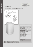
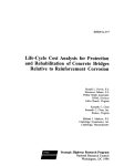
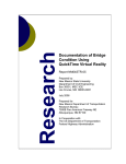
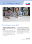
USER’S MANUAL (Read the user’s manual carefully, before operating the unit)
1.
APPLICATION
Techmartsupp voltage switch (TVS+) is designed for the protection of single phase air conditioners with rated voltage of 220V and
frequency of 50 Hz. The main purpose of TVS+ is to protect the A/C unit from unallowable voltage drops, fluctuations in the main
power circuit, overload, and automatic turning ON the unit after the voltage recover and return to normal values with the user defined
time delay. Total maximum power that could be connected to TVS+ is 4.0kw (20A AC-1).
TVS+ contains built-in high frequency filter which additionally protects air conditioners from impulse interruptions.
On the front panel there is a digital display indicating the acting value of input voltage during operation and when pressing the
setting keys it shows the precise parameter values adjusted by user. Additional LED indicator “LOAD’’ shows the ON/OFF state
of the output relay (ON/OFF state for the connected equipment).
2.
GENERAL DESCRIPTION AND OPERATION
TVS+ has three main functional states:
NORMAL OPERATION MODE: In this mode, if the controlled voltage within range and the auto reclosing time after the voltage
interruption has expired, TVS+ will keep on working in this mode. Equipment in this mode is connected to the power supply and turned
ON, LED light green and instantaneous voltage value is indicated on the digital display.
VOLTAGE FAULT ALARM MODE: If the voltage exceeds the preset threshold, the TVS+ switches load off and the LED light RED. If
the fault is voltage related, the digital display will blink continuously showing the value of the unacceptable voltage. When the voltage is
restored within the pre-set range, voltage is restored after the expiration of the delay time and the LED turns GREEN
AUTO RECLOSING TIME MODE: In this mode, TVS+ resumes back to its normal operation mode when the voltage parameters return
back to normal values on the digital display of the switch, the remaining time of auto- reclosing is display in seconds.
OVERLOAD TRIP MODE: This protective mode is activated when load current exceeds 20A. The circuit breaker (switch) trips off to
disconnect the input of the relay. Reset after a technical person has been called to investigate the actual cause of the trip.
: low voltage directive 2014/35/EU
Registration No: AT011504008S
Patent Registration No: NG/PT/NC/2015/932
: Electromagnetic compatibility Directive: 2014/30/EU
Registration No: AT011504008E
3.
TECHNICAL SPECIFICATIONS
Rated voltage, V
Rated voltage frequency, Hz
Adjustable settings ranges:
- Minimal voltage tripping threshold (Umin), V
- Maximal voltage tripping threshold (Umax), V
- Auto-reclosing time delay, sec
Fixed tripping time delay when input voltage exceeds the minimal tripping threshold (Umin), sec
220
47 – 65
Fixed tripping time delay when input voltage exceeds the maximal tripping threshold (Umax ), sec
1
Fixed tripping time delay in case of voltage decrease more than 60V than the adjusted
minimal voltage tripping threshold (Umin), sec
Fixed tripping time delay in case of voltage increase more than 30V than the adjusted
maximal voltage tripping threshold (Umax), sec
Maximal commutation current (active power load), A (not less than) AC-1 type
Accuracy for tripping basing the voltage level measurement, V
Minimal operation voltage level at which TVS will keep working, V
Maximal operation voltage level at which TVS will keep working, V
Voltage hysteresis, V (not more than)
Operational temperature range, °С
Storage temperature, °С
Total power consumption, mA
Commutation lifetime of the output contacts:
- under 20A power load, times (not less than)
- under 5A power load, times (not less than)
Outer dimensions, mm
Net weight, kg
Wall mounting in vertical position in order to read the digits of the front panel indicator
FIG. 1 - Controls Description and Dimensions Diagram
1234567-
Switch; To power ON/OFF and Reset;
Main Relay; Consisting of the LEDs, PCB and Buttons;
Screwless cover;
LED indicator; Glow green when there’s output and Red when there’s no output;
LED Display; Indicate voltage, faults & count down Time.
Scroll up button;
Program/ Scroll down button.
TECHMARTSUPP SOLUTIONS LTD
140 – 220
230 – 280
005 –900
12
0.2
0.2
28
<3
100
420
5
from -25 to + 45
from -45 to + 70
< 60
100 000
1 000 000
86 * 86 * 42
0.13
4.
WIRING AND TERMINALS
TERMINAL
IN:L
IN:N
G:G
O:N
O:L
DESCRIPTION
INPUT LIVE
INPUT NEUTRAL
GROUND
OUTPUT NEUTRAL
OUTPUT LIVE
Fig 2 – Schematic Diagram of The Connection Terminals of TVS+
5. PROGRAMMING
5.1 MAXIMUM VOLTAGE: Press 7 for 3s, it’ll enter the maximum voltage adjust mode and display "S-H", release the
key and press again (within 3s) to decrease voltage in steps of 5V; press 6 to increase voltage in steps of 5V between 230280 volts . Release both buttons for 3 Sec and the set value will be remembered.
5.2 MINIMUM VOLTAGE: Press 7 for 3s, it will enter program mode, and display "S-H" While still holding 7, press 6
once, it’ll enter the minimum voltage adjust mode and at this point you’ll see "S-L”, Release both buttons and press 7 again
(within 3s) to decrease voltage in steps of 5V; or Press 6 to increase voltage in steps of 5V between 140-230 Volts. . Release
both buttons for 3 Sec and the set value will be remembered.
5.3 DELAY TIME: Press 7 for 3s, it will enter program mode, and display: "S-H" While still holding 7, press 6 twice, it’ll
enter the time adjust mode and at this point you’ll see "S-t” , Release the 2 keys and press 6 again (within 3s) to increase time
in step of 5s (between 0-60s) or step of 30s (between 60-900s), and press 7 to decrease time in step of 5s (between 0-60s) or
step of 30s (between 60-900s). . Release both buttons for 3 Sec and the set value will be remembered.
In a case of overload (i.e current >20A) the switch will trip off automatically and after the problem is solved, manual press
the switch to put it on and reset it.
NOTE: When the input voltage is within the pre-set value and the delay time has expired, the output loads is energized and
the LED light is GREEN, otherwise, the LED light RED and the voltage parameter continue to blink.
6. SAFETY PRECAUTIONS
Ensure the switch is not installed at a place exposed to water
Ensure that the conductor of the cable is not exposed after connection to the switch
Ensure that the cables are properly terminated during installation
The power of the switch load should not exceed the value as indicated in the given manual, as it may lead to relay contact
overheat and unit fire
Never attempt to operate TVS+ with the mechanical damage of the unit
Do not use abrasives or organic compounds for cleaning (spirit, solvents etc)
Do not operate the unit under the condition of high humidity
Installation, adjustment and maintenance of the unit should only be provided by the qualified personnel, having
reviewed this manual.
TECHMARTSUPP SOLUTIONS LTD
6.1 ORDER OF MAINTENANCE
Maintenance consist of visual examination, during which reliability of wires to TVS+ clamp connections and absence of
spalls and crack on the case must be check.
7. WARRANTY AND CLAIMS CONDITION
The manufacturer warrants defect-free performance of device within 12 months after the sale date, provided that the
following conditions have been met:
Ø
Proper installation; this involves proper cable termination in accordance with the IP requirement of the device
Ø
The casing is not tampered with i.e. no traces of, cracks, spalls etc.
Production date _________________________
Sales date ___________________
For More Information, Please contact:
TECHMARTSUPP SOLUTIONS LTD.
3B, Olaide Benson Str.,
Maryland, Ikeja
Lagos, Nigeria.
Tel: +2348067480005; +2348053271176
[email protected]; www.techmartsupp.com
TECHMARTSUPP SOLUTIONS LTD