1
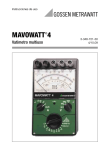
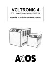
Operating Instructions ® MAVOWATT 4 Multifunction Power Meter 3-348-721-02 4/7.09 1 2 3 4 A V 5 6 Figure 1 2 GMC-I Messtechnik GmbH Operating controls 1 Connection terminals 2 3 4 5 6 Current Voltage Mirror scale Mechnical zero adjuster Selector switch for voltage ranges Selector switch for current ranges Function switch I* (1), I (3) L1 (2), L2 (5), L3 (8) 50 V / 100 V / 250 V / 500 V 0.25 A /1 A /5 A / 25 A Symbols The position of the function switch is marked by symbols. Where: Meter in the "OFF" position –1 –2 Battery test for the voltage path of the meter Battery test for the current path of the meter Measurement of the active power on a three-wire, three-phase systems, balanced load Measurement of the active power on a DC and single-phase AC system U I U I cos ind cos cap L1L2L3 ! Measurement of AC voltage Measurement of AC current Measurement of DC voltage Measurement of DC current Measurement of the power factor, inductive Measurement of the power factor, capacitive Phase sequence indication Danger warning ((Caution: Note documentation) Further symbols Indicates EC conformity This device may not be disposed of with the trash. Further information regarding the WEEE mark can be accessed on the Internet at www.gossenmetrawatt.com by entering the search term ’WEEE’. GMC-I Messtechnik GmbH 3 Contents 1 Safety precautions .....................................................................5 2 Application .................................................................................6 3 Getting started ...........................................................................7 3.1 3.2 3.3 3.4 Description of the operating controls ..........................................................7 Installing the batteries ...............................................................................7 Mechanical zero check ..............................................................................7 Battery test ...............................................................................................8 4 Measurement .............................................................................8 4.1 4.2 4.3 4.4 4.5 4.5.1 4.5.2 4.5.3 Notes on measurements ...........................................................................8 Connection circuitries ..............................................................................10 Measured results ....................................................................................13 Internal consumption of the power meter and its influence on the accuracy 15 Voltage and current measurement ...........................................................16 Voltage measurement .............................................................................16 Current measurement .............................................................................17 Phase sequence indication ......................................................................17 5 Specifications ..........................................................................18 6 Maintenance ............................................................................22 6.1 Battery and Fuse Replacement ................................................................22 7 Repair and Replacement Parts Service Calibration Center and Rental Instrument Service ...................23 8 Product Support .......................................................................24 4 GMC-I Messtechnik GmbH 1 Safety precautions This instrument fulfills the requirements of the applicable European and national EC guidelines. We confirm this with the CE marking. The relevant declaration of conformity can be obtained from GMC-I Messtechnik GmbH. The multi-function power meter MAVOWATT 4 is constructed and tested in compliance with the safety rules of DIN VDE 0410 /IEC 414 and VDE 0411-1/EN 61010-1/IEC 61010-1. When properly used, the safety of both the user and the meter is assured. Their safety is not assured, however, if the meter is misused or carelessly handled. To maintain the technically safe and proper condition and to ensure safe operation, it is absolutely necessary to carefully and completely read these operating instructions before using the meter, and to follow them in all respects. Please note the following safety precautions: • The meter must only be operated by persons who understand the danger of shock hazards and know how to apply safety precautions. Shock hazards exist wherever voltages of more than 50 V can appear. • When making measurements where shock hazards exist, do not work alone. A second person must be present. • The maximum permissible voltage between any of the connectors and ground is 650 V. • Take into account that unexpected voltages can appear on devices under test, capacitors may be charged dangerously, for instance. • Verify that the test leads are in good condition, e.g. no cracked insulation, no open circuits etc. • This meter must not be used for measurements on circuits with corona discharge (high voltage). • Measurements under moist environmental conditions are not permitted. • Absolutely verify that overloading of the nominal voltage and nominal current ranges does not exceed the permissible limits. See chapter 5 „Specifications“ for limits. GMC-I Messtechnik GmbH 5 Repair, replacement of parts and calibration When opening the meter, live parts may be exposed. Therefore, the meter must be disconnected from all voltage sources prior to opening its case for repair, replacement of parts or calibration. If repair or calibration can then not be avoided unless the meter is open and live, this work must only be performed by a qualified person who understands the danger involved. Faults and extraordinary stress When it must be assumed that safe operation is no longer possible, take the meter out of service and secure it against accidental use. It must be assumed that safe operation is no longer possible, • when the meter shows obvious signs of damage, • when the meter no longer functions correctly, • after prolonged storage under adverse conditions. 2 Application The electronic multi-function power meter MAVOWATT 4 permits direct power measurements on DC systems as well as active power measurements on single-phase AC systems and on three-wire, threephase systems of balanced load. In addition, the MAVOWATT 4 power meter can be used to directly measure current and voltage on DC and single-phase AC systems. Under consideration of correction factors, it is also possible to use the meter for reactive power measurements on three-phase systems of balanced load and also for interlinked voltages. The MAVOWATT 4 power meter is particularly suited for industrial measurements, for service and mounting. Also in the laboratory and in the test room, diversified measuring tasks can be solved quickly and without problems. 6 GMC-I Messtechnik GmbH 3 Getting started 3.1 Description of the operating controls There are five connection terminals (1, figure 1), arranged on the front of the power meter, two for current connection with the markings I* (1) and I (3) and three for voltage connection with the markings L1 (2), L2 (5) and L3 (8). They are contact-protected. The operating panel of the power meter consists of: One selector switch for the voltage ranges (4, figure 1), with the four ranges 50 V, 100 V, 250 V and 500 V. One selector switch for the current ranges (5, figure 1), which can be switched in four ranges 0.25 A, 1 A, 5 A and 25 A. One function switch (6, figure 1) featuring 12 positions. 3.2 Installing the batteries Caution: ! Make an all-pole disconnection of the meter from the measuring circuits before you open the battery compartment on the bottom! Undo the slotted screw of the battery compartment cover using an adequate tool or a coin, and remove the cover. Install two 9-V flat cell batteries 6F22, 6LF22 or 6LR61 according to IEC 86-2 in the two compartments. Caution: ! Except for the specified 9-V flat cell batteries, no other voltage souces must be connected to the battery connection contacts. The connection contacts must not be connected with each other! Replace the cover and screw-tighten it. 3.3 Mechanical zero check Check that the meter is switched off. Place the meter in a horizontal position. Check the mechanical zero position of the pointer. If required, correct the zero position with the adjuster " 0 " on the front panel. GMC-I Messtechnik GmbH 7 3.4 Battery test To test the battery for the voltage path and the battery for the current path, set the function switch to the positions " 1" and " 2", one after another. When, at a time, the pointer is within the battery section marked " " on the scale, the battery voltages are within the permissible range. It is assured that the error limits according to the data given in chapter 5 „Specifications“ are maintained. 4 Measurement 4.1 Notes on measurements Prior to connecting the meter, check according to which of the circuitries shown in the following section the MAVOWATT 4 is to be connected. Find out whether direct connection of current path and voltage path is possible on the basis of the system on which the measurements are to be made and with respect to the power to be measured. Caution: ! In systems having a voltage of more than 600 V, measurements must, on principle, only be made via current and voltage transformers! The nominal currents and nominal voltages of the meters correspond to those of commercial current transformers with secondary currents of 1 A and 5 A, and the standardized voltage transformers with secondary voltages of 100 V or 110 V. When using current transformers, consider the secondary load. Particularly with longer connection leads and with a transformer having a secondary current of 5 A, the power loss on the lines is often remarkable. Set up the current path mechanically solid and secure it against accidental opening. Lay out the cross sections of the leads and the connection points in such a way that they will not heat-up unpermissibly. For currents above 5 A, the connections must always be made as screw connections (e.g. with cable lugs), but not as plug connections. 8 GMC-I Messtechnik GmbH Prior to measuring, always set the selector switch for the current ranges and that for the voltage ranges to the highest range. Make sure that the set nominal values are never exceeded by more than 1.2 times. For power measurements on DC and single-phase AC systems, set the function switch to the " " position, for power measurements on three-wire, three-phase systems of balanced load to the " " position. To measure the power factor (cos ), set the function switch to "cos ind" with inductive load, with capacitive load to "cos cap". The connection circuitries for active power and power factor measurements (cos ) are identical and are shown later. Switch the meter off after the measurement to avoid unnecessary load on the batteries (function switch set to position " "). The symbols used in the equations of the connection circuitries have the following meaning: P = Active power in W Q = Reactive power in var I = Load current of a phase in A U = Interlinked generator voltage with three-phase connection in V cos = Power factor a = Readout of the pointer deflection on the corresponding instrument scale in W, V or A a = Readout of the pointer deflection on the cos scale = Scale factor for power measurement cI,cU = Scale constant for current and voltage measurement üI,üU = Scale constant for current and voltage measurement c ,c GMC-I Messtechnik GmbH 9 4.2 Connection circuitries Current and voltage input takes place on the meter via connectors which are suited for both plugging (banana plugs) and as terminals (e.g. cable lugs). The current path is run to the two connectors I* (1) and I (3), the voltage path to connectors L1 (2), L2 (5) and L3 (8). For DC current and for single-phase AC systems, the voltage must be applied to L1 (2) and L2 (5), for three-wire, three-phase systems (without neutral conductor) to L1 (2), L2 (5) and L3 (8). Following is a presentation of the wiring diagrams. The most important diagrams are also affixed to the rear of the meter. Power measurement on DC systems L+ M LM I* I L1 L2 L3 I* I L1 L2 L3 (1) (3) (2) (5) (8) (1) (3) (2) (5) (8) P (W) = I · U = · c 10 GMC-I Messtechnik GmbH Active power and power factor measurement on single-phase AC systems Direct connection: Connection via current transformer: L1 N N (L2) (L2) L1 K L k l I* I L1 L2 L3 I* I L1 L2 L3 (1) (3) (2) (5) (8) (1) (3) (2) (5) (8) P (W) = I · U · cos =·c · üI P (W) = I · U · cos =·c Connection via current and voltage transformer: L1 N (L2) K k P (W) = I · U · cos =·c · üI · üu GMC-I Messtechnik GmbH L U l u V v I* I L1 L2 L3 (1) (3) (2) (5) (8) 11 Active power and power factor measurement on three-wire, three-phase systems, balanced load L1 L2 L3 Direct connection: P (W) = 3 · I · U · cos =·c L1 L1 L2 L3 L2 L3 I* I (1) (3) I* I L1 L2 L3 (1) (3) (2) (5) (8) L1 L2 L3 (2) (8) L1 L2 L3 I* I (2) (8) (1) (3) (5) Connection via current and voltage transformer: Connection via current transformer: L1 L1 L2 L2 L3 L3 K k L l (5) K k L l U u V U V v v u I* I L1 L2 L3 I* I L1 L2 L3 (1) (3) (2) (5) (8) (1) (3) (2) (5) (8) P (W) = 3 · I · U · cos = · c · üI 12 P (W) = 3 · I · U · cos = · c · üI · üu GMC-I Messtechnik GmbH Reactive power measurement on three-wire, three-phase systems of balanced load It is easy to determine the reactive power on three-wire, three-phase systems of balanced load. Set the function switch to the " " position. To obtain the reactive power, multiply the found value (pointer deflection x scale factor) by the factor of 3. With a connection according to the following wiring diagram and a positive indication, the measured reactive power is inductive. With a negative pointer deflection, the measured reactive power is capacitive. To obtain a positive indication, transpose the connection L1 and L2 on the meter (cond. L2 to connector L2 (5) and cond. L3 to connector L1 (2)). L1 Direct connection: L2 L3 Q (var) = 3 · I · U · sin = 3 · · c 4.3 I* I L1 L2 L3 (1) (3) (2) (5) (8) Measured results To determine the measured active power, it is merely required to multiply the pointer deflection with the constant c, and eventually with the transformer ratios. In any case, it applies: P (W) = · c · üI · üU GMC-I Messtechnik GmbH 13 Example 1: Direct connection of the meter for single-phase AC systems Selected nominal current range 5A Selected nominal voltage range 100 V a) Function switch Reading scale according to table Value read off the scale Measured result: in position „ ” 0 ... 500 e.g. 350 P = · c = 350 · 1= 350 W b) Function switch Reading scale according to table Value read off the scale Measured result: in position „U ” 0 ... 100 e.g. 100 U = · cU = 100 · 1 =100 V c) Function switch Reading scale according to table Value read off the scale Measured result: in position „I ” 0 ... 500 e.g. 500 I = · cI = 500 · 0.01 =5A d) Function switch Reading scale according to table Value read off the scale Measured result: in position „cos ind” cos e.g. 0.7 cos = 0.7 Example 2: Meter connection for single-phase AC systems via current transformer Switch positions, reading scale and read value same as in example 1. But the current path is connected via a current transformer having a ratio of üI = 100 A / 5 A = 20. Measured result: P = a · c · üI = 350 · 1· 20 = 7000 W Example 3: Meter connection for single-phase AC systems via current and voltage transformers Switch positions, reading scale, read value and current transformer same as in example 2. But the voltage path is connected via a voltage transformer having a ratio of üU = 1000 V / 100 V = 10. Measured result: P = a · c · üI · üU = 350 · 1· 20 · 10 = 70000 W 14 GMC-I Messtechnik GmbH 4.4 Internal consumption of the power meter and its influence on the accuracy The MAVOWATT 4 power meter needs a certain amount of energy for the presentation of measured values. Due to the internal meter consumption, the measured value always includes an error. In most cases – particularly so when measuring higher power – the influence is so small that it can be neglected. When measuring smaller power (<100 W), it is recommended to consider the internal consumption of the power meter by mathematical correction of the measured result. Depending upon the connection circuit, either the internal consumption of the current path or that of the voltage path enters into the measurement. The voltage path is connected ahead of the current path It follows: a) the power output by the energy source meter reading internal consumption of the voltage path b) the power drawn by the consumer meter reading internal consumption of the current path L1 The voltage path is connected behind the current path It follows: a) the power output by the energy source meter reading internal consumption of the voltage path b) the power drawn by the consumer meter reading internal consumption of the voltage path L1 N (L2) I* I L1 L2 L3 (1) (3) (2) (5) (8) I* I L1 L2 L3 (1) (3) (2) (5) (8) N (L2) See "Inputs" for the internal consumption of the power meter in chapter 5 „Specifications“. GMC-I Messtechnik GmbH 15 4.5 Voltage and current measurement Even if the meter is connected for a power measurement, you can use the power meter to measure voltages and currents on both DC systems and single-phase AC systems and/or three-wire, three-phase systems of balanced load. For DC and single-phase AC systems, the voltage must be applied to L1 (2) and L2 (5). Terminal L3 (8) must not be connected. With three-wire, three-phase systems of balanced load (without neutral conductor), the voltages must be connected to terminals L1 (2), L2 (5) and L3 (8). With current measurements, the measuring current flows through connectors I* (1) and I (3). 4.5.1 Voltage measurement On DC and single-phase AC systems and/or U position and the selector switch for the voltage ranges to the range corresponding to the measured value. The selector switch for the current ranges may be set to any position. Set the function switch to the U The voltage applied to terminals L1 (2) and L2 (5) can be read directly on the scale corresponding to the selected measuring range On three-wire, three-phase systems of balanced load Set the function switch to the U position and the selector switch for the voltage ranges to the range corresponding to the measured value. The selector switch for the current ranges may be set to any position. Connect the voltage to terminals L1 (2), L2 (5) and L3 (8). Read the measured value off the scale corresponding to the selected measuring range To determine the phase voltage, it is required to divide the read voltage value by 3. To determine the voltage of the outer conductors, it is required to divide the read voltage value by 3. 16 GMC-I Messtechnik GmbH 4.5.2 Current measurement Set the function switch to the I and/or I~ position and the selector switch for the current ranges to the range corresponding to the measured value. The selector switch for the voltage ranges may be set to any position. Connect the current path to terminals I* (1) and I (3). Read the measured value off the scale corresponding to the measuring range and multiply it by the factor of 0.01 (see table in chapter 5 „Specifications“). 4.5.3 Phase sequence indication Set the function switch to the L1L2L3 position. Connect all of the 3 outer conductors in proper sequence to terminals L1 (2), L2 (5) and L3 (8). With correct phase sequence, the pointer deflects up to the marking (83 % of full deflection), with incorrect phase sequence up to the marking (17 % of full deflection). The interlinked voltages must be > 30 V and must not exceed 650 V. The connected voltages may deviate from each other by a maximum of 5 %. GMC-I Messtechnik GmbH 17 5 Specifications Measuring ranges for DC and single-phase AC systems Factor c at scale division Nominal Nominal Nominal power voltage current 0...100 0...250 0...500 W V A 0.2 5 1 5 25 50 12.5 100 25 ----- 0.05 --- 0.1 --- 250 500 62.5 --- 0.25 --- 125 --- 0.5 --0.1 50 50 --- --- 100 100 1 --- --- 250 250 --- 1 --- 500 500 --- --- 1 50 250 --- 1 --- 100 500 --- --- 1 250 1250 --- 5 --- 500 2500 --- 10 --- 50 1250 --- 5 --- 100 2500 --- 10 --- 250 6250 --- 25 --- 500 12500 --- 50 --- Measuring ranges for three-wire, three-phase systems, balanced load Nominal Nominal Nominal Factor c at scale division voltage power current A V W 0...100 0...250 0...500 0.25 18 50 25 100 50 ----- 0.1 --- --- 0.1 250 125 --- 0.5 --- 500 250 --- 1 --- GMC-I Messtechnik GmbH Nominal current A 1 5 25 Nominal voltage Nominal power Factor c at scale division V W 50 100 0...100 1 0...250 --- 0...500 --- 100 200 2 --- --- 250 500 --- --- 1 500 1000 10 --- --- 50 500 --- --- 1 100 1000 10 --- ----- 250 2500 --- 10 500 5000 --- --- 10 50 2500 --- 10 --- 100 5000 --- --- 10 250 12500 --- 50 --- 500 25000 --- 100 --- Measuring ranges for DC and AC voltage Nominal voltage V for DC and AC voltage Factor c at scale division 0...100 0...250 0...500 Nominal current A Factor c at scale division 0...100 0...250 0...500 50 --- --- 0.1 0.25 --- 0.001 100 1.0 --- --- 1 0.01 --- ----- 250 --- 1.0 --- 5 --- --- 0.01 500 --- --- 1.0 25 --- 0.1 --- When measuring the power factor (cos ), read the measured values off the cos scale without taking into consideration factor c. GMC-I Messtechnik GmbH 19 Inputs Voltage path Nominal voltage UN Input resistance Ri 50 V / 100 V / 250 V / 500 V 1 M Current path Nominal current IN Input resistance Ri 0.25 A / 1 A / 5 A / 25 A 8 m Voltage drop U at nominal current 2.1 mV / 8.4 mV / 42 mV/ 210 mV Internal consumption Pi at nom. current 0.0005 VA / 0.0084 VA / 0.21 VA /5.25 VA Electrical isolation between voltage path and current path by optocoupler, test voltage 3.7 kV Overload capacity Permissible continuous overload on all nominal voltage and nominal current ranges 1.2 times the value of the selected nominal voltage and/or the selected nominal current. Exception 25 A range: Measurement 5 min at a maximum, interval 5 min Fuse protection The current measuring ranges are protected by a 6 x 32 mm 25 A 500 V/1.5 kA, 250 V/ 10 kA fuse. Accuracy Under reference conditions Class 1.5 for power measurement Class 2.5 in all other ranges Class 5 for power factor measurement In the 25 A range: 2 times the basic error (except for power factor measurement) Reference conditions Ambient temperature 23 C 2 K Humidity 40 ... 60% rel. humidity Position of use horizontal Frequency 45 Hz ... 65 Hz Wave shape on ~: sinusoidal Voltage for voltage measurement: for power factor measurement: 1) for phase sequence indication 2) 0.8 ... 1.2 · UN 0 ... 1.0 · UN > 50 V > 30 V (dev. from each other max. 5%) 20 GMC-I Messtechnik GmbH Current for current measurement: for power factor measurement: 0 ... 1.2 · IN 0 ... 1.0 · IN 0 ... 1.2 · IN / 25 A : 0.3 ... 1.0 · IN Power factor at power factor measurement: cos = 0 ... 0.866 ... 1 cos = 0 ... 0.95 ... 0.99 Battery voltage 6.6 ... 11 V (for each of the two batteries) Other influence quantities according to EN 60 051, IEC 51 Nominal ranges of use Temperature 0 ... 21 ... 25 ... 50 C Frequency for voltage measurement: 10 ... 16 ... 65 ... 400 Hz 10 ... 16 ... 65 ... 200 Hz (... 400 Hz mit Tol. 10%) 10 ... 16 ... 65 ... 400 Hz for current measurement: Influence quantities within the nominal ranges of use Temperature bei W: 1.5% / 10 K bei V, A: 2.5% / 10 K Other influence quantities according to EN 60 051 Ambient conditions Operating temperatures 0 ... 50 C Storage temperatures 25 ... 65 C Power Supply Batteries 2 each 9 V flat cell batt. IEC 6F22, 6LF22 or 6LR61 each one for voltage and current path Lifespan approx. 200 hours Battery test by battery test section on the scale Electrical safety Protection class II per IEC 61010-1/EN 61010-1/VDE 0411-1 Measuring category III Nominal voltage 300 V Pollution degree 2 Test voltage 3.7 kV per IEC 61010-1/EN 61010-1 GMC-I Messtechnik GmbH 21 Electromagnetic Compatibility EMC Interference Immunity and Emission EN 61326 Mechanical Design Display Moving-coil movement Scale length 96 mm Protection type IP 50 per VDE 0470 Partl 1 Dimensions 110 mm x 181 mm x 62 mm Weight approx. 0.8 kg 1) 2) The measurement is independent of the position of the selector switch for the voltage ranges. Symmetry error of the delta voltage with power factor measurement on three-phase systems is 0.5% at a maximum. The measurement is of informative character only. That is why no class accuracy is given. The indication is independent of the position of the selector switch for the voltage ranges. 6 Maintenance 6.1 Battery and Fuse Replacement Caution: ! Disconnect the meter from the measuring circuits before you open the battery compartment. Take care that the cover is replaced before you operate the meter again. Battery Replacement If, when testing the battery, the pointer no longer reaches the battery test section " ", the corresponding battery must be replaced. Replace the exhausted battery with a new, 9-V flat cell battery 6F22, 6LF22 or 6LR61, as described in chapter 3.2 „Installing the batteries“. Fuse Replacement If a fuse blows, eliminate the cause of the overload before placing the instrument back into operation! Open the instrument as described under battery replacement. Remove the blown fuse with the help of an object, such as a test probe, and replace it with a new F25A 500V/1.5kA fuse. 22 GMC-I Messtechnik GmbH Caution ! Be absolutely certain that only the specified fuses are used! The use of a fuse with different triggering characteristics, a different nominal current or a different breaking capacity places the operator, damping diodes, resistors and other components in danger. The use of repaired fuses or short-circuiting of the fuse holder is prohibited. Device Return and Environmentally Compatible Disposal The MAVOWATT 4 is a category 9 product (monitoring and control instrument) in accordance with ElektroG (German Electrical and Electronic Device Law). This device is not subject to the RoHS directive. We identify our electrical and electronic devices (as of August 2005) in accordance with WEEE 2002/96/EG and ElektroG with the symbol shown to the right per DIN EN 50419. These devices may not be disposed of with the trash. Please contact the GMC-I Service GmbH regarding the return of old devices (adress see below). 7 Repair and Replacement Parts Service Calibration Center * and Rental Instrument Service When you need service, please contact: GMC-I Service GmbH Service Center Thomas-Mann-Straße 20 90471 Nürnberg • Germany Phone +49 911 817718-0 Fax +49 911 817718-253 E-Mail [email protected] This address if for Germany only. Abroad, our representatives or establishments are at your disposal. * Calibration Laboratory for Electrical Quantities DKD–K–19701 accredited per DIN EN ISO/IEC 17025:2005 GMC-I Messtechnik GmbH 23 Accredited measured quantities: direct voltage, direct current values, DC resistance, alternating voltage, alternating current values, AC active power, AC apparent power, DC power, capacitance, frequency and temperature 8 Product Support When you need support, please contact: GMC-I Messtechnik GmbH Product Support Hotline Phone +49 911 8602-0 Fax +49 911 8602-709 E-Mail [email protected] Edited in Germany • Subject to change without notice • A PDF version is available on the internet GMC-I Messtechnik GmbH Südwestpark 15 90449 Nürnberg • Germany Phone +49 911 8602-111 Fax +49 911 8602-777 E-Mail [email protected] www.gossenmetrawatt.com