1
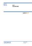
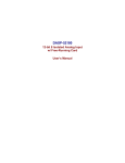
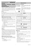
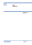
! MICRO-EH (RTD Expansion Unit) Safety Precautions DANGER - Do not touch terminals during power ON. There is a danger of electric shock and/or injury. - Be sure to install external safety devices outside of the PLC like emergency stop circuit or interlock circuit. Thank you for purchasing a Hitachi Programmable Logic Controller. To operate it safely, please read these safety precautions and all the user manuals carefully. Please be sure to use the latest versions of the user manuals and keep them at hand of end users for future reference. ! CAUTION - Be sure that the rated voltage matches the power supply voltage of the unit. Otherwise, there is a danger of breakdown and/or injury and/or fire. - Only qualified personnel shall carry out wiring work. Otherwise, there is a danger of breakdown and/or injury and/or fire. 1. It is not allowed to reprint any part of this manual without permission. 2. The content of this manual may be changed without notice. 3. While efforts have been made on this manual to be accurate, please contact us if any mistakes or unclear part is found. COMPULSION - Be sure to ground the unit. Otherwise, there is a danger of electric shock and/or malfunction. Warranty period and coverage PROHIBITION The warranty period is either 18 months after manufacturing date (MFG No) or 12 months after installation. Examination and repair within the warranty period is covered. However within the warranty period, the warranty will be void if the fault is due to; (1) Incorrect use as directed in this manual and the application manual. (2) Malfunction or failure of external other devices than this unit. (3) Attempted repair by unauthorized personnel. (4) Natural disasters. The warranty is for the PLC only, any damage caused to third party equipment by malfunction of the PLC is not covered by the warranty. - Do not modify or take apart the unit. There is a danger of breakdown and/or injury and/or fire. Mounting -This equipment must be placed within a suitable enclosure such a cabinet (key or tool entry) . - Mount the PLC on a metal plate and install in a cabinet as follows. - Be sure to ground the cabinet and the metal plate, otherwise there is a risk of malfunction. - Install the PLC as described in user manual. - Take appropriate measures when installing systems in locations : • Subject to static electricity or other forms of noise. • Subject to strong electromagnetic field. • Close to power supplies. Repair Any examination or repair after the warranty period is not covered. And within the warranty period any repair and examination which results in information showing the fault was caused by any of the items mentioned above, the repair and examination cost are not covered. If you have any questions regarding the warranty or repair cost, please contact your supplier or the local Hitachi Distributor. (Depending on failure part, repair might be impossible.) - Be sure to tighten mounting screws, terminal screws and connector screws. - Check that devices with lock mechanism, such as an expansion cable and terminal blocks are locked properly. Metal plate Basic unit General cautions AC Definitions and Symbols Grounding ! ! DANGER CAUTION Indicates a potentially hazardous situation which, if not avoided, can result in serious injury or death. Net filter (Recomme nded) Indicates a potentially hazardous situation which, if not avoided, can result in minor to moderate injury, or serious damage of product. AC Power AC enclosure Earth leakage breaker : Indicates prohibition ! Expansion unit Grounding Insulation : Indicates Compulsion -1- NJI-453(X) Figure 1 Power wiring example General Wiring Procedures Other cautions - Use proper cable ferrules for terminals. Using improper cable ferrules or connecting bare wires to terminals directly might result in fire. - Do not turn on power, if the unit appears damaged. - Keep PLC modules in their boxes during storage and transport. - Check carefully your PLC program before using. - Turn off power to the PLC before connecting field wiring. Otherwise, there is a risk of fire. - Do not attempt to disassemble, repair or modify any part of the PLC. - Do not pull on cables or bend cables beyond their natural limit. Otherwise, there is a risk of breaking of wire. Environmental Conditions Avoid the following locations to install the PLC. - Excessive dust, salty air, or conductive materials (iron powder, etc.) - Direct sunlight. - Temperature less than 0°C or more than 55°C. - Humidity less than 5% or more than 95%. - Dew condensation. - Direct vibration or impact to the unit. - Corrosive, explosive or combustible gases. - Water, chemicals or oil splashing on the PLC. - Close to noise emission devices. Power Wiring Procedures - Appropriate emergency circuitry, interlock circuitry and similar safety measures should be added to the system. - Appropriate safety measures should be included in the system unexpected breaking of wire or malsignal caused from instantaneous power failure. - Applied voltage must be in the range specified in the manual. Otherwise, there is a danger of breakdown and/or injury and/or fire. - Install an external earth leakage breakers to avoid short circuit accident. - In case of the followings, turn off power. Otherwise, there is a danger of breakdown and/or injury and/or fire. • Mounting or dismounting CPU or I/O modules. • Assembling cabinet or machine including PLC. • Wiring. - Install net filter specified in table-1. The input and output cable of the net filter should be separated as much as possible. Be sure to ground the net filter. - A shielded and insulated transformer is recommended. - The basic and expansion unit should be wired to a common power source and powered up together as shown in fig.1. Table1 Net filter Item Rated voltage Rated current Withstand voltage (V) (between Terminal and case) Insulation resistance (MΩ) (500VDC, 1 min., between terminal and case) Attenuation frequency range (MHz) Differential mode, 40dB Common mode, 40dB Reference Manual Read the following application manual carefully to use the PLC safely and properly. Be sure to keep the latest version. Manual name Manual No. MICRO-EH APPLICATION MANUAL NJI-350*(X) The postfix of the publication number is subject to change for revision. Spec. 250 V 5A 1500 V min. 100 MΩ 0.5 to 30 0.15 to 30 Reference : EMC filter ZAC2205-00U (TDK) I/O Wiring Procedures - Be sure that the input/output voltage matches the specified voltage. Otherwise, there is a danger of breakdown and/or fire. - Route the AC power line and I/O lines should be separated as much as possible. Do not route both cables in a same duct. - Route the I/O lines and data lines as close as possible to the grounded surfaces such as cabinet elements, metal bars and cabinets panels. -2- NJI-453(X) Specifications General Specifications Item Type Power voltage Power voltage fluctuation range Allowable momentary power failure Operating ambient temperature Operating ambient humidity Vibration resistance Noise resistance Insulation resistance Dielectric withstand voltage Grounding Usage environment Structure Cooling Protection against electrical shock hazard I/O assignment Specification EH-A6ERTD EH-A4ERTD EH-D6ERTD EH-D4ERTD 100/110/120/200/220/240V(50/60Hz) 24V DC 85 to 264V AC 19.2 to 30V DC 85 to 100V :10ms 10ms 100 to 264V:20ms 0 to 55 °C (Storage ambient temperature –10 to 75 °C) 5 to 95 % RH (no condensation) (Storage ambient humidity 5 to 95 % RH (no condensation)) Complies with JIS C 0911 - Noise voltage 1500 Vp-p Noise pulse width 100 ns, 1 micro sec (Noise created by the noise simulator is applied across the power supply module's input terminals. This is determined by this company's measuring methods.) - Based on NEMA ICS 3-304 (with the exception of input module) - Static noise: 3000 V at metal exposed area 20 MΩ or more between the AC terminal and case ground (PE) terminal (based on 500 V DC mega) 1500V AC 500V DC Class D (100Ω) independent grounding No corrosive gases, no excessive dirt Attaches to an open wall Natural air cooling Class 1 equipment Open equipment FUN0 ( X5W / Y3W ) RTD input Specifications No. of input channel RTD type supported Input resolution Input Ranges 4 Pt100 ( 2 or 3 wire ) 0.1 °C / 0.1 °F -100.0 °C to +600.0 °C -148.0 °F to +1112.0 °F Accuracy +/-0.5% of full scale over temp. range Response time 141 / 563 ms Error detection Data H7FFF and LED blinking at below –110°C (-166°F) or beyond +610°C (+1130°F). (including wire breaking or cable disconnection) Cable length (shielded) 100 m (Max.) * * Note : The max. cable length is 100m, however it depends on noise environment or other conditions. Analog output Specifications No. of analog output Output Ranges Resolution Accuracy Response time Current Outputs: Max. Voltage at 20 mA User Load Range Output Load Capacitance Output Load Inductance Voltage Outputs: Output Loading Output Load Inductance * Value in brackets is in case of mode 4000. 2 0-10 V (10.23 V Max.)* 0-20 mA (20.48 mA Max.)* / 4-20 mA (20.38 mA Max.)* 12 Bits +/-1% of full scale over temp. range 8.8 ms 10 V 10 to 500 Ω 2000 pF Max. 1 Henry Max. 10 kΩ Minimum at 10 V 1 micro F Max. -3- NJI-453(X) Terminal configuration EH-A6ERTD (AC power and Analog output type) RTD input and Voltage output Ch2 Ch1 Ch4 Ch3 Input temperature -100 to +600 °C Pt100 IN1B IN1A IN2A IN1b AC NC IN3B IN3A IO6 AC Power supply 100 to 240VAC IN2b IN2B OC6 IN4A IN3b OC7 VO6 - IN4b IN4B VO7 NC IO7 NC + + - Output voltage 0 to +10V Ch6 Ch7 EH-D6ERTD (DC power and Analog output type) RTD input and Current output Ch2 Ch1 Ch4 Ch3 Input temperature -100 to +600 °C Pt100 IN1B IN1A IN1b 0V 24V Power supply 24VDC IN2A IN2b IN2B NC IN3B IN3A IO6 OC6 IN4A IN3b IN4B OC7 VO6 IN4b VO7 IO7 NC NC Output current Ch6 0 to 20mA 4 to 20mA Ch7 EH-A4ERTD (AC power, no analog output version) EH-D4ERTD (DC power, no analog output version) Ch2 Ch1 Input temperature -100 to +600 °C Pt100 IN1B IN1A 0V Power supply 24VDC 24V AC -4- IN2A IN1b AC Power supply 100 to 240VAC Ch4 Ch3 IN2b IN2B NC IN3B IN3A NC NC IN4A IN3b NC NC IN4b IN4B NC NC NC NC NJI-453(X) Wiring and circuit diagram RTD input signal ( Pt100 ) 3 wire Pt100 ( 3 wire ) Be sure to use shielded cable. 1mA 8.2kΩ IN*B 8.2kΩ IN*b 3.3MΩ Signal lines should not be routed close to AC power lines. Internal circuit IN*A Grounding 2 wire* Pt100 ( 2 wire ) Signal lines should not be routed close to AC power lines. 1mA IN*A 8.2kΩ IN*B 8.2kΩ 3.3MΩ IN*b Short circuit between IN*B and IN*b in case of 2-wire system. Grounding * 3-wire system is recommended for this product. Since cable resistance is not cancelled in 2-wire system, it is not suitable for high accuracy measurement especially for long cable used. Analog output signal Voltage output Internal circuit Be sure to use shielded twist pair cable. VO* 10kΩ or more OC* GND Grounding Current output In some cases, capacitor (2000pF or less) is effective. IO* OC* GND 10Ω to 500Ω In some cases, capacitor (0.47µF or less) is effective. -5- NJI-453(X) Data conversion RTD input Data conversion °C/°F Input data °C Dec. Hex. LED (ch.1-4) * 610 °C or more or wire breaking 32767 H7FFF Blinking 600 °C 6000 H1770 Off 0 H0000 Off -100 °C -1000 HFC18 Off -110 °C or less or cable short circuit 32767 H7FFF Blinking 1130 °F or more or wire breaking 32767 H7FFF Blinking 1112 °F 11120 H2B70 Off 0 H0000 Off -1480 HFA38 Off 0 °C °F 0 °F -148 °F -166 °F or less or cable short circuit 32767 H7FFF Blinking * LED blinks depending on input value. Please check wiring by the LED indication. * LED at open channel blinks as it is regarded as wire breaking. This LED blinking can be avoided by short circuit between IN*A and In*b with 100 to 300 Ω resistor. Input data in this case will be undefined value. Analog output 0 to 10V V 10 Mode 4000 Mode 4096 Mode 4096 10V 0FA0H (4000) 0FFFH (4095) 5V 07D0H (2000) 07FFH (2047) 0V 0000H (0) 0000H (0) Resolution 0.0025V approx. 0.00244V Mode 4000 Mode 4096 20mA 0FA0H (4000) 0FFFH (4095) 10mA 07D0H (2000) 07FFH (2047) 0mA 0000H (0) 0000H (0) Resolution 0.005mA Voltage Mode 4000 5 0 07D0H 07FFH 0FA0H 0FFFH (2000) (2047) (4000) (4095) 0 to 20 mA mA 20 Mode 4000 Current 10 0 Mode 4096 approx. 0.00488mA 07D0H 07FFH 0FA0H 0FFFH (2000) (2047) (4000) (4095) -6- NJI-453(X) 4 to 20 mA Mode 4000 mA 20 Mode 4096 Mode 4096 20mA 0FA0H (4000) 0FFFH (4095) 12mA 07D0H (2000) 07FFH (2047) 4mA 0000H (0) 0000H (0) Resolution 0.004mA approx. 0.00391mA Current 12 4 0 Mode 4000 07D0H 07FFH 0FA0H 0FFFH (2000) (2047) (4000) (4095) Range configuration RTD input ( Common for all channels ) Sw1 °C/°F switching °C (Celsius) °F (Fahrenheit) Remarks Factory default Sw2 Response time 563 ms 141 ms Remarks Factory default OFF ON OFF ON SW 1 → 1 Analog output (Common for all channels) Sw4 OFF OFF ON ON Sw5 OFF ON OFF ON Range 0 - 10V Dip switch ( Factory default ) Remarks Factory default SW 2 → 2 O OFF N OFF SW 3 → 3 ON SW 4 → 4 SW 5 → 5 OFF SW 6 → 6 ON SW 7 → 7 OFF SW 8 → 8 OFF OFF 0 - 20mA 4 - 20mA OFF Conversion mode Sw6 Mode OFF 4,096 (H0FFF) ON 4,000 (H0FA0) Sw3 : Be sure to set on. Sw7 : Be sure to set off. Sw8 : Be sure to set off. Remarks ON Note : Power up again after adjusting. Factory default I/O assignment, Data allocation I/O assignment : FUN0 WXu00 WXu01 WXu02 WXu03 WXu04 WYu05 WYu06 WYu07 System area RTD input data Ch.1 RTD input data Ch.2 RTD input data Ch.3 RTD input data Ch.4 System area Analog output data Ch.6 Analog output data Ch.7 u : Unit number (1 to 4) Example : Unit 1, Ch.2 → WX102, Signed 16 bits data Do not write any value. Be sure to write 12 bits data (0 to HFFF). Unit 4, Ch.7 → WY407 -7- NJI-453(X) Caution - Basic unit corresponding to an analog expansion unit Be sure to use with basic unit of software version 1.20 or newer. Analog expansion unit is not supported by basic unit of software version 1.12 or older. Software version of basic unit is given in WRF051 of special internal output area. - Data out of the range Value for data out of the range is H7FFF. - Signal level in case written output data is out of range If output data is over the range, the signal stays at the Max. value. If under the range, it stays at the minimum value. Output value is signed 16 bits data. 8000H to 7FFFH (-32768 to 32767) Example : Range 0-10V, 2000H written Æ 10V (10.24V) output Example : Range 4-20mA, FFFFH written Æ 4mA output ・LED indication LED Lighting POW - Power supplied to exp. unit - Power supplied to the next connected unit. OK Unit OK ch.1-4 - off No power supplied. Blinking - - No power supplied to basic unit. - Expansion cable disconnected - RTD connected properly. Unit has fault. Power up again, or replace it. - Wire breaking or short circuit * - Data out of the range * Since wire breaking only at IN*B or short circuit only between IN*B and IN*b can not be detected by the module, LED indication is off in those cases. - UL requirements This PLC is certified UL508 CSA C22.2 No142-M1987, UL 1604 (CSA C22.2 No.142-M1987). Hazardous locations is suitable for use in Class 1, Div.2 Groups A, B, C & D. Power down before installation, exchanging unit and wiring. -8- NJI-453(X)