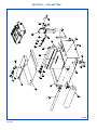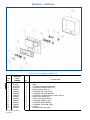
1
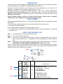
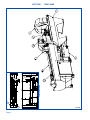
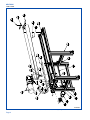
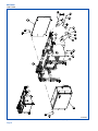
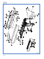
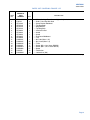
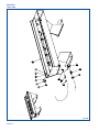
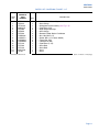
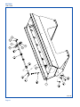
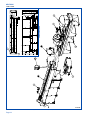
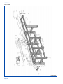
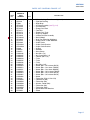
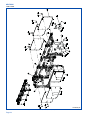
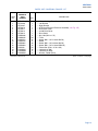
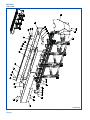
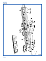
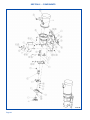
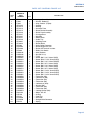
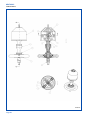
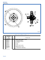
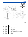
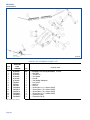
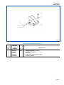
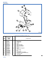
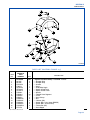
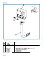
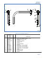
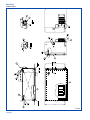
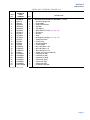
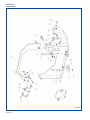
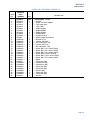
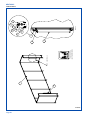
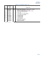
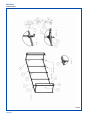
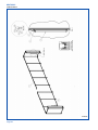
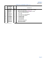
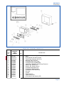
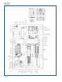
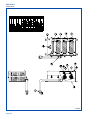
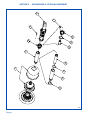
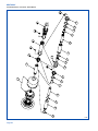
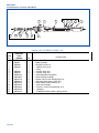
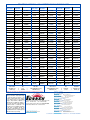
REPAIR PARTS CATALOG
FOR
SUNNEN® 2 & 4M TUBE HONES
MODEL:
HTA-2000 & HTA-4000
THIS CATALOG COVERS THE ABOVE
MODEL WITH THE FOLLOWING
SERIAL NO. 1015 & UP.
“SUNNEN® AND THE SUNNEN LOGO ARE REGISTERED TRADEMARKS OF SUNNEN PRODUCTS COMPANY.”
SUNNEN® PRODUCTS COMPANY
7910 MANCHESTER ROAD • ST. LOUIS, MO 63143, U.S.A. • PHONE: 314-781-2100
X-HTA-2402G
Like any machinery, this equipment may
be dangerous if used improperly. Be
sure to read and follow instructions for
operation of equipment.
ii
INTRODUCTION
Illustrations show all major components in exploded detail. Item numbers on each illustration are keyed to
the corresponding parts list, providing a descriptive identification of each part.
The parts lists include assemblies as well as detail parts. An item listed without a part number can be
obtained as a component of the complete assembly of which it is a part.
Standard hardware items are listed with complete descriptions, such as Item 17 below. These may be
purchased at your local hardware store, but it is important to replace an item with one having the same
dimensions as the original. In some places brand names and part numbers are shown. These may change
depending upon availability.
Sunnen Products Company reserves the right to make changes, without notice, to materials,
specifications, colors, designs and accessories included with units.
HOW TO ORDER
When ordering replacement parts be sure to include the following information to ensure prompt shipment of
correct parts:
1. The part number and description of each part desired, obtained from this parts catalog.
2. The quantity of each part desired.
3. The voltage, frequency and phase, when ordering electrical parts.
4. The model and serial number of the machine, obtained from the name plate, where there is any question
concerning a part.
HOW TO USE THIS PARTS LIST
Step 1. – Locate desired part on illustration. Note item number.
Step 2. – Locate item number in the parts list.
Step 3. – If the item has a part number listed, order by part number and the description. A part number in
light face type indicates that it is a component of the last preceding part number in bold face
type.
Step 4. – If no number is listed, order the part number of the unit of which the desired part is a component.
ORDER ONLY BY PART NUMBER AND DESCRIPTION – NOT by item number.
NOTE: In this manual, parts may be followed by “(For CE Machines)” or “(For Non-CE Machines)” to denote
domestic machines from exported machines. The CE version is constructed to meet the requirements of the
European market, and is available to any customer.
1
Step 1.
4
2
3
15
17
14
Step 2.
Step 3.
Step 4.
ITEM
NO.
ORDER BY
PART
NUMBER
QTY.
1
2
3
4
MVH-4499A
PHSM-405
PHW-354
MVH-4422
1
3
3
1
....Spindle Cap includes
......Screw (M6 x 1 x 16 SHCS)
......Washer (M6)
....Inner Spindle Nose
14
15
16
17
PEM-870A
PEM-871
PEM872
PHSM-600
1
1
1
1
....Cable Carrier includes
......Cable Carrier Bracket
......Cable Carrier Bracket
....Screw (M3 x 0,5 x 5mm FHCS)
iii
DESCRIPTION
GENERAL INFORMATION
The Sunnen® equipment has been designed and engineered for a wide variety of parts within the capacity and limitation of the equipment. With proper care
and maintenance this equipment will give years of service.
READ THE FOLLOWING INSTRUCTIONS CAREFULLY AND THOROUGHLY BEFORE UNPACKING, INSPECTING, OR INSTALLING THIS
EQUIPMENT.
IMPORTANT: Read any supplemental instructions BEFORE installing this equipment. These supplemental instructions give you important information to
assist you with the planning and installation of your Sunnen equipment.
Sunnen Technical Service Department is available to provide telephone assistance for installation, programming, & troubleshooting of your Sunnen
equipment. All support is available during normal business hours, 8:00 AM to 4:30 PM Central Time. Emergency breakdown support is available on a 24
hour / 7 day basis.
Review all literature provided with your Sunnen equipment. This literature provides valuable information for proper installation, operation, and maintenance
of your equipment. Troubleshooting information can also be found within the Instructions. If you cannot find what you need, call for technical support.
Where applicable, programming information for your Sunnen equipment is also included. Most answers can be found in the literature packaged with your
equipment.
Help us help you. When ordering parts, requesting information, or technical assistance about your equipment, please have the following
information available:
• Have ALL MANUALS on hand. The Customer Services Representative or Technician will refer to it.
• Have Model Number and Serial Number printed on your equipment Specification Nameplate.
• Where Applicable: Have Drive model and all nameplate data. Motor type, brand, and all nameplate data.
For Troubleshooting, additional information may be required:
• Power distribution information (type - delta, wye, power factor correction; other major switching devices used, voltage fluctuations)
• Installation Wiring (separation of power & control wire; wire type/class used, distance between drive and motor, grounding).
• Use of any optional devices/equipment between the Drive & motor (output chokes, etc.).
For fast service on your orders call:
Sunnen Automotive Customer Service toll free at: 1-800-772-2878
Sunnen Industrial Customer Service toll free at: 1-800-325-3670
Customers outside the USA, contact your local authorized Sunnen Distributor.
Additional information available at: http://www.sunnen.com or e-mail: [email protected]
NOTE: Sunnen reserves the right to change or revise specifications and product design in connection with any feature of our products contained herein.
Such changes do not entitle the buyer to corresponding changes, improvements, additions, or replacements for equipment, supplies or accessories
previously sold. Information contained herein is considered to be accurate based on available information at the time of printing. Should any discrepancy of
information arise, Sunnen recommends that user verify the discrepancy with Sunnen before proceeding.
ESD PREVENTION REVIEW
Let's review the basics of a sound static control system and its effective implementation. First, in the three step plan:
1.
Always ground yourself when handling sensitive components or assemblies.
2.
Always use a conductive or shielded container during storage or transportation. These materials create a Faraday
cage which will isolate the contents from static charges.
3.
Open ESD safe containers only at a static safe work station.
At the static safe work station, follow these procedures before beginning any work:
A.
Put on your wrist strap or foot grounding devices.
B.
Check all grounding cords to make sure they are properly connected to ground, ensuring the effective dissipation of static charges.
C.
Make sure that your work surface is clean and clear of unnecessary materials, particularly common plastics.
D.
Anti-static bubble wrap has been included for use at the machine when an ESD safe workstation is not available.
You are now properly grounded and ready to begin work. Following these few simple rules and using a little common sense will go a long
way toward helping you and your company in the battle against the hazards of static electricity. When you are working with ESD sensitive devices, make sure you:
GROUND
ISOLATE
NEUTRALIZE
iv
SUNNEN® LIMITED PRODUCT WARRANTY
Sunnen® Products Company and its subsidiaries (SPC) warrant that all new SPC honing machines, gaging equipment, tooling, and related equipment will
be free of defects in material and/or workmanship for a period of one year from the date of original shipment from SPC.
Upon prompt notification of a defect during the one-year period, SPC will repair, replace, or refund the purchase price, with respect to parts that prove to be
defective (as defined above). Any equipment or tooling which is found to be defective from improper use will be returned at the customer's cost or repaired
(if possible) at customer's request. Customer shall be charged current rates for all such repair.
Prior to returning any SPC product, an authorization (RMA#) and shipping instructions must be obtained from the Customer Service Department or items
sent to SPC will be returned to the customer.
Warranty Limitations and Exclusions This Warranty does not apply to the following:
• Normal maintenance items subject to wear and tear: (belts, fuses, filters, etc).
• Damages resulting from but not limited to:
› Shipment to the customer (for items delivered to customer or customer's agent F.O.B., Shipping Point)
› Incorrect installation including improper lifting, dropping and/or placement
› Incorrect electric power (beyond +/- 10% of rated voltage) including intermittent or random voltage spikes or drops
› Incorrect air supply volume and/or pressure and/or contaminated air supply
› Electromagnetic or radio frequency interference from surrounding equipment (EMI, RFI)
› Storm, lightning, flood or fire damage
› Failure to perform regular maintenance as outlined in SPC manuals
› Improper machine setup or operation causing a crash to occur
› Misapplication of the equipment
› Use of non-SPC machines, tooling, abrasive, fixturing, coolant, repair parts, or filtration
› Incorrect software installation and/or misuse
› Non-authorized customer installed electronics and/or software
› Customer modifications to SPC software
THE LIMITED WARRANTY DESCRIBED HEREIN IS EXPRESSLY IN LIEU OF ALL ANY OTHER WARRANTIES. SPC MAKES NO REPRESENTATION OR WARRANTY OF
ANY OTHER KIND, EXPRESS OR IMPLIED, WHETHER AS TO MERCHANTABILITY, FITNESS FOR A PARTICULAR PURPOSE OR ANY OTHER MATTER. SPC IS NOT
RESPONSIBLE FOR THE IMPROPER USE OF ANY OF ITS PRODUCTS. SPC SHALL NOT BE LIABLE FOR DIRECT, INDIRECT, INCIDENTAL, OR CONSEQUENTIAL
DAMAGES INCLUDING BUT NOT LIMITED TO: LOSS OF USE, REVENUE, OR PROFIT. SPC ASSUMES NO LIABILITY FOR PURCHASED ITEMS PRODUCED BY OTHER
MANUFACTURERS WHO EXTEND SEPARATE WARRANTIES. REGARDLESS OF ANY RIGHTS AFFORDED BY LAW TO BUYER, SPC's LIABILITY, IF ANY, FOR ANY AND
ALL CLAIMS FOR LOSS OR DAMAGES WITH RESPECT TO THE PRODUCTS, AND BUYER'S SOLE AND EXCLUSIVE REMEDY THEREFORE, SHALL IN ALL EVENTS BE
LIMITED IN AMOUNT TO THE PURCHASE PRICE OF THAT PORTION OF THE PRODUCTS WITH RESPECT TO WHICH A VALID CLAIM IS MADE.
Shipping Damages
Except in the case of F.O.B., Buyer's destination shipments, SPC will not be liable for any settlement claims for obvious and/or concealed shipping damages.
The customer bears the responsibility to unpack all shipments immediately and inspect for damage. When obvious and/or concealed damage is found, the
customer must immediately notify the carrier's agent to make an inspection and file a claim. The customer should retain the shipping container and packing
material.
SUNNEN® SOFTWARE LICENSE AGREEMENT
This document is a Legal Agreement between you, as user and licensee (Licensee), and Sunnen® Products Company (SPC) with respect to preprogrammed
software (Software) provided by SPC for use on SPC Equipment. By using the Software, you, as Licensee, agree to become bound by the terms of this
Agreement.
In consideration of payment of the license fee (License Fee) which is part of the price evidenced by your receipt (Receipt), SPC grants to you as Licensee
a non-exclusive right, without right to sub-license, to use the particular copy of the SPC Software licensed hereunder only on the particular equipment sold with
the Software. SPC reserves all rights including rights not otherwise expressly granted, and retain title and ownership to the Software including all subsequent copies or updates in any media. The Software and all accompanying written materials are covered by copyrights owned by SPC. If supplied on
removable media (floppy disk), you, as Licensee, may copy the Software only for back up purposes; or you may request that SPC copy the Software for you
for the same purposes. All other copying of the Software or of the accompanying written materials is expressly forbidden and is in violation of the Agreement.
The Software and accompanying written materials (including the user's manual, if any) are provided in an "as is" condition without warranty of any kind
including the implied warranties of merchantability and fitness for a particular purpose, even if SPC has been advised of this purpose. SPC specifically does
not warrant that it will be liable as a result of the operation of the Software for any direct, indirect, consequential or accidental damages arising out of the
use of or inability to use such product even if SPC has been advised of the possibility of such use. It is recognized that some states do not allow the exclusion or limitation of liability for consequential or accidental damages and to the extent this is true, the above limitations may not apply.
Any alteration or reverse engineering of the software is expressly forbidden and is in violation of this agreement.
SPC reserves the right to update the software covered by this agreement at any time without prior notice and any such updates are covered by this
agreement.
v
SAFETY INSTRUCTIONS
READ FIRST
This machine, like any equipment, may be dangerous if used improperly. Please
read all warnings and instructions before attempting to use this machine.
Always disconnect power at main enclosure before servicing machine.1
Always wear eye protection when operating this machine.
NEVER open or remove any machine cover or protective guard with power "ON."
Always disconnect power at main enclosure before servicing this equipment.1
DO NOT attempt any repair or maintenance procedure beyond those described in
this book. Contact your Sunnen® Field Service Engineer or Technical Services
Representative for repairs not covered in these instructions.
Due to the wide variety of machine configurations, all possibilities cannot be
described in these instructions. Instructions for safe use and maintenance of
optional equipment ordered through Sunnen, will be provided through separate
documentation and/or training provided by your Sunnen Field Service Engineer or
Technical Services Representative.
DO NOT attempt to defeat any safety device on this machine or on any of the
optional equipment.
If specially built automation components are added to this system, be sure that
safety is not compromised. If necessary, obtain special enlarged work area safety
system from Sunnen Products Co.
Indicates CE version ONLY.
1
DO NOT touch electrical components until main input power has been turned off and CHARGE
lamps are extinguished. WARNING: The capacitors are still charged and can be quite dangerous.
vi
CONTENTS
PAGE
Introduction ..........................................................................................................
How To Order ......................................................................................................
How To Use This Parts List .................................................................................
General Information .............................................................................................
ESD Prevention Review ......................................................................................
Limited Product Warranty ....................................................................................
Sunnen Software License Agreement ..................................................................
General Safety Instructions ..................................................................................
Contents ...............................................................................................................
iii
iii
iii
iv
iv
v
v
vi
1
TUBE HONE
1-A 2 Meter Tube Hone (HTA2000) ...........................................................................
1-B 2 Meter Carriage Base Assembly (HTA3200) .....................................................
1-C 2 Meter Workpiece Base Assembly (HTA2200) ..................................................
1-D Workpiece Base Assembly Module (HTA2100) ..................................................
1-E 4 Meter Tube Hone (HTA4000) ...........................................................................
1-F 4 Meter Carriage Base Assembly (HTA3400) .....................................................
1-G 4 Meter Workpiece Base Assembly (HTA2400) ..................................................
2
4
10
12
14
16
22
COMPONENTS
2-A Carriage Assembly (HTA3100) ............................................................................
2-B Remote Stone Feed Control Hone (HTA9275) ...................................................
2-C Upper Feed Assembly (HTA9110) ......................................................................
2-D Workpiece Fixture Assembly (HTA9500) ............................................................
2-E V-Wedge Chain Clamp Assembly (HTA9550) ....................................................
2-F V-Wedge Assembly (HTA9570) ..........................................................................
2-G Splash Guard Assembly (HTA8100) ...................................................................
2-H Splash Guard Assembly (HTA8200) ...................................................................
2-I HTA Operator Station (HTA5100/5100CE) .........................................................
2-J Control Panel Support Assembly (HTA5105/5105CE) ........................................
2-K Base Electrical Enclosure Assembly (HTA5010). ................................................
2-L Rail Support (HTA2025) ......................................................................................
2-M 2 Meter Guard Assembly; CE Models ONLY (HTA8400) ...................................
2-N 2 Meter Extrusion Guard Assembly; CE Models ONLY (HTA8405) ...................
2-O 4 Meter Guard Assembly; CE Models ONLY (HTA8500) ...................................
2-P 4 Meter Extrusion Guard Assembly; CE Models ONLY (HTA8505) ...................
24
26
28
29
30
31
32
33
34
35
36
38
40
42
44
46
COOLANT TANK
3-A Coolant System Assembly (HTA7000) ................................................................ 48
ELECTRICAL
4-A Operator Box Assembly (HTA5115) ....................................................................
4-B Operator Box Assembly (HTA5115CE) ...............................................................
4-C Main Electrical Panel (HTA5005) .........................................................................
4-D Braking Resistor Assembly (HTA5050) ................................................................
50
51
52
54
ACCESSORIES & OPTIONAL EQUIPMENT
5-A ANR Hone Head Unit w/HTA-MPS Driveshaft .................................................... 56
5-B ANR Hone Head Unit w/HTA-ANR Driveshaft .................................................... 58
5-C ANR-Style Hone Head Unit ................................................................................. 60
“SUNNEN® AND THE SUNNEN LOGO ARE REGISTERED TRADEMARKS OF SUNNEN PRODUCTS COMPANY.”
© Copyright 2010 by Sunnen® Products Company • Printed in U.S.A.
Page 1
10
9
CE MACHINES ONLY
SECTION I - TUBE HONE
HTA2000
FIGURE 1-A – 2 METER TUBE HONE
Page 2
SECTION I
TUBE HONE
PARTS LIST COVERING FIGURE “1-A”
ITEM
NO.
1
2
3
4
5
6
7
8
9
10
ORDER BY
PART
NUMBER
HTA2000
HTA2025
HTA2200
HTA3200
HTA5100
HTA7000
HTA8050
HTA8100
HTA8200
HTA9275
HTA9500
HTA8400
PEM825
N/S indicates Not Shown
QTY.
Ref
1
1
1
1
1
1
1
1
2
1
1
DESCRIPTION
....2 Meter Tube Hone includes
......Rail Support (see Fig. 2-L)
......2000mm Base Assembly (see Fig. 1-C)
......2 Meter Carriage Base Assembly (see Fig. 1-B)
......HTA Operator Station (see Fig. 2-I)
......Coolant System Assembly (see Fig. 3-A)
......Guard Assembly includes
........Splash Guard Assembly (see Fig. 2-G)
........Splash Guard Assembly (see Fig. 2-H)
......Remote Stone Feed Control Hone (see Fig. 2-B)
......Workpiece Fixture Assembly (see Fig. 2-D)
......2 Meter Guard Assembly; CE Models ONLY (see Fig. 2-M)
......Snap Bushing; CE Models ONLY
(Parts continued on next page)
Page 3
SECTION I
TUBE HONE
HTA3200-1
FIGURE 1-B – 2 METER CARRIAGE BASE ASSEMBLY (1 of 3)
Page 4
SECTION I
TUBE HONE
PARTS LIST COVERING FIGURE “1-B”
ITEM
NO.
1
2
3
4
5
6
N/S
7
8
9
10
11
12
13
14
15
16
17
18
19
20
21
22
23
24
ORDER BY
PART
NUMBER
QTY.
HTA3200-1
F4560
HTA3100
HTA3160
HTA3167
HTA3171
HTA3220
HTA32201
HTA5125
PEM1049
PEM1050
PEM1050
PHM630
PHNM436
PHNM487
PHNM505
PHNM506
PHSM459
PHSM512
PHSM541
PHSM959
PHWM407
PHWM530
PHWM536
PMO1000
PPPM511
Ref
4
1
1
1
1
1
1
1
1.77
1
1
1
2
4
24
4
2
4
8
7
7
8
3
1
8
N/S indicates Not Shown
DESCRIPTION
....2 Meter Carriage Base Assembly (1 of 3) includes
......Rigid Strap
......Carriage Assembly (see Fig. 2-A)
......Pan Assembly
......Right Bracket
......Tool Rest
......2 Meter Actuator Assembly
......Belt (2 Meter)
......Energy Chain / Cable Weldment
......Cable Carrier
......Cable Carrier Bracket Set
......Cable Carrier Bracket Set
......Gearbox
......Nut, Self Clinching (M6 x 1,0)
......Locknut (M6 x 1,0)
......T-Nut
......T-Nut
......Screw (M8 x 1,25 x 20mm SHCS)
......Screw (M6 x 1,0 x 16mm FSHCS)
......Screw (M6 x 1,0 x 16mm BSHCS)
......Screw (M8 x 1,25 x 16mm SHCS)
......Lockwasher (M8)
......Washer, Fender (M6)
......Washer, Fender (M8)
......Servo Motor With Resolver
......Elbow
(Parts continued on next page)
Page 5
SECTION I
TUBE HONE
HTA3200-2
FIGURE 1-B – 2 METER CARRIAGE BASE ASSEMBLY (2 of 3)
Page 6
SECTION I
TUBE HONE
PARTS LIST COVERING FIGURE “1-B”
ITEM
NO.
1
2
3
4
5
6
7
8
9
10
11
12
13
14
ORDER BY
PART
NUMBER
QTY.
HTA3200-2
HTA3166
HTA3167
HTA5010
HTA8011
HTA8012
PHNM406
PHNM505
PHSM965
PHSM980
PHSM986
PHW518
PHWM407
PHWM408
PHWM542
Ref
1
1
1
1
1
4
45
16
12
21
29
16
4
8
N/S indicates Not Shown
DESCRIPTION
....2 Meter Carriage Base Assembly (2 of 3) includes
......Left Bracket
......Right Bracket
......HTA Base Electrical Enclosure Assembly (see Fig. 3-B)
......Back Base Cover
......Inside Base Cover
......Nut, Hex (M12 x 1,75)
......T-Nut
......Screw (M8 x 1,25 x 20mm SHCS)
......Screw (M8 x 1,25 x 16mm BSHCS
......Screw
......Flatwasher
......Lockwasher (M8)
......Lockwasher (M12)
......Washer, Fender (M12)
(Parts continued on next page)
Page 7
SECTION I
TUBE HONE
HTA3200-3
FIGURE 1-B – 2 METER CARRIAGE BASE ASSEMBLY (3 of 3)
Page 8
SECTION I
TUBE HONE
PARTS LIST COVERING FIGURE “1-B”
ITEM
NO.
1
2
3
4
5
6
7
8
9
10
11
12
13
14
15
16
17
18
ORDER BY
PART
NUMBER
QTY.
HTA3200-3
F45732
HTA3163
HTA5128
HTA5129
HTA5133
HTA8002
HTA8003
HTA8004
HTA8005
HTA8006
PHNM401
PHNM467
PHNM505
PHSM431
PHSM959
PHSM986
PHW518
PHWM407
Ref
2
12
2
2
1
1
1
1
1
1
1
42
38
4
24
57
52
24
N/S indicates Not Shown
DESCRIPTION
....2 Meter Carriage Base Assembly (3 of 3) includes
......Knob Palm Grip With Stud
......Cover Bracket Weldment
......Trip Dog Body
......Dog Retainer
......Trip Dog Strip
......Interface Guard
......Guard
......Guard
......End Guard Weldment
......Tray
......Nut, Hex (M8 x 1,25)
......Nut, Insert (M8 x 1,8)
......T-Nut
......Screw (M5 x 0,8 x 10mm BSHCS)
......Screw (M8 x 1,25 x 16mm SHCS)
......Screw
......FlatWasher
......Lockwasher (M8)
(Parts continued on next page)
Page 9
SECTION I
TUBE HONE
HTA2200
FIGURE 1-C – 2000mm BASE ASSEMBLY
Page 10
SECTION I
TUBE HONE
PARTS LIST COVERING FIGURE “1-C”
ITEM
NO.
1
2
3
4
5
6
7
8
9
10
11
12
13
N/S
N/S
ORDER BY
PART
NUMBER
HTA2200
CK1292
HTA2100
MAN1079
PEC386
PEM874
PES798
PHNM402
PHSM573
PHWM516
PHWM528
PPP318
PPP528
PPP318
MVH7402
79726
N/S indicates Not Shown
QTY.
1
1
1
1
2
1
2
4
4
4
8
1
1
1
1
2
DESCRIPTION
....2000mm Base Assembly includes
......Hose Clamp
......Workpiece Base Assembly (see Fig. 1-D)
......Pipe Elbow (3/4)
......Right Angle Cord Grip
......Hose Clamp
......Remote E-Stop Station Pushbutton
......Nut, Hex (M4 x 0,7)
......Screw (M4 x 0,7 x 20mm SHCS)
......Flatwasher (M4)
......Lockwasher (M4)
......Pipe Elbow (1-1/2)
......Hose Barb
......Hose Barb
......Hose
......Hose
(Parts continued on next page)
Page 11
SECTION I
TUBE HONE
HTA2100
FIGURE 1-D – WORKPIECE BASE ASSEMBLY MODULE
Page 12
SECTION I
TUBE HONE
PARTS LIST COVERING FIGURE “1-D”
ITEM
NO.
1
2
3
4
5
6
7
8
9
10
11
12
13
14
15
16
ORDER BY
PART
NUMBER
HTA2100
CK1292
CK1328
F1934
F4349GH2
F43419
F43425
HTA2005
KN567
MAN1079
PPP201
PPP394
PPP556
PPP649
PPP655
PPP785
TCS24222
N/S indicates Not Shown
QTY.
1
2
2
4
6
3
6
1
12
2
1
2
1
2
1
2
4
DESCRIPTION
....Workpiece Base Assembly Module includes
....Hose Clamp
....Pipe Hex Bushing
....Screw (3/4-10 x 2 HHCS)
....Stacking Nut
....Bushing, Split
....Clamping Unit
....2000mm Workspace Base
....Screw (5/16-18 x 3/4 HHCS)
....Pipe Elbow (3/4")
....Pipe Tee (3/4")
....Pipe Nipple (3/4")
....Pipe Coupling (3/4")
....Pipe Nipple (3/4")
....Close Nipple (1-1/2”)
....Hose Barb
....Nut, Hex Jam (3/4-10)
(Parts continued on next page)
Page 13
SECTION I
10
9
CE MACHINES ONLY
TUBE HONE
HTA4000
FIGURE 1-D – 4 METER TUBE HONE
Page 14
SECTION I
TUBE HONE
PARTS LIST COVERING FIGURE “1-E”
ITEM
NO.
1
2
3
4
5
6
7
8
9
10
ORDER BY
PART
NUMBER
HTA4000
HTA2025
HTA2400
HTA3400
HTA5100
HTA7000
HTA8050
HTA8100
HTA8200
HTA9275
HTA9500
HTA8500
PEM825
N/S indicates Not Shown
QTY.
Ref
1
1
1
1
1
1
1
1
2
1
1
DESCRIPTION
....4 Meter Tube Hone includes
......Rail Support (see Fig. 2-L)
......4000mm Base Assembly (see Fig. 1-G)
......4 Meter Carriage Base Assembly (see Fig. 1-F)
......HTA Operator Station (see Fig. 2-I)
......Coolant System Assembly (see Fig. 3-A)
......Guard Assembly includes
........Splash Guard Assembly (see Fig. 2-G)
........Splash Guard Assembly (see Fig. 2-H)
......Remote Stone Feed Control Hone (see Fig. 2-B)
......Workpiece Fixture Assembly (see Fig. 2-D)
......4 Meter Guard Assembly; CE Models ONLY (see Fig. 2-O)
......Snap Bushing; CE Models ONLY
(Parts continued on next page)
Page 15
SECTION I
TUBE HONE
HTA3400op10
FIGURE 1-E – 4 METER CARRIAGE BASE ASSEMBLY (1 of 3)
Page 16
SECTION I
TUBE HONE
PARTS LIST COVERING FIGURE “1-E”
ITEM
NO.
1
2
4
5
6
7
8
9
10
N/S
11
12
13
14
15
16
17
18
19
20
21
22
23
24
25
26
27
28
29
30
31
32
33
34
35
36
37
38
39
40
ORDER BY
PART
NUMBER
QTY.
HTA3400op10
CK1328
F4560
HTA3100
HTA3160
HTA3162
HTA3171
HTA3173
HTA3176
HTA3420
HTA34201
HTA3460
HTA5125
PEM1049
PEM10501
PEM10502
PG968
PHM630
PHM872
PHNM436
PHNM467
PHNM487
PHNM504
PHNM505
PHNM506
PHNM507
PHSM459
PHSM512
PHSM541
PHSM658
PHSM959
PHSM965
PHSM986
PHW518
PHWM407
PHWM501
PHWM530
PHWM532
PHWM567
PMO1000
PPPM511
Ref
1
4
1
1
1
1
2
1
1
1
1
1
1
1
1
3
1
1
2
3
4
4
9
12
5
2
4
12
2
4
7
3
8
11
3
12
7
2
1
8
N/S indicates Not Shown
DESCRIPTION
....4 Meter Carriage Base Assembly (1 of 3) includes
......Pipe Hex Bushing
......Rigid Strap
......Carriage Assembly (see Fig. 2-A)
......Pan Assembly
......Energy Cain Rack
......Tool Rest
......Energy Cain Track
......Drip Tray Support
......4 Meter Actuator Assembly
......Belt (4 Meter)
......Drain Pan Extension Weldment
......Energy Chain / Cable Weldment
......Cable Carrier
......Cable Carrier Bracket
......Cable Carrier Bracket
......O-Ring
......Gearbox
......Hose Clamp
......Nut (M6 x 1,0)
......Nut, Insert (M8 x 1,8)
......Locknut (M6 x 1,0)
......T-Nut
......T-Nut
......T-Nut
......Nut (M8 x 1,25)
......Screw (M8 x 1,25 x 20mm SHCS)
......Screw (M6 x 1,0 x 16mm FSHCS)
......Screw (M6 x 1,0 x 16mm BSHCS)
......Screw (M8 x 1,25 x 18mm FSHCS)
......Screw (M8 x 1,25 x 16mm SHCS)
......Screw (M8 x 1,25 x 20mm SHCS)
......Screw
......Flatwasher (5/16 x11/16 x 5/8)
......Lockwasher (M8)
......Flatwasher (M8)
......Washer, Fender (M6)
......Flatwasher (M8)
......Flatwasher (M10)
......Servo Motor With Resolver
......Elbow
(Parts continued on next page)
Page 17
SECTION I
TUBE HONE
HTA3400op20
FIGURE 1-E – 4 METER CARRIAGE BASE ASSEMBLY
Page 18
SECTION I
TUBE HONE
PARTS LIST COVERING FIGURE “1-E”
ITEM
NO.
ORDER BY
PART
NUMBER
QTY.
1
2
3
4
5
6
7
8
9
10
11
12
13
14
15
16
HTA3400op20
HTA3166
HTA3167
HTA5010
HTA8011
HTA8012
HTA8013
PHNM406
PHNM505
PHSM716
PHSM795
PHSM965
PHSM980
PHW518
PHWM407
PHWM408
PHWM542
Ref
1
1
1
1
1
1
4
69
41
4
16
12
53
16
4
8
N/S indicates Not Shown
DESCRIPTION
....4 Meter Carriage Base Assembly (2 of 3) includes
......Left Bracket
......Right Bracket
......HTA Base Electrical Enclosure Assembly (see Fig. 3-B)
......Back Base Cover
......Inside Base Cover
......Base Cover
......Nut, Hex (M12 x 1,75)
......T-Nut
......Screw (M8 x 1,25 x 16mm SHCS)
......Screw
......Screw (M8 x 1,25 x 20mm SHCS)
......Screw (M8 x 1,25 x 16mm BSHCS)
......Flatwasher (5/16 x 11/16 x 5/8)
......Lockwasher (M8)
......Lockwasher (M12)
......Washer, Fender (M12)
(Parts continued on next page)
Page 19
SECTION I
TUBE HONE
HTA3400op30
FIGURE 1-E – 4 METER CARRIAGE BASE ASSEMBLY (3 of 3)
Page 20
SECTION I
TUBE HONE
PARTS LIST COVERING FIGURE “1-E”
ITEM
NO.
ORDER BY
PART
NUMBER
QTY.
1
2
3
4
5
6
7
8
9
10
11
12
13
14
15
16
17
18
19
20
HTA3400op30
F45732
HTA3163
HTA5128
HTA5129
HTA5133
HTA5134
HTA8002
HTA8003
HTA8004
HTA8005
HTA8006
HTA8023
HTA8024
PHNM467
PHNM505
PHSM431
PHSM986
PHSM959
PHW518
PHWM407
Ref
2
20
2
2
1
1
1
1
1
1
1
1
1
65
62
4
73
46
62
46
N/S indicates Not Shown
DESCRIPTION
....4 Meter Carriage Base Assembly (3 of 3) includes
......Knob Palm Grip With Stud
......Cover Bracket Weldment
......Trip Dog Body
......Dog Retainer
......Trip Dog Strip
......Trip Dog Strip
......Interface Guard
......Guard
......Guard
......End Guard Weldmwnr
......Tray
......Right Back Guard
......Left Back Guard
......Nut, Insert (M8 x 1,8)
......T-Nut
......Screw (M5 x 0,8 x 10mm BSHCS)
......Screw (M8 x 1,25 x 16mm HHCS)
......Screw (M8 x 1,25 x 16mm SHCS)
......Flatwasher (5/16 x 11/16 x 5/8)
......Lockwasher (M8)
(Parts continued on next page)
Page 21
SECTION I
TUBE HONE
HTA2400
FIGURE 1-F – 4000mm BASE ASSEMBLY
Page 22
SECTION I
TUBE HONE
PARTS LIST COVERING FIGURE “1-F”
ITEM
NO.
1
2
3
4
5
6
7
8
9
10
11
12
13
14
15
16
17
18
19
20
21
22
23
24
N/S
N/S
ORDER BY
PART
NUMBER
HTA2400
CK1292
HTA2014
HTA2016
HTA2100
MAN1079
PEC386
PEM874
PES798
PHNM402
PHNM406
PHNM436
PHSM453
PHSM573
PHSM971
PHWM408
PHWM516
PHWM528
PHWM542
PPP130
PPP201
PPP318
PPP528
PPP785
PPP786
MVH7402
79726
N/S indicates Not Shown
QTY.
1
3
1
2
2
1
2
3
2
4
6
4
7
4
4
6
8
4
12
2
1
1
3
3
1
1
4
DESCRIPTION
....4000mm Base Assembly includes
......Hose Clamp
......Oil Splash Cover
......Oil Splash Corner Cover
......Work Piece Base Assembly (see Fig. 1-D)
......Pipe Elbow (3/4)
......Right Angle Cord Grip
......Hose Clamp
......Remote E-Stop Station Pushbutton
......Nut, Hex (M4 x 0,7)
......Nut, Hex (M12 x 1,75)
......Nut (M6 x 1,0)
......Screw (M12 x 1,75 x 45mm SHCS)
......Screw (M4 x 0,7 x 20mm SHCS)
......Screw
......Lockwasher (M412)
......Flatwasher (M4)
......Lockwasher (M4)
......Washer, Fender (M12)
......Pipe Plug
......Pipe Tee (3/4”)
......Pipe Elbow (1-1/2)
......Hose Barb
......Hose Barb
......Pipe Tee
......Hose
......Hose
(Parts continued on next page)
Page 23
SECTION II - COMPONENTS
HTA3100
FIGURE 2-A – CARRIAGE ASSEMBLY
Page 24
SECTION II
COMPONENTS
PARTS LIST COVERING FIGURE “2-A”
ITEM
NO.
1
2
3
4
5
6
7
8
9
10
11
12
13
14
15
16
17
18
19
20
21
22
23
24
25
26
27
28
29
30
31
32
33
34
35
36
37
38
39
40
41
42
43
44
N/S
ORDER BY
PART
NUMBER
HTA3100
F3596
F4383
HTA3104
HTA3113
HTA3114
HTA3115
HTA3120
HTA3127
HTA3181
HTA5121
HTA5126
HTA8001
HTA8033
PEC380
PEM1204
PEM1206
PES808
PHM629A
PHNM436
PHNM504
PHSM405
PHSM449
PHSM510
PHSM520
PHSM534
PHSM535
PHSM574
PHSM716
PHSM959
PHSM965
PHWM501
PHWM509
PHWM516
PHWM518
PHWM521
PHWM530
PHWM532
PHWM534
PHWM571
PMO1001
POR109
PPP311
PPPM502
PPPM590
PSP272
N/S indicates Not Shown
QTY.
1
2
1
1
1
1
1
1
1
2
1
1
1
1
1
1
1
1
1
4
10
4
7
4
8
4
4
2
4
2
10
4
4
10
2
4
2
2
4
10
1
2
2
2
2
1
DESCRIPTION
....Carriage Assembly includes
......Washer Reducing
......Grip, Cord 90° (Purple)
......Coupler
......Bearing
......Armature Plate
......Brake Bracket Assembly
......Brake Plate Assembly
......Carriage Base
......Manifold
......Switch Block
......Cable Tray
......Coupling Cover
......Brake Shield
......Strain Relief Connector
......Brake Magnet Coil, 24v
......Brake Coil Terminal Insulator
......Roller Limit Switch
......Gear Reducer
......Nut (M6 X 1,0)
......T-Nut
......Screw (M6 X 1,0 X 16mm SHCS)
......Screw (M10 X 1,5 X 35mm SHCS)
......Screw (M6 X 1,0 X 12mm BSHCS)
......Screw (M4 X 0,7 X 10mm SHCS)
......Screw (M6 X 1,0 X 20mm SHCS)
......Screw (M6 X 1,0 X 12mm SHCS)
......Screw (M4 X 0,7 X 30mm SHCS)
......Screw (M8 X 1,25 X 16mm SHCS)
......Screw (M8 X 1,25 X 16mm SHCS)
......Screw (M8 X 1,25 X 20mm SHCS)
......Flatwasher (M8)
......Lockwasher (M6)
......Flatwasher (M4)
......Flatwasher (M6)
......Lockwasher (M10)
......Washer (M6)
......Flatwasher (M8)
......Flatwasher (M6)
......Locking Washer (M8)
......Motor, 3hP AC
......O-Ring
......Pipe Plug
......Oil Cover
......Straight Male Connector
......Spring
(Parts continued on next page)
Page 25
SECTION II
COMPONENTS
HTA9275
FIGURE 2-B – REMOTE STONE FEED CONTROL HONE
Page 26
SECTION II
COMPONENTS
PARTS LIST COVERING FIGURE “2-B”
ITEM
NO.
1
2
3
4
5
6
7
8
9
10
11
12
13
14
15
ORDER BY
PART
NUMBER
HTA9275
AN640
ANR230
CK1828
F2040
HTA3108
HTA3130
HTA9110
JNR132
MPS175
MPS185
MPS2230
MPS2235
MSN177
PBR24
PHS522
QTY.
Ref.
1
1
2
1
1
1
1
1
1
1
1
1
8
2
2
DESCRIPTION
....Remote Stone Feed Control Hone includes
......Extension Coupler
......Feed Clutch
......Flatwasher
......Ring Snap
......Yoke
......Feed Shaft Assembly
......Upper Feed Assembly (see Fig. 2-C)
......Flatwasher
......U Joint Assembly
......Universal Ring Assembly
......Input Yoke
......Universal Cover
......Screw (#10-32 X 5/8 SHCS)
......Inner Race (Bushing)
......Screw (5/16-24 X 1 BSHCS)
N/S indicates Not Shown
Page 27
SECTION II
COMPONENTS
HTA9110
FIGURE 2-C – UPPER FEED ASSEMBLY
PARTS LIST COVERING FIGURE “2-C”
ITEM
NO.
1
2
3
4
5
6
7
8
9
ORDER BY
PART
NUMBER
HTA9110
ANR115
ANR125
ANR135
ANR141
ANR144
ANR155
G419SF
HTA9145
MSN177
N/S indicates Not Shown
Page 28
QTY.
Ref.
1
1
1
2
2
1
1
1
4
DESCRIPTION
....Upper Feed Assembly includes
......Carriage Assembly
......Feed Shaft Assembly
......Sun Gear
......Gear
......Gear
......Drive Head Assembly
......Pin
......Hand Wheel Assembly
......Screw (#10-32 x 5/8 SHCS)
SECTION II
COMPONENTS
HTA9500
FIGURE 2-D – WORKPIECE FIXTURE ASSEMBLY
PARTS LIST COVERING FIGURE “2-D”
ITEM
NO.
1
2
3
4
5
6
7
8
9
10
N/S
ORDER BY
PART
NUMBER
HTA9500
HTA9505
HTA9508
HTA9509
HTA9510
HTA9550
HTA9570
PHSM453
PHSM455
PHWM549
STH2912
PHP206
QTY.
Ref.
1
2
1
1
1
1
4
1
4
1
2
DESCRIPTION
....Fixture Assembly includes
......Fixture Support
......Fixture Clamp
......Locking Nut
......Screw Assembly
......V-Wedge Chain Clamp Assembly (see Fig. 2-E)
......V-Wedge Assembly (see Fig. 2-F)
......Screw, Socket Head Cap, M12 X 1.75 X 45mm, Plain
......Screw, Socket Head Cap, M12 X 1.75 X 90mm, Plain
......Flatwasher, M12, Plain, Bossard #Bn342
......Fixture Bolt Spacer
......Hitch Pin
N/S indicates Not Shown
Page 29
SECTION II
COMPONENTS
HTA9550
FIGURE 2-E – V-WEDGE CHAIN CLAMP ASSEMBLY
PARTS LIST COVERING FIGURE “2-E”
ITEM
NO.
1
2
3
4
5
6
7
8
9
10
11
12
13
14
ORDER BY
PART
NUMBER
HTA9550
HTA9561
HTA9562
HTA9565
HTA9568
HTA9655
PHM632
PHP206
PHP448
PHSM448
PHSM515
PHSM716
PHSM985
PHWM501
PHWM567
N/S indicates Not Shown
Page 30
QTY.
Ref.
1
1
1
1
1
1
1
2
4
4
2
2
4
4
DESCRIPTION
....V-Wedge Chain Clamp Assembly includes
......Nut Block
......Tension Pin
......Vise Screw
......Handle
......Vee Wedge Weldment
......Leaf Chain
......Hitch Pin
......Roll Pin
......Screw (M10 x 1,5 x 30mm SHCS)
......Screw (M8 x 1,25 x 25mm SHCS)
......Screw (M8 x 1,25 x 16mm SHCS)
......Screw (M10 x 1.5 x 10MM SHCS)
......Flatwasher (M8)
......Flatwasher (M10)
SECTION II
COMPONENTS
HTA9570
FIGURE 2-F – V-WEDGE ASSEMBLY
PARTS LIST COVERING FIGURE “2-F”
ITEM
NO.
1
2
3
4
ORDER BY
PART
NUMBER
HTA9570
HTA9575
PHP206
PHSM448
PHWM567
QTY.
Ref.
1
1
4
4
DESCRIPTION
....V-Wedge Assembly includes
......Vee Wedge Weldment
......Hitch Pin
......Screw ( M10 x 1,5 x 30mm SHCS)
......Flatwasher (M10)
N/S indicates Not Shown
Page 31
SECTION II
COMPONENTS
HTA8100
FIGURE 2-H – SPLASH GUARD ASSEMBLY - TOOL END
PARTS LIST COVERING FIGURE “2-H”
ITEM
NO.
1
2
3
4
5
6
7
8
9
10
11
12
13
14
15
16
17
ORDER BY
PART
NUMBER
HTA8100
891325
891326
ECA7954
F46972
HTA8103
HTA8105
HTA8115
PHM461
PHM464
PHM832
PHM872
PHNM434
PHNM487
PHSM405
PHSM431
PHWM519
PPP570
N/S indicates Not Shown
Page 32
QTY.
Ref.
2
4
1
1
2
1
1
1
20
1
2
8
2
2
2
8
1
DESCRIPTION
....Splash Guard Assembly - Tool End includes
......Bumper Strip
......Bumper Strip
......Handle
......Hose
......Glide Strip Angle
......Splash Guard Base
......Splash Guard Cover
......Nozzle
......Flexible Hose Segment
......Valve
......Hose Clamp
......Nut
......Locknut (M6)
......Screw (M6 x 16mm SHCS)
......Screw (M5 x 0,8 x 10mm BSHCS)
......Flatwasher (M5)
......Hose Nipple
SECTION II
COMPONENTS
HTA8200
FIGURE 2-G – SPLASH GUARD ASSEMBLY - MACHINE END
PARTS LIST COVERING FIGURE “2-g”
ITEM
NO.
1
2
3
4
5
6
7
8
9
10
11
12
13
14
15
16
17
ORDER BY
PART
NUMBER
HTA8200
891325
891326
ECA7954
F46972
HTA8103
HTA8205
HTA8215
PHM461
PHM464
PHM832
PHM872
PHNM434
PHNM487
PHSM431
PHSM535
PHWM519
PPP570
QTY.
Ref.
2
4
1
1
2
1
1
1
20
1
2
8
2
2
2
8
1
DESCRIPTION
....Splash Guard Assembly - Tool End includes
......Bumper Strip
......Bumper Strip
......Handle
......Hose
......Glide Strip Angle
......Splash Guard Base
......Splash Guard Cover
......Nozzle
......Flexible Hose Segment
......Valve
......Hose Clamp
......Nut
......Locknut (M6)
......Screw (M5 x 0,8 x 10mm BSHCS)
......Screw (M6 x 12mm SHCS)
......Flatwasher (M5)
......Hose Nipple
N/S indicates Not Shown
Page 33
SECTION II
COMPONENTS
HTA5100
FIGURE 2-I – HTA OPERATOR STATION
PARTS LIST COVERING FIGURE “2-I”
ITEM
NO.
1
2
2
3
4
5
ORDER BY
PART
NUMBER
HTA5100 / CE
HTA5105CE
HTA5115
HTA5115CE
PHSM535
PHWM509
PHWM518
N/S indicates Not Shown
Page 34
QTY.
Ref.
1
1
1
4
4
4
DESCRIPTION
....HTA Operator Station includes
......Control Panel Support Assembly (see Fig. 2-J)
......Operator Box Assembly (see Fig. 4-A)
......Operator Box Assembly (CE Models ONLY) (see Fig. 4-B)
......Screw (M6 x 1,0 x 12mm SHCS)
......Lockwasher (M6)
......Flatwasher (M6)
SECTION II
COMPONENTS
HTA51050
FIGURE 2-J – CONTROL PANEL SUPPORT ASSEMBLY
PARTS LIST COVERING FIGURE “2-J”
ITEM
NO.
1
2
3
4
5
6
7
8
9
10
11
12
13
14
15
ORDER BY
PART
NUMBER
HTA5105 / CE
CHW721
EC4772
HTA5110CE
ML4312
ML4313
ML4314
ML4317
PHSM405
PHSM506
PHSM514
PHSM618
PHSM984
PHWM408
PHWM512
POR160
QTY.
Ref.
1
1
1
1
1
1
2
4
1
3
3
3
3
3
3
DESCRIPTION
....Control Panel Support Assembly includes
......Stud Type Adjustable Handle
......Bushing
......Control Panel Support
......Adjusting Collar
......Washer
......Enclosure Coupling
......Retainer
......Screw (M6 x 1,0 x 16mm SHCS)
......Screw (M5 x 0,8 x 8mm SHCS)
......Screw (M8 x 1,25 x 20mm FSHCS)
......Screw (M10 x 1,5 x 10mm SHSS)
......Screw
......Lockwasher (M12)
......Flatwasher (M12)
......O-Ring
N/S indicates Not Shown
Page 35
SECTION II
COMPONENTS
HTA5010
FIGURE 2-K – BASE ELECTRICAL ENCLOSURE ASSEMBLY
Page 36
SECTION II
COMPONENTS
PARTS LIST COVERING FIGURE “2-K”
ITEM
NO.
1
2
3
4
5
6
7
8
9
10
11
12
13
14
15
16
17
18
19
20
21
22
23
24
N/S
ORDER BY
PART
NUMBER
QTY.
HTA5010
CK6172
CK6183
HBS2643
HBS2644
HBS2646
HTA5005
HTA5015
HTA5017
HTA5020
HTA5050
PEC379
PEC383
PEM991
PEM994
PHNM401
PHNM407
PHNM419
PHS511
PHWM407
PHWM509
PHWM521
PHWM531
PHWM532
PHWM534
CBL7202000
Ref.
2
1
2
2
2
1
1
2
1
1
1
1
1
1
8
4
4
4
8
4
4
4
8
4
1
DESCRIPTION
....Base Electrical Enclosure Assembly includes
......Enclosure Hinge Half
......Print Holder
......Hold Down Bracket
......Clip Bolt
......Clip Spring
......Main Electrical Panel (see Fig. 4-C)
......Enclosure
......Bracket
......Door
......Braking Resistor Box (see Fig. 4-D)
......Cable Entry Seal
......4 Pole Plug
......Disconnect Shaft
......Pistol Handle
......Nut, Hex (M8 x 1,25)
......Nut, Hex (M6 x 1,0)
......Nut, Hex (M10 x 1,5)
......Screw (#10-24 x 3/8 BSHCS)
......Lockwasher (M8)
......Lockwasher (M6)
......Lockwasher (M10)
......Flatwasher (M10)
......Flatwasher (M8)
......Flatwasher (M6)
......HTA2000 Cable Set
N/S indicates Not Shown
Page 37
SECTION II
COMPONENTS
HTA2025
FIGURE 2-L – RAIL SUPPORT
Page 38
SECTION II
COMPONENTS
PARTS LIST COVERING FIGURE “2-L”
ITEM
NO.
1
2
3
4
5
6
7
8
9
10
11
12
13
14
15
16
17
18
19
20
21
22
23
24
25
26
27
28
29
30
31
ORDER BY
PART
NUMBER
HTA2025
ECA7954
HTA2017
HTA2018
HTA2019
HTA2021
HTA2022
HTA2026
HTA2028
HTA2029
PES809
PHNM436
PHNM441
PHNM467
PHNM487
PHNM507
PHSM405
PHSM415
PHSM424
PHSM532
PHSM598
PHSM607
PHSM987
PHW354
PHWM407
PHWM509
PHWM511
PHWM532
PHWM536
PHWM539
PHWM541
SV54023
QTY.
Ref.
1
1
1
1
1
2
2
1
1
1
6
2
4
2
3
2
2
4
1
4
2
2
3
4
4
2
4
2
3
4
2
DESCRIPTION
....Rail Support includes
......Handle
......Safety Tool Arch Support
......Tool Safety Arch
......Latch Hook
......Holder Support
......Holder Support
......Holder Support
......Handle Cover
......Oil Splash Cover
......Roller Plunger Limit Switch
......Nut (M6 X 1,0)
......Locknut (M5 X 0,8)
......Nut, Insert (M8 X 1,8)
......Locknut (M6 X 1,0)
......Nut, Hex (M8 X 1,25)
......Screw (M6 X 1,0 X 16mm SHCS)
......Screw (M5 X 0,8 X 35mm SHCS)
......Screw (M6 X 1,0 X 20mm HHCS)
......Screw (M10 X 20mm, SHSCS)
......Screw (M8 X 1,25 X 35mm HHCS)
......Screw (M6 X 1,0 X 30mm SHCS)
......Screw
......Flatwasher (M6)
......Lockwasher (M8)
......Lockwasher (M6)
......Flatwasher (M5)
......Flatwasher (M8)
......Washer (M8)
......Flatwasher (M8)
......Flatwasher (M6)
......Washer
N/S indicates Not Shown
Page 39
4
1
Page 40
DIP SWITCH SETTINGS
(INSIDE RECEIVER ENCAP)
S E E D E TA I L A
5
3
2
2e
2h
2d
D E TA I L A
2c
2g
2f
2b
2a
SECTION II
COMPONENTS
HTA8400
FIGURE 2-M – 4 METER GUARD ASSEMBLY - CE
SECTION II
COMPONENTS
PARTS LIST COVERING FIGURE “2-M”
ITEM
NO.
1
2
2a
2b
2c
2d
2e
2f
2g
2h
3
4
5
ORDER BY
PART
NUMBER
HTA8400
HTA8405
HTA8510
HTA8511
PHNM445
PHSM434
PHSM515
PHWM406
PHWM407
PHWM501
PHWM519
PED31581
PED31582
PED31583
QTY.
Ref.
1
4
1
2
3
2
3
2
2
3
1
1
4
DESCRIPTION
....2 Meter Guard Assembly (CE Models ONLY) includes
......Extrusion Guard Assembly (see Fig. 2-N)
......Light Curtain Mountinig Bracket Assembly includes
........Light Curtain Mounting Bracket
........Nut, T-Slot
........Screw (M5 x 0,8 x 16mm BSHCS)
........Screw (M8 x 25mm SHCS)
........Lockwasher (M5)
........Lockwasher (M8)
........Flatwasher (M8)
........Flatwasher (M5)
......Light Curtain, Transmitteer
......Light Curtain, Receiver
......Light Curtain, Bracket
N/S indicates Not Shown
Page 41
SECTION II
COMPONENTS
HTA8405
FIGURE 2-N – 2 METER EXTRUSION GUARD ASSEMBLY - CE
Page 42
SECTION II
COMPONENTS
PARTS LIST COVERING FIGURE “2-N”
ITEM
NO.
1
1a
1b
1c
2
2a
2b
2c
3
3a
3b
3c
4
5
6
7
8
9
10
11
12
13
14
ORDER BY
PART
NUMBER
HTA8505
HTA85051
------HTA85052
------HTA85053
------HTA85055
HTA85056
HTA85057
-----------------
QTY.
Ref.
36
2
1
2
6
1
3
3
16
2
1
2
5
2
2
10
72
4
8
4
10
10
10
DESCRIPTION
....2 Meter Extrusion Guard Assembly (CE Models ONLY) includes
......Angle Assembly E40S
........Nut (M8)
........Angle 90°
........Screw (M8 x 16mm SHCS)
......Support Bracket Assembly
........Column Support Bracket
........Nut (M8)
........Screw (M8 x 16mm SHCS)
......Angle Assembly M25S
........Nut (M8)
........Angle 45°
........Screw (M8 x 20mm SHCS)
......Panel (48 x 79”)
......Panel (36 x 79”)
......Panel (12 x 79”)
......MK Series 40 Cover Plate
......Fence CIip
......Extrusion (40 x 40 x 286,8mm)
......Extrusion (40 x 40 x 304,8mm w/45° Ends)
......Extrusion (40 x 40 x 896,4mm)
......Extrusion (40 x 40 x I201,2mm)
......Extrusion (40 x 40 x 2133,6mm)
......M12 Leveling Pad Assembly
N/S indicates Not Shown
Page 43
SECTION II
COMPONENTS
HTA8500
FIGURE 2-O – 4 METER GUARD ASSEMBLY - CE
Page 44
SECTION II
COMPONENTS
PARTS LIST COVERING FIGURE “2-O”
ITEM
NO.
1
2
2a
2b
2c
2d
2e
2f
2g
2h
3
4
5
ORDER BY
PART
NUMBER
HTA8500
HTA8505
HTA8510
HTA8511
PHNM445
PHSM434
PHSM515
PHWM406
PHWM407
PHWM501
PHWM519
PED31581
PED31582
PED31583
QTY.
Ref.
1
4
1
2
3
2
3
2
2
3
1
1
4
DESCRIPTION
....4 Meter Guard Assembly (CE Models ONLY) includes
......Extrusion Guard Assembly (see Fig. 2-P)
......Light Curtain Mountinig Bracket Assembly includes
........Light Curtain Mounting Bracket
........Nut, T-Slot
........Screw (M5 x 0,8 x 16mm BSHCS)
........Screw (M8 x 25mm SHCS)
........Lockwasher (M5)
........Lockwasher (M8)
........Flatwasher (M8)
........Flatwasher (M5)
......Light Curtain, Transmitteer
......Light Curtain, Receiver
......Light Curtain, Bracket
N/S indicates Not Shown
Page 45
SECTION II
COMPONENTS
HTA8505
FIGURE 2-P – 4 METER EXTRUSION GUARD ASSEMBLY - CE
Page 46
SECTION II
COMPONENTS
PARTS LIST COVERING FIGURE “2-P”
ITEM
NO.
1
1a
1b
1c
2
2a
2b
2c
3
3a
3b
3c
4
5
6
7
8
9
10
11
12
13
14
ORDER BY
PART
NUMBER
HTA8505
HTA85051
------HTA85052
------HTA85053
------HTA85055
HTA85056
HTA85057
-----------------
QTY.
Ref.
48
2
1
2
9
1
3
3
16
2
1
2
8
2
2
13
72
4
8
4
16
13
13
DESCRIPTION
....4 Meter Extrusion Guard Assembly (CE Models ONLY) includes
......Angle Assembly E40S
........Nut (M8)
........Angle 90°
........Screw (M8 x 16mm SHCS)
......Support Bracket Assembly
........Column Support Bracket
........Nut (M8)
........Screw (M8 x 16mm SHCS)
......Angle Assembly M25S
........Nut (M8)
........Angle 45°
........Screw (M8 x 20mm SHCS)
......Panel (48 x 79”)
......Panel (36 x 79”)
......Panel (12 x 79”)
......MK Series 40 Cover Plate
......Fence CIip
......Extrusion (40 x 40 x 286,8mm)
......Extrusion (40 x 40 x 304,8mm w/45° Ends)
......Extrusion (40 x 40 x 896,4mm)
......Extrusion (40 x 40 x I201,2mm)
......Extrusion (40 x 40 x 2133,6mm)
......M12 Leveling Pad Assembly
N/S indicates Not Shown
Page 47
SECTION III - COOLANT TANK
HTA7000
FIGURE 3-A – COOLANT TANK ASSEMBLY
Page 48
SECTION III
COOLANT TANK
PARTS LIST COVERING FIGURE “3-A”
ITEM
NO.
1
2
3
4
5
6
7
8
9
10
11
12
13
14
15
16
17
18
19
20
21
22
23
24
25
26
27
28
29
30
N/S
ORDER BY
PART
NUMBER
HTA7000
CK1292
F1520
F1927
HTA7010
HTA7026
HTA7030
HTA7036
HTA7037
HTA7044
HTA7046
PEC380
PEC382
PEM874
PFC205
PFC234
PHM631
PHM636
PHM637
PHM638
PHNM401
PHSM534
PHSM716
PHWM407
PHWM509
PMO171
PPP528
PPP609
PPP623
PPP756
PPP785
CBL696
QTY.
Ref.
2
1
1
1
1
1
1
1
1
1
1
1
1
1
1
4
1
1
1
16
4
16
16
4
1
1
1
1
1
1
1
DESCRIPTION
....Coolant Tank Assembly includes
......Hose Clamp
......Pipe Plug
......Street Elbow, 90°
......Coolant Tank Weldment Assembly
......Screen
......Diffuser Weldment
......Tank Cover
......Roll Bar
......Filter Paper Tray
......Roll-Up Bar
......Strain Relief Connector
......4 Pole Receptacle
......Hose Clamp
......Liquid Level Guage
......Paper, Filter
......Caster
......Clamp Collar
......Setscrew Collar
......Knob
......Nut, Hex (M8 X 1,25)
......Screw (M6 X 1,0 X 20mm SHCS)
......Screw (M8 X 1,25 X 16mm SHCS)
......Lockwasher (M8)
......Lockwasher(M6)
......Immersion Pump With Motor
......Hose Barb
......Street Elbow (3/4")
......Pipe Nipple (3/4")
......Check Valve (3/4")
......Hose Barb Fitting
......Cable, Coolant Power
N/S indicates Not Shown
Page 49
SECTION IV - ELECTICAL
FIGURE 4-A – OPERATOR BOX ASSEMBLY
PARTS LIST COVERING FIGURE “4-A”
ITEM
NO.
1
2
3
4
5
6
7
8
9
10
11
12
13
14
ORDER BY
PART
NUMBER
HTA5115
HL2108
HTA5116
HTA5120
PEM961
PEM966
PEM968
PEM970
PES644
PES648
PES654
PES655
PES656
PES800
PNP522
N/S indicates Not Shown
Page 50
QTY.
Ref.
1
1
1
4
1
1
1
3
2
2
1
1
1
1
DESCRIPTION
....Operator Box Assembly includes
......Meter
......HTA Operator Console Enclosure
......Touchscreen (Siemens MP177 6")
......Mounting Collar, Die Cast
......Pushbutton Cap, Flush Green
......Pushbutton Cap, Extended Red
......Light Block, Led White, Screw Clamp Terminals
......Contact, NO. Screw Term.
......Contact, NC, Screw Terminal
......Pushbutton Head W/O Cap
......Pushbutton, Red Mushroom
......Pushbutton, Illuminated, White
......Joystick
......HTA Control Panel Overlay
SECTION IV
ELECTRICAL
FIGURE 4-B – OPERATOR BOX ASSEMBLY - CE
PARTS LIST COVERING FIGURE “4-B”
ITEM
NO.
ORDER BY
PART
NUMBER
QTY.
1
2
3
4
5
6
7
8
9
10
11
12
13
14
15
16
17
HTA5115CE
HL2108
HTA5116
HTA5120
PEM961
PEM966
PEM968
PEM970
PES644
PES648
PES654
PES655
PES656
PES659
PES800
PNP299
PNP331
PNP523
Ref.
1
1
1
4
1
1
1
4
3
2
1
1
1
1
1
1
1
DESCRIPTION
....Operator Box Assembly (CE Models ONLY) includes
......Meter
......HTA Operator Console Enclosure
......Touchscreen (Siemens MP177 6")
......Mounting Collar, Die Cast
......Pushbutton Cap, Flush Green
......Pushbutton Cap, Extended Red
......Light Block, Led White, Screw Clamp Terminals
......Contact, NO. Screw Term.
......Contact, NC, Screw Terminal
......Pushbutton Head W/O Cap
......Pushbutton, Red Mushroom
......Pushbutton, Illuminated, White
......Key Lock
......Joystick
......Electrical Decal
......Label, Safety Glass
......HTA Control Panel Overlay (CE)
N/S indicates Not Shown
Page 51
SECTION IV
ELECTRICAL
FIGURE 4-C – ELECTRICAL ENCLOSURES (2 METER)
Page 52
SECTION IV
ELECTRICAL
PARTS LIST COVERING FIGURE “4-C”
ITEM
NO.
1
2
3
4
5
6
7
8
9
10
11
12
13
14
15
16
17
18
19
20
21
22
23
24
25
26
27
28
29
30
31
32
33
34
35
36
37
38
39
40
41
42
43
44
45
46
47
48
49
50
51
52
53
54
55
56
57
58
59
ORDER BY
PART
NUMBER
HTA5005
HTA5006
PES685
PNP299
PED2146
PET545
PEM910
PEM919
PET184
PEM675
PED2788
PEM755
PEM931
PEM1194
PED2791
F750
PES720
PES728
PES743
PES710
PES524
PES741
PED3141
PED2794
PED3151
PED3152
PED3154
PEM1160
PED2795
PED3031
PED2141
PED2796
PED2797
PED2140
PHSM438
PHSM440
DRB0050
DRB0425
WDA0445
WCA0445
WDA0515
WCA0515
WDA0545
WCA0545
WDB0280
WCB0280
WDB0445
WCB0445
WDB0515
WCB0515
WDB0825
WCB0825
PEM496
PEM246
PEM154
F5035
PEC361
PEC368
PES591
PEd713
QTY.
Ref.
1
1
1
1
1
4
21
1
2
1
9
1
1
1
1
2
1
1
3
1
1
1
1
1
1
1
1
1
1
0.4
1
0.2
0.6
15
31
1
3
1
1
1
1
1
1
1
1
1
1
1
1
1
1
7
10
25
1
2
1
2
2
DESCRIPTION
....Electrical Enclosures includes
....HTA Electrical Subpanel
....30A Disconnect
....Electrical Decal
....RFI/EMI Ac Line Filter - 500V, 18A
....Protective Earth Gnd
....4 Pole 6mm Ground Block
....4 Pole 6mm Block
....Terminal Block End Cap
....Fuseholder
....Power Supply, 3 Phase Input 24V 10A
....Ultrasafe Class CC Fuseholder
....Bus Bar
....Busbar Terminal (Pkg Of 4)
....Power Supply For 24v Brake
....Section End
....24VDCc Relay 2NO 2NC
....Pneumatic Timer
....Pneumatic Timer
....9 Amp Contactor 24V DC Coil
....Manual Motor Starter Protector
....Auxiliary Contact
....VFD Profibus Communication Module
....Control Unit, Sinamics CU305DPp
....Line Reactor A, Simanics
....Power Module A, Sinamics PM340
....MM440 Drive, 460V, 3pH, 3hp, 5.9A
....Basic Operator Panel For Seimens Micromaster Drives
....Remote I/O Bus Coupler
....Remote I/O Power Module
....Remote I/O Electronic I/O Terminal Block
....Remote I/O Digital Input Module
....Remote I/O Digital Output Module
....Remote I/O Power Terminal Block
....Screw (M5 X 0.8 X 12mm PPHTC)
....Screw(M4 X 0.7 X 12mm PPHTC)
....Din Rail
....Din Rail (425mm)
....Wire Duct (445mm)
....Wire Duct Cover (445mm)
....Wiring Duct 1" (515mm)
....Wiring Duct Cover 1" (515mm)
....Wiring Duct 1" (545mm)
....Wiring Duct Cover 1" (545mm)
....Wiring Duct 2" (280mm)
....Wiring Duct Cover 2" (280mm)
....Wiring Duct 2" (445mm)
....2" Wiring Duct Cover (445mm)
....Wiring Duct (515mm)
....2" Wiring Duct Cover (515mm)
....Wiring Duct 2" (825mm)
....2" Wiring Duct Cover (825mm)
....Duct Mounting Clip
....Wire Duct Clip
....Wire & Cable Marking Label
....Jumper Bar
....Profibus Connector
....Profibus Connector w/PG Port
....Relay K Line 2NO 2NC (CE Models ONLY)
....Diode for DC Contactor Coil (CE Models ONLY)
N/S indicates Not Shown
Page 53
SECTION IV
ELECTRICAL
HTA5050
FIGURE 4-D – BRAKING RESISTOR ASSEMBLY
Page 54
SECTION IV
ELECTRICAL
PARTS LIST COVERING FIGURE “4-D”
ITEM
NO.
1
2
3
4
5
6
7
8
9
10
11
12
13
14
15
16
17
ORDER BY
PART
NUMBER
HTA5050
EC3809
EC4566
EC4567
KN46
PEC103
PED45
PED2789
PED2790
PEM154
PHN125
PHN129
PHS1073
PHSM438
PHW342
PHWM529
PHWM530
PNP299
QTY.
Ref.
2
1
1
8
2
1
1
2
1
2
8
8
4
8
4
8
1
DESCRIPTION
....Braking Resistor Assembly includes
....Bus Bar
....Braking Resistor Cover
....Braking Resistor Holder
....Lockwasher, #10, Plain
....Connector Cndt W/Lknut
....Resistor, 200 Ohm, 250W
....Resistor, 190 Ohm, 307W
....Resistor, 81 Ohm, 234W
....Wire & Cable Marking Label
....Locknut (1/2" NPT)
....Nut, Hex (10-24)
....Bolt, Carriage (#10-24 x 3/4)
....Screw (M5 x 0.8 x 12mm PHTCS)
....Flatwasher (#10)
....Washer, Fender (M5)
....Washer, Fender (M6)
....Electrical Decal
N/S indicates Not Shown
Page 55
2a
2b
2c
1
2a
2
3a
3b
3
3c
5
5
4
SECTION V - ACCESSORIES & OPTIONAL EQUIPMENT
HTA
FIGURE 5-A – ANR HONE HEAD UNIT w/HTA-MPS DRIVESHAFTS
Page 56
SECTION V
ACCESSORIES & OPTIONAL EQUIPMENT
PARTS LIST COVERING FIGURE “5-A”
ITEM
NO.
1
2
2a
2b
2c
2
2a
2b
2c
2
2a
2b
2c
2
2a
2b
2c
2
2a
2b
2c
3
3a
3b
3c
4
5
ORDER BY
PART
NUMBER
QTY.
HTA9275
MPSE2015
MPSER22
MPS2015
MPS2020
MPSE2040
MPSER22
MPS2040
MPS2045
MPSE2100
MPSER22
MPS2100
MPS2105
MPSE2160
MPSER22
MPS2160
MPS2165
MPSE2175
MPSER22
MPS2175
MPS2180
MPS2220A
MPS2221A
MPS2223
MPS2222A
ANR160
MSN177
Ref.
1
2
1
1
1
2
1
1
1
2
1
1
1
2
1
1
1
2
1
1
1
1
1
1
1
4
DESCRIPTION
....Remote Stone Feed Control Hone (Part of HTA Machine)
....Drive & Feed Extensions (150mm / 5.9in.) includes
......Disassembly Ring (2) (Pkg. of 6)
......Drive Tube Assembly
......Feed Tube Assembly
....Drive & Feed Extensions (399mm / 15.7in.) includes
......Disassembly Ring (2) (Pkg. of 6)
......Drive Tube Assembly
......Feed Tube Assembly
....Drive & Feed Extensions (998mm / 39.3in.) includes
......Disassembly Ring (2) (Pkg. of 6)
......Drive Tube Assembly
......Feed Tube Assembly
....Drive & Feed Extensions (1600mm / 63.0in.) includes
......Disassembly Ring (2) (Pkg. of 6)
......Drive Tube Assembly
......Feed Tube Assembly
....Drive & Feed Extensions (1750mm / 68.9in.) includes
......Disassembly Ring (2) (Pkg. of 6)
......Drive Tube Assembly
......Feed Tube Assembly
....Output Flange includes
......Output Drive Adapter
......Cover Ring
......Output Feed Adapter
....Hone Head Unit includes (see Fig. 5-C)
......Screw (#10-32 X 5/8 SHCS)
N/S indicates Not Shown
Page 57
SECTION V
2a
2b
2c
2a
3a
3b
1
3c
6
4a
2
4b
2a
6
3
4c
6
4d
4
4e
6
2a
3b
5
4f
6
ACCESSORIES & OPTIONAL EQUIPMENT
HTA
FIGURE 5-B – ANR HONE HEAD UNIT w/HTA-ANR DRIVESHAFTS
Page 58
SECTION V
ACCESSORIES & OPTIONAL EQUIPMENT
PARTS LIST COVERING FIGURE “5-B”
ITEM
NO.
1
2
2a
2b
2c
2
2a
2b
2c
2
2a
2b
2c
2
2a
2b
2c
2
2a
2b
2c
3
3a
3b
3c
4
4a
4b
4c
4d
4e
4f
4
4a
4b
4c
4d
4e
4f
4
4a
4b
4c
4d
4e
4f
4
4a
4b
4c
4d
4e
4f
5
6
ORDER BY
PART
NUMBER
QTY.
HTA9275
MPSE2015
MPSER22
MPS2015
MPS2020
MPSE2040
MPSER22
MPS2040
MPS2045
MPSE2100
MPSER22
MPS2100
MPS2105
MPSE2160
MPSER22
MPS2160
MPS2165
MPSE2175
MPSER22
MPS2175
MPS2180
MPS2220A
MPS2221A
MPS2223
MPS2222A
ANR741
MPS2211A
MPS2212A
MPS2015A
MPS2020A
MPS2222A
MPS2221A
ANR742
MPS2211A
MPS2212A
MPS2040A
MPS2045A
MPS2222A
MPS2221A
ANR744
MPS2211A
MPS2212A
MPS2100A
MPS2105A
MPS2222A
MPS2221A
ANR746
MPS2211A
MPS2212A
MPS2175A
MPS2180A
MPS2222A
MPS2221A
ANR160
MSN177
Ref.
1
2
1
1
1
2
1
1
1
2
1
1
1
2
1
1
1
2
1
1
1
1
1
1
1
1
1
1
1
1
1
1
1
1
1
1
1
1
1
1
1
1
1
1
1
1
1
1
1
1
1
1
1
4
DESCRIPTION
....Remote Stone Feed Control Hone (Part of HTA Machine)
....Drive & Feed Extension (150mm / 5.9in.) includes
......Disassembly Ring (2) (Pkg. of 6)
......Drive Tube Assembly
......Feed Tube Assembly
....Drive & Feed Extension (399mm / 15.7in.) includes
......Disassembly Ring (2) (Pkg. of 6)
......Drive Tube Assembly
......Feed Tube Assembly
....Drive & Feed Extension (998mm / 39.3in.) includes
......Disassembly Ring (2) (Pkg. of 6)
......Drive Tube Assembly
......Feed Tube Assembly
....Drive & Feed Extension (1600mm / 63.0in.) includes
......Disassembly Ring (2) (Pkg. of 6)
......Drive Tube Assembly
......Feed Tube Assembly
....Drive & Feed Extension (1750mm / 68.9in.) includes
......Disassembly Ring (2) (Pkg. of 6)
......Drive Tube Assembly
......Feed Tube Assembly
....Output Flange includes
......Output Drive Adapter
......Cover Ring
......Output Feed Adapter
....Remote Stone Feed Extension Assembly (235mm / 9.25in.) includes
......Input Drive Adapter
......Input Feed Adapter
......Drive Tube Assembly
......Feed Tube Assembly
......Output Feed Adapter
......Output Drive Adapter
....Remote Stone Feed Extension Assembly (483 mm / 19.0in.) includes
......Input Drive Adapter
......Input Feed Adapter
......Drive Tube Assembly
......Feed Tube Assembly
......Output Feed Adapter
......Output Drive Adapter
....Remote Stone Feed Extension Assembly (1086mm/(42.75in.) includes
......Input Drive Adapter
......Input Feed Adapter
......Drive Tube Assembly
......Feed Tube Assembly
......Output Feed Adapter
......Output Drive Adapter
....Remote Stone Feed Extension Assembly (1835 mm/72.25in.) includes
......Input Drive Adapter
......Input Feed Adapter
......Drive Tube Assembly
......Feed Tube Assembly
......Output Feed Adapter
......Output Drive Adapter
....Hone Head Unit includes (see Fig. 5-C)
......Screw (#10-32 X 5/8 SHCS)
N/S indicates Not Shown
Page 59
SECTION V
ACCESSORIES & OPTIONAL EQUIPMENT
8
13
11
12
11
10
7
6
5
4
9
FIGURE 5-C – ANR-STYLE HONE HEAD UNIT
PARTS LIST COVERING FIGURE “5-C”
ITEM
NO.
1
2
3
4
5
6
7
8
9
10
11
12
13
ORDER BY
PART
NUMBER
ANR160A
AN604
AN620A
AN623A
--AN624A
AN621A
ANR210A
ANR165A
MSN177A
ANR207A
ANR170A
ANR187A
ANR189A
ANR176A
ANR195A
N/S indicates Not Shown
Page 60
QTY.
1
1
1
2
1
2
2
1
1
4
2
1
1
2
1
1
DESCRIPTION
....Hone Head Unit consists of:
......Body Assembly
......Ring Set consists of:
........Spacers (Pkg. of 2)
........Ring
........Screws (Pkg. of 2)
........Screws (Pkg. of 2)
......Pinion Adjustment Assembly
......Drive Housing Assembly
......Screws (10-32 x 5/8" SHCS)(Pkg. of 4)
......Setscrews, Self-Locking (Pkg. of 2)
......Inner Feed Assembly consists of:
........Ball Link Assembly
........Drive Pin (3/16" Dia. Steel)(Pkg. of 2)
........Coupling
........Feed Shaft End Assembly, Spring and Pin
3
2
1
NOTES
Like any machinery, this equipment may
be dangerous if used improperly. Be
sure to read and follow instructions for
operation of equipment.
Page 61
FRACTION / DECIMAL / MILLIMETER EQUIVALENTS CHART
INCH
FRACTION
DECIMAL
MILLIMETER
INCH
FRACTION
DECIMAL
MILLIMETER
INCH
FRACTION
DECIMAL
MILLIMETER
....
.003937
0,1000
9/32
.281250
7,1438
21/32
.656250
16,6688
....
.007874
0,2000
19/64
.296875
7,5406
....
.669291
17,0000
....
.011811
0,3000
5/16
.312500
7,9375
43/64
.671875
17,0656
1/64
.015625
0,3969
....
.314961
8,0000
11/16
.687500
17,4625
....
.015748
0,4000
21/64
.328125
8,3344
45/64
.703125
17,8594
....
.019685
0,5000
11/32
.343750
8,7313
....
.708661
18,0000
....
.023622
0,6000
....
.354331
9,0000
23/32
.718750
18,2563
....
.027559
0,7000
23/64
.359375
9,1281
47/64
.734375
18,6531
1/32
.031250
0,7938
3/8
.375000
9,5250
....
.748031
19,0000
....
.031496
0,8000
25/64
.390625
9,9219
3/4
.750000
19,0500
....
.035433
0,9000
....
.393701
10,0000
49/64
.765625
19,4469
....
.039370
1,0000
13/32
.406250
10,3188
25/32
.781250
19,8438
3/64
.046875
1,1906
27/64
.421875
10,7156
....
.787402
20,0000
1/16
.062500
1,5875
....
.433071
11,0000
51/64
.796875
20,2406
5/64
.078125
1,9844
7/16
.437500
11,1125
13/16
.812500
20,6375
....
.078740
2,0000
29/64
.453125
11,5094
....
.826772
21,0000
3/32
.093750
2,3813
15/32
.468750
11,9063
53/64
.828125
21,0344
7/64
.109375
2,7781
....
.472441
12,0000
27/32
.843750
21,4313
....
.118110
3,0000
31/64
.484375
12,3031
55/64
.859375
21,8281
1/8
.125000
3,1750
1/2
.500000
12,7000
....
.866142
22,0000
9/64
.140625
3,5719
....
.511811
13,0000
7/8
.875000
22,2250
5/32
.156250
3,9688
33/64
.515625
13,0969
57/64
.890625
22,6219
....
.157480
4,0000
17/32
.531250
13,4938
....
.905512
23,0000
11/64
.171875
4,3656
35/64
.546875
13,8906
29/32
.906250
23,0188
3/16
.187500
4,7625
....
.551181
14,0000
59/64
.921875
23,4156
....
.196850
5,0000
9/16
.562500
14,2875
15/16
.937500
23,8125
13/64
.203125
5,1594
37/64
.578125
14,6844
....
.944882
24,0000
7/32
.218750
5,5563
....
.590551
15,0000
61/64
.953125
24,2094
15/64
.234375
5,9531
19/32
.593750
15,0813
31/32
.968750
24,6063
....
.236220
6,0000
39/64
.609375
15,4781
....
.984252
25,0000
1/4
.250000
6,3500
5/8
.625000
15,8750
63/64
.984375
25,0031
17/64
.265625
6,7469
....
.629921
16,0000
1
1.000000
25,4000
....
.275591
7,0000
41/64
.640625
16,2719
1-1/16
1.062500
26,9880
FORMULAS:
MULTIPLY
INCHES (in)
FEET (ft)
x
x
BY
25.4
0.3048
=
=
TO GET
MILLIMETERS (mm)
METERS (m)
MULTIPLY
MILLIMETERS (mm)
METERS (m)
“SUNNEN® AND THE SUNNEN LOGO ARE REGISTERED TRADEMARKS OF SUNNEN PRODUCTS COMPANY.”
Sunnen® reserves the right to change or
revise specifications and product design
in connection with any feature of our
products contained herein. Such changes
do not entitle the buyer to corresponding
changes, improvements, additions, or
replacements for equipment, supplies or
accessories previously sold. Information
contained herein is considered to be
accurate based on available information
at the time of printing. Should any
discrepancy of information arise, Sunnen
recommends that user verify discrepancy
with Sunnen before proceeding.
PRINTED IN U.S.A.
1106
SUNNEN PRODUCTS COMPANY
7910 Manchester Road, St. Louis, MO 63143 U.S.A.
Phone: 314-781-2100
Fax: 314-781-2268
U.S.A. Toll-Free Sales and Service:1-800-325-3670
International Division Fax: 314-781-6128
http://www.sunnen.com
e-mail: [email protected]
x
x
BY
0.03937
3.281
=
=
TO GET
INCHES (in)
FEET (ft)
SWITZERLAND – SUNNEN AG
Phone: ++ 41 71 649 33 33
Fax: ++ 41 71 649 34 34
www.sunnen.ch
e-mail: [email protected]
ITALY - SUNNEN ITALIA S.R.L.
Phone: 39 02 383 417 1
Fax: 39 02 383 417 50
www.sunnenitalia.com
e-mail: [email protected]
FRANCE – SUNNEN SAS
Phone: +33 01 69 30 0000
Fax: +33 01 69 30 1111
www.sunnen.fr
e-mail: [email protected]
BELGIUM – SUNNEN BENELUX BVBA
Phone: +32 38 80 28 00
Fax: +32 38 44 39 01
www.sunnen.be
e-mail: [email protected]
UK – SUNNEN PRODUCTS LTD.
Phone: ++ 44 1442 39 39 39
Fax: ++ 44 1442 39 12 12
www.sunnen.co.uk
e-mail: [email protected]
POLAND – SUNNEN POLSKA SP. Z O.O.
Phone: +48 22 814 34 29
Fax: +48 22 814 34 28
www.sunnen.pl
e-mail: [email protected]
RUSSIA – SUNNEN RUS
Phone: +7 495 258 43 43
Fax: +7 495 258 91 75
www.sunnen.ru
e-mail: [email protected]
CZECH REPUBLIC – SUNNEN S.R.O.
Phone: +420 383 376 317
Fax: +420 383 376 316
www.sunnen.cz
e-mail: [email protected]
CHINA – SHANGHAI SUNNEN MECHANICAL CO., LTD.
Phone: 86 21 5813 3322
Fax: 86 21 5813 2299
www.sunnensh.com
e-mail: [email protected]
©COPYRIGHT SUNNEN® PRODUCTS COMPANY 2011, ALL RIGHTS RESERVED