1
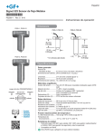
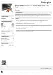
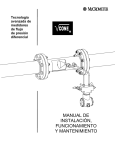
English
Signet 525 Metalex Flow Sensor
*P52590-1*
P52590-1
Rev. K
11/06
English
Maximum Operating Temperature/Pressure:
SAFETY INSTRUCTIONS
1. Do not remove from pressurized lines.
2. Do not exceed maximum temperature/pressure specifications.
3. Pipe fitting must be installed by certified welder only.
4. Do not install/service without following installation instructions
(see sensor manual).
5. Wear safety goggles and faceshield during installation/service.
6. Do not alter product construction.
7. Failure to follow safety instructions could result in severe
personal injury!
1. Location of Fitting
Flange
Recommended sensor
upstream/downstream mounting
requirements.
Inlet
10 X I.D.
Outlet
5 X I.D.
Valve/Gate
Signet 525 Metalex Sensor with:
• Signet 526-1XXX Series Saddle Fitting: 21 bar
@ 66°C (300 psi @ 150°F)
• Signet 526-2XXX Series Tee and Mini-Tap
Fitting: 103 bar @ 149°C (1500 psi @ 300°F)
Reducer
90° Elbow
15 X I.D.
5 X I.D.
5 X I.D.
40 X I.D.
5 X I.D.
2 x 90° Elbow
2 x 90° Elbow
50 X I.D.
20 X I.D.
5 X I.D.
25 X I.D.
5 X I.D.
2. Sensor Mounting Position
•
Horizontal pipe runs: Mount sensor in the upright (0°) position
for best overall performance. Mount at a maximum of 45° when
air bubbles are present. Do not mount on the bottom of pipe
when sediments are present.
•
Vertical pipe runs: Sensor must be mounted in lines with
UPWARD flow only.
45
45
3. Sensor/Fitting Selection
Wetted fitting materials:
316 SS
The 525 is designed for installation into SCH 40 stainless steel pipes
via Signet Metalex Tee, Mini-Tap or Saddle fittings, see options below:
Signet Metalex Tee Fittings (Sensor PN P525-1/-1S)
Pipe (in.)
Fitting
Code
0.50
P526-2005
198 840 501
0.75
P526-2007
198 840 502
1.00
P526-2010
198 840 503
Signet Metalex Mini-Tap Fittings (Sensor PN P525-2/-2S)
Pipe (in.)
Fitting
Code
1.25
P526-2012
159 000 494
1.50
P526-2015
198 840 506
2.00
P526-2020
159 000 495
2.50
P526-2025
159 000 496
3.00
P526-2030
159 000 497
4.00
P526-2040
159 000 498
5.00
P526-2050
159 000 499
6.00
P526-2060
159 000 500
8.00
P526-2080
159 000 501
10.0
P526-2100
159 000 502
12.0
P526-2120
159 000 503
+GF+
525-1
Sensor
(525-1S for Stainless Steel)
Tee Fitting,
hardware included
Wetted fitting materials:
316 SS & 347 SS
+GF+
525-2
Sensor
(525-2S for Stainless Steel Pin)
Mini-Tap Fitting,
hardware included
Signet Metalex Saddle Fittings (Sensor PN P525-3/-3S)
Pipe (in.)
Fitting
Code
2.00
P526-1020
159 000 484
2.50
P526-1025
159 000 485
3.00
P526-1030
159 000 486
4.00
P526-1040
159 000 487
5.00
P526-1050
159 000 488
6.00
P526-1060
159 000 489
8.00
P526-1080
159 000 490
10.0
P526-1100
159 000 491
12.0
P526-1120
159 000 492
Wetted fitting materials:
Ductile Iron, 347 SS,
Carbon steel,
Buna-N/Neoprene
+GF+
525-3
Sensor
(525-3S for Stainless Steel Pin)
Saddle Fitting,
hardware included
4. Fitting Installation, Required Hardware
Signet Metalex Tee & Mini-Tap Fittings, P525-2XXX
•
0.5 to 1 inch pipes, P526-2 series fitting required
•
1.25 to 12 inch pipes: P526-2 series fitting and 27 mm
(1-1/16 in.) diameter drill required
•
Mini-Tap fittings are welded onto the pipe and are used with
Signet 525-1 sensors.
Signet Metalex Saddle Fitting, P526-1XXX
•
27 mm (1-1/16 in.) diameter drill required
•
Weld pipe into place
Signet Mini-Tap Fittings, 1.25 to 12 inch:
•
Drill a 27 mm (1-1/16 in.) diameter hole completely through
the ONE surface of the pipe. Thoroughly deburr inner and
outer edges of hole.
•
Tack weld the Mini-Tap fitting onto the pipe, making sure the
hole in the pipe is lined up with the Mini-Tap fitting hole.
•
Weld the Mini-Tap fitting onto the pipe.
Signet Tee Fittings, 0.5 to 1 inch:
•
Insert pipe into fitting socket
•
Make sure the pipe is parallel to the bottom of the Mini-Tap
fitting.
4.2 Installation, Saddle Fittings
1. Select an appropriate mounting location as outlined in
sections 1 and 2.
2. Drill a 27 mm (1-1/16 in.) diameter hole completely through
the TOP surface of the pipe. Thoroughly deburr inner and
outer edges of hole.
1
4
3. Place the Buna-N/Neoprene saddle
O-ring over the pipe hole (small hole
U-bolt
side towards pipe). Position the saddle torque
fitting over the O-ring, making sure the pattern
O-ring centers on the underside fitting
3
2
ridge. Center saddle fitting and O-ring
over the pipe hole, then strap the fitting
to the pipe with the two U-bolts. Snug all four nuts in a crisscross pattern. Using a torque wrench (when possible) torque
the U-bolts in a criss-cross pattern to 52 foot-pounds.
5. Sensor Installation
6. Sensor Wiring
Saddle type fittings are strapped to the pipe and are used with
Signet 525-3 sensors. Welds MUST be made by a certified
welder who is licensed to weld stainless steel and other highcarbon grade steels.
4.1 Installation, Tee & Mini-Tap Fittings
1. Select an appropriate mounting location as outlined in
sections 1 and 2.
2. Depressurize and drain pipe.
3. Use the following welding and installation procedures
appropriate for your fitting/pipe size:
1.
2.
Set the gasket supplied with the fitting onto the fitting flange,
making sure the holes align.
Remove the red rotor protection cap and insert the sensor
into the fitting, making sure not to bump the rotor assembly.
Make sure the arrow on the side of the sensor is pointing in
the direction of flow.
Fitting
flange
1/2 in. NPT
conduit port
black
(AC signal out)
Flow sensor
arrow
525
4
Slip two washers onto each bolt and insert the bolt/washer
onto each of the four fitting flange holes.
Snug all four flange bolts in a criss-cross pattern. Using a
torque wrench (when possible), torque the flange nuts in a
criss-cross pattern to 52 foot-pounds.
1
4
Flange
bolt torque
pattern
3
2
Shld.
red
(AC signal out)
Flow
3.
Blk
FRed
F+
silver
(ground)
Instruments
Use 2-conductor shielded cable for cable splices to 60 m
(200 ft)
Maintain cable shield through splice.
Shield the unjacketed silver (ground) wire using electrical
tape to prevent potential noise interference and/or shorting
hazards.
Signet Intelek-Pro, use 525 input card setting.
2
Signet 525 Metalex Flow Sensor
7. Sensor Removal Procedure
1.
Depressurize and drain pipe.
2.
Remove the four sensor flange bolts and lockwashers. Pull
upward on the sensor flange with an alternating twisting
motion.
WARNING!
Do not remove from pressurized lines.
Wear safety goggles and faceshield
during installation/service.
8. Maintenance
The 525 sensor requires little or no maintenance of any kind, with the exception of an occasional sensor/paddlewheel cleaning.
9. Rotor Replacement Procedure
1.
2.
Remove retainer from each side
by gently tapping it inwards using
a punch. Install a new retainer
with its rotor pin clearance hole
inward. Only install one retainer
at this time.
3.
Rotor Pin
With a small pair of needlenose pliers, firmly grip the
center of the rotor pin (axle)
and with a twisting motion,
bend the rotor pin into an
"S" shape. This should pull
the ends of the pin out of the
retainers and free the rotor
assembly.
Retainer
Punch
4.
Insert the new rotor
assembly and bearings
into the rotor housing of
the sensor and place the
new rotor pin (axle) through
the open end of the rotor
housing, through the rotor
and bearings, and into the
previously installed retainer.
Rotor Pin
Existing
Retainer
New
Bearings
Rotor
Assembly
Tap the second retainer (rotor
pin clearance hole inwards)
into the hole while lining up the
rotor pin with the center of the
retainer hole. This completes
the rotor replacement
procedure.
10. K-Factors
The K-Factor is the number of pulses the sensor will generate for each engineering unit of fluid which passes. They are listed in U.S.
gallons and in liters. For example, in a 1 inch SCH 40S stainless steel pipe, the sensor generates 266.17 pulses per gallon of fluid
passing the rotor. K-Factors are listed for SCH 40S stainless steel pipes up to
12 inch.
SCH 40S STAINLESS STEEL PIPE PER ANSI B36.19
Conversion Formulas
1 U.S. gallon = 0.003785 cubic meters
0.000003069 Acre feet
8.3454 pounds of water
Signet 525 Metalex Flow Sensor
PIPE
SIZE
1/2 IN.
3/4 IN.
1 IN.
1 1/4 IN.
1 1/2 IN.
2 IN.
2 1/2 IN.
3 IN.
4 IN.
5 IN.
6 IN.
8 IN.
10 IN.
12 IN.
K-FACTOR
PULSES/
U.S. GAL
K-FACTOR
PULSES/
U.S. LITER
A-FACTOR
GPM/Hz
A-FACTOR
LPM/Hz
873.03
515.41
266.17
148.84
107.98
64.808
44.685
28.579
16.302
10.237
7.0057
3.9641
2.4690
1.6894
230.66
136.17
70.322
39.324
28.528
17.122
11.806
7.5506
4.3070
2.7046
1.8509
1.0473
0.6523
0.4463
0.0687
0.1164
0.2254
0.4031
0.5557
0.9258
1.3427
2.0994
3.6805
5.8611
8.5645
15.136
24.301
35.516
0.2601
0.4406
0.8532
1.5258
2.1032
3.5042
5.0822
7.9464
13.931
22.184
32.416
57.289
91.981
134.43
3
11. Specifications
General Data
Flow velocity range:
Frequency output:
Linearity:
Repeatability:
Pipe size range:
Cable length:
Cable type:
Wetted Materials
Sensor body:
Rotor material:
Rotor pin:
Retainers (2):
Rotor bearings (2):
Electrical Data
Voltage output:
Coil resistance:
Coil inductance:
0.5 to 6 m/s (1.6 to 20 ft/s)
29 to 46 hz per m/s (9 to 14 hz per ft/s)
(depending on pipe size)
±1% of full range
±0.5% of full range
13 to 305 mm (0.5 to 12 in.)
7.6 m (25 ft), can splice to 60 m (200 ft.)
with no significant degradation of signal
strength
150°C 22 AWG, 2-conductor w/shield
ACI type CF-8M (316 cast stainless steel)
per ASTM A351
CB7Cu-1 Alloy
Tungsten Carbide GRP 1 (standard);
316 stainless steel (optional)
316 stainless steel
Fluoroloy B®
Ambient Conditions
Maximum Pressure/Temperature Limitations:
Signet 525 Metalex Sensor with:
•
Signet 526-1 Series Saddle Fitting:
21 bar @ 66°C (300 psi @ 150°F)
Signet 525 Metalex Sensor with:
•
Signet 526-2 Series Tee or Mini-Tap Fitting:
103 bar @ 149°C (1500 psi @ 300°F)
Approximate sine wave, 0.005 to 0.008
Vp-p per Hertz
11.6 kW @ 25°C
3.5 Henrys @ 25°C
retainer
Mfr. Part No. Code
P525-1
P525-2
P525-3
P525-1S
P525-2S
P525-3S
Quality Standards
•
CE, FM
•
Manufactured under ISO 9001
198 801 494
198 801 495
198 801 496
159 000 963
159 000 964
159 000 965
rotor pin
retainer
bearing
bearing
rotor
P52509/P52509-2 Rotor kit
Accessories and Replacements Parts
Mfr. Part No.
Code
Description
P52509
P52509-2
P52504-1
P52504-2
P52618
P52503
P52527
P52628
P51589
5523-3222
198 801 501
159 000 480
198 801 500
198 820 023
159 000 493
198 820 013
159 000 481
159 000 504
159 000 476
159 000 393
Rotor kit w/Tungsten Carbide pin Fluoroloy-B bearings, 316 ss retainers
Rotor kit w/Tungsten Carbide pin Fluoroloy-B bearings, 316 ss retainers
Rotor Pin, Stainless steel (optional)
Rotor Pin, Tungsten Carbide (standard)
Gasket
Bearing, Fluoroloy B®
Retainers, Stainless steel
Fitting cap kit (cap and gasket)
Conduit Adapter Kit
Cable (per foot) 2 cond. w/shield, 22 AWG
George Fischer Signet, Inc., 3401 Aerojet Avenue, El Monte, CA 91731-2882 U.S.A. • Tel. (626) 571-2770 • Fax (626) 573-2057
For Worldwide Sales and Service, visit our website: www.gfsignet.com • Or call (in the U.S.): (800) 854-4090
P52590-1 Rev. K 11/06 English
© George Fischer Signet, Inc. 2002
Printed in U.S.A. on recycled paper