1
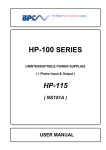
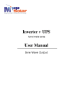
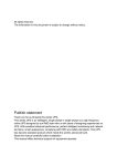
Table of Contents Introduction .................................................................................................... 2 Important Safety Information (Be Sure to Read)............................................ 3 1. Overview ................................................................................................... 5 1.1 L2 Series............................................................................................... 5 1.2 Front Panel ........................................................................................... 6 2. Installation ................................................................................................ 7 2.1 Placement ............................................................................................. 7 2.2 Back Panel ............................................................................................ 8 2.3 Connection (for the model with connection terminal) ............................... 9 2.4 Communication with PC......................................................................... 9 3. Operation ................................................................................................ 10 3.1 Switching On ....................................................................................... 10 3.2 Switching Off ....................................................................................... 12 3.3 Operation Modes ................................................................................. 13 3.4 Indicators ............................................................................................ 14 3.5 Automatic Battery Test......................................................................... 15 3.6 Overload ............................................................................................. 15 3.7 Audible Warnings ................................................................................ 15 3.8 Settings Menu ..................................................................................... 16 4. Troubleshooting...................................................................................... 18 5. Maintenance ............................................................................................ 19 6. Technical Specifications......................................................................... 20 L2 2-3kVA V1.0.1 – Page | 1 Introduction Thank you for choosing our Uninterruptible Power Supply product for protection of your electrical devices. The L2 Series Uninterruptible Power Supply (UPS) was manufactured using the latest technology. We recommend you to read this manual to learn many specifications and superior features of your new UPS. We do pay attention to the environmental impacts of this product. Example of some of our measures to protect environment are as follows: Product design is based on economical size and high efficiency approach. Quality and uninterruptible power is provided without distorting source voltage. Manufacturing is carried out in our ISO 14001:2004 Environment Management System certified factory. It is ensured that battery and metal wastes are disposed properly. To discover the entire range of our products and to receive up-to-date information, please visit our web site: ……………..……………………........................ Before you call us… If you require assistance for a failure or any related issues, call our Technical Support Center. For quick assistance, please have the following information available. Model Power (KVA) Serial Number Purchase Date Installation Date Mains Voltage/Frequency Battery Quantity x Ah Company L2 Series ……………………………… ……………………………… ……………………………… ……………………………… ……………………………… ……………………………… ……………………………… The L2 Series products are protected under a patent. Therefore, implementation of our proprietary technology by competitors is not permitted. Given the relevant standards and technology, device hardware configuration may be changed without notice. Technical specifications and dimension information are not binding unless formally confirmed by us. Page | 2 – L2 2-3kVA V1.0.1 Important Safety Information (Be Sure To Read) Life Safety Use UPS in an access-restricted room (EN 62040-1-2). The UPS has its own power source (batteries). Therefore, there may be live power at the output even if the mains voltage is disconnected. There is dangerous level of voltage in the UPS, and it must be opened by an authorized service personnel only. The UPS must be grounded in adherence to the rules. Do not expose batteries to extreme high temperatures to prevent fire risks. Do not attempt to open the battery. Chemical composition of the battery may be dangerous for your skin and eyes. Adhere to all regulations that govern disposal of waste batteries. Safe Handling Be careful while carrying loads. Do not carry heavy loads without help. Slide roller devices on smooth and even surfaces. Do not use slopes with angles over 10°. Adhere to following recommendations about load weights. An adult can carry loads up to 18 kg weight. Two adults can carry loads up to 32 kg weight. Three adults can carry loads up to 55 kg weight. Use pallet jack, forklift or similar devices for carrying loads over 55 kg weight. Keep packaging material for use in case the UPS has to be transported to an authorized service or to another location. UPS Safety The UPS must be safeguarded against voltage overload or short circuit voltages by means of a readily accessible circuit breaker. Do not operate the UPS at environment temperatures or relative humidity that exceeds the limits given in the manual. Never operate the UPS in liquid environments or in overly humid environments. Never allow water or foreign substances to penetrate in the UPS. Strictly do not clog ventilation grids of the UPS. Never expose the UPS to direct sunlight or a direct heat source. The UPS’ useful life is 10 years. L2 2-3kVA V1.0.1 – Page | 3 Special Safety Information UPS’ electrical connections must be provided as shown in the manual. Be sure to check the compatibility of the UPS power to mains voltage and to total load that will be supplied with UPS. UPS must be stored in a dry environment between -10°C and 45°C temperature prior to commissioning. UPS must be operated at least once a month continuously for 24 hours to charge the batteries. Because the battery life commences on the manufacture date, storage life is limited. UPS is designed to operate at height, operating environment temperature, relative humidity rate, and handling and storage conditions described in UPS manual. Special design and protection measures are essential for non-normal operating conditions. Such non-normal operating conditions include: - Harmful fume, dust, abrasive dust; - Humidity, vapor, bad weather, frost; - Explosive dust and gas mixtures; - Extreme temperature changes; - Poor ventilation; - Exposure to direct or radiated temperature from other sources; - Intensive electromagnetic fields and harmful radioactive levels; - Insects, pests, fungus, etc. Change and Recycling of Batteries Battery poses electric shock hazard and short circuit risks. Replace only with batteries of same type, capacity, number and dimensions. Battery replacement must be carried out by trained service personnel only. Remove metal accessories such as wristwatch, ring, etc. and wear rubber shoes and gloves to prevent accidents and personal injury. Use tools with isolated handles. Make sure that battery connections are not grounded by mistake. Do not leave tools or metal pieces on batteries. Batteries must be recycled. Return mutilated batteries to any recycling facility or to company where you initially purchased them along with packaging material of new batteries. UPS must be installed in strict adherence to following standards: HD 384.4.42 S1: Electrical Installation in Buildings, Chapter 4: Safety Protection Group 42: Protection Against Thermal Effects HD 384.4.482.S1: Electrical Installation in Buildings, Chapter 4: Safety Protection Group 48: Choosing Protective Measures Against External Effects – Section 482: Fire Protection in Places Bearing Special Risks or Dangers Page | 4 – L2 2-3kVA V1.0.1 1. Overview 1.1. L2 Series UPS Cabin Dimensions UPS Power (W/VA) 1400/2000 2100/3000 Backup Time (min) (100% load/50% load) 0/0 1/2 2/4 3/7 4/11 Width x Height x Depth (mm) 175 x 265 x 485 Net Weight (kg) 2KVA 3KVA 15 17 23 25 27 21 23 25 Figure 1.1 UPS Cabin Table 1.1 UPS Cabin Dimensions and Weights External Battery Cabin (optional) Dimensions Width x Height x Depth (mm) 175 x 265 x 485 Backup Time (min) (100% load/50% load) 0/0 4/11 7/21 12/34 18/53 22/63 34/94 Net Weight (kg) (UPS Cabin/External Battery Cabin) 2KVA 3KVA 15/9 17/9 17/26 15/26 17/29 15/29 17/39 27/39 15/39 25/39 Figure 1.2 External Battery Cabin Table 1.2 External Battery Cabin Dimensions and Weights L2 2-3kVA V1.0.1 – Page | 5 1.2. Front Panel Figure 1.3 Front Panel No. INDICATOR Explanation 1 BATTERY 2 LOAD This shows the remaining battery life in percentage. This shows the percentage of power utilized by loads connected to output in comparison to total UPS output capacity. No. 3 LED On Off OVERLOAD See: ‘3.6 Overload’ UPS is loaded 0% to 100%. UPS is operating on battery. See: ‘3.7 Audible Warnings’ Mains voltage is at least 10% lower than normal voltage. Mains voltage is within the tolerance limits. Mains voltage is at least 10% greater than normal voltage. UPS is not operating on battery. 4 INVERTER 5 FAULT 8 LOW 9 NORMAL 10 HIGH No. BUTTON 6 ON 7 OFF >3 seconds (Press and hold longer than 3 seconds) Switch On (when fully switched off) Switch off fully No malfunction or warning. Mains voltage is within the tolerance limits. Mains voltage is out of tolerance limits. Mains voltage is within the tolerance limits. <3 seconds (Press less than 3 seconds) On (If output is off) Turn on/off audible warning Turn off output Table 1.3 Front Panel Operation Page | 6 – L2 2-3kVA V1.0.1 2. Installation 2.1. Placement UPS Placement Do not install the UPS on an uneven ground or in outdoors. Do not install the UPS in places where it will be exposed to direct sunlight or affected of heat sources. Heed to minimum distance requirement between the UPS and nearby walls and/or devices. Do not install the UPS in places where it may be subject to vibration or impacts. Do not operate the UPS in dusty or filthy environments. Note that ventilation holes on side covers must not be clogged. Do not install the UPS in places with liquid installation or places subject to fire risks. Do not install the UPS in environments with excessive (too high or too low) humidity levels. Do not leave any materials on or around the UPS to facilitate and expedite maintenance and repair operations. The UPS may overheat if distance requirements are not met. Moreover, this may complicate maintenance and repair operations. The UPS must be installed in a room with restricted access (Authorized Personnel Only). External Battery Cabin Placement Heed to UPS placement instructions when placing the external battery cabin. L2 2-3kVA V1.0.1 – Page | 7 2.2. Back Panel Figure 2.1 Back Panel (Check back panel that corresponds to model you have chosen) No. Part Function This ensures that the UPS can be monitored using a computer software. This is used to protect UPS against overload and short-circuit. 1 RS232 Port 2 Input Fuse 3 Input Socket This is the socket for mains connection. 4 Output Sockets These are the sockets for load connections. 5 Fan(s) These are used for cooling the UPS. 6 Contact Cover This is used to prevent the contact with live contacts. 7 External Battery Cabin Contacts (on the cabin) This is where cable connections are made if (optional) external battery cabin is used. Table 2.1 Back Panel Operation Page | 8 – L2 2-3kVA V1.0.1 2.3. Connection (for the model with connection terminal) Figure 2.2 Connection Terminals No. 1 Connection Terminal BATTERY (External Battery Cabin) 2 INPUT 3 OUTPUT BAT (+) E3 BAT (-) (+) pole Earth (-) pole IN R IN N1 E1 R-phase Neutral Earth OUT U OUT N2 E2 U-phase Neutral Earth Table 2.2 Connection Terminal Operation 2.4. Communication with PC You can monitor the UPS over RS232 port using UPSilon2000 software that you will install on your computer (this is optional and therefore UPS software and RS232 cable must be ordered prior to use of this option). Using this software, you can monitor realtime UPS voltage and current information, battery information, malfunctioning warnings, etc. and save long term logs with graphics. In addition, software shuts down your computer and/or server safely in case of any electrical power outage. Figure 2.3 RS232 Communication L2 2-3kVA V1.0.1 – Page | 9 3. Operation 3.1. Switching On 1. Switching on mains voltage: a. For models with patch cable: Firstly, plug in the patch cable to mains socket (Figure 3.1), later plug it in to input socket (Figure 3.2). For models with terminals: Make sure that cable connections were provided appropriately. Figure 3.1 Figure 3.2 b. Press ON button until an audible warning is heard, meanwhile observe that NORMAL LED is turned on (Figure 3.3). Along with audible warning, all LED lights flash and UPS starts up. Observe that battery indicator LED lights are on and briefly press ON button (Figure 3.4). Figure 3.3 Figure 3.4 c. If mains voltage and mains frequency are within the limits, NORMAL LED will be on constantly (Figure 3.5), if they are out of limits, NORMAL LED will not turn on (See: Starting on Battery). At this stage, you can connect your loads to output sockets (for models with patch cable) (Figure 3.6) or turn on your loads connected to UPS output (for models with contact). Figure 3.5 Page | 10 – L2 2-3kVA V1.0.1 Figure 3.6 2. Cold Start: a. The UPS has Cold Start feature. It means that the UPS can be started on battery without mains connection. Press ON button until an audible warning is heard, meanwhile observe that NORMAL LED is turned on (Figure 3.7). Along with audible warning, all LED lights will flash and UPS will start up. Observe that battery indicators LED lights are on and press ON button briefly (Figure 3.8). Figure 3.7 Figure 3.8 b. Following 2 consecutive audible warnings, INVERTER LED will turn on (Figure 3.9). At this stage, you can connect your loads to output sockets (for models with patch cable) (Figure 3.10) or turn on your loads connected to UPS output (for models with contact). Figure 3.9 Figure 3.10 The UPS will also start up on battery in cases where –although a mains connection is available, mains voltage and/or mains frequency is out of tolerance limits. L2 2-3kVA V1.0.1 – Page | 11 3.2. Switching Off 1. If UPS is in Normal Operation Mode: Turn off your loads safely. Briefly press OFF button (Figure 3.11) and observe that NORMAL LED turns off. Press and hold OFF button until audible warning silences (Figure 3.12) and observe that battery indicator LED lights turn off. Figure 3.11 Figure 3.12 Before fully switching off the UPS operating in normal mode, switch off the output by briefly pressing OFF button. When disconnecting cable connection of models with patch cable, remove input socket first and later the mains socket (Figure 3.13). Figure 3.13 2. If UPS is in Battery Operation Mode: Turn off your loads safely. Briefly press OFF button and observe that INVERTER LED turns off (Figure 3.14). Press and hold OFF button until audible warning silences and observe that battery indicator LED lights turn off (Figure 3.15). Figure 3.14 Figure 3.15 Before fully switching off the UPS operating in battery mode, switch off the output by briefly pressing OFF button Page | 12 – L2 2-3kVA V1.0.1 3.3. Operation Modes L2 Series has Line-Interactive UPS technology. When mains voltage and mains frequency are within the tolerance limits, UPS performs Automatic Voltage Regulation (AVR) and over current protection, transfers the mains voltage to loads and meanwhile charges the batteries. When mains voltage and/or mains frequency are out of tolerance limits, UPS begins supplying loads with battery power (discharge). Switching to battery operation will not be sensed by the loads. Thanks to its Automatic Voltage Regulation (AVR) feature, L2 Series is able to reduce/increase voltage transferred to output by 15% when mains voltage increased/decreased at percentages between 10% to 25%. If mains voltage is greater or less than normal voltage by more than 25%, UPS begins supplying loads from battery. L2 Series UPS has following operation modes. Figure 3.16 Mains Interactive UPS Operation Principle Normal Mode Mains voltage is fed through filter and Automatic Voltage Regulation (AVR) units and transferred to output via transfer switch. Meanwhile, battery charger unit charges batteries with voltage supplied from input unit. Battery Mode Battery charger and Automatic Voltage Regulation (AVR) units does not operate. Inverter unit generates appropriate voltage by discharging battery power. Generated voltage is transferred to output via output switch. Sleep Mode This operation mode ensures that battery capacity is used efficiently and battery life is maintained. UPS operates on Sleep mode in following cases: a. When the UPS is connected to mains, it begins operating in Sleep mode. Batteries are charged even if the UPS is not switched on. b. When the load percentage is less than 5% during battery mode, the UPS will switch off the output and switch to Sleep mode. Output switch off when load percentage is less than 5% during battery operation can be cancelled (See: ‘3.8 Settings’). L2 2-3kVA V1.0.1 – Page | 13 c. When the battery capacity is 0%, the UPS will switch off the output and switch to Sleep mode. Once mains voltage and mains frequency are within the tolerance limits again, UPS will begin running in normal mode automatically. 3.4. Indicators Battery Indicator Remaining Battery Capacity LED Display Between 0% and 25% Between 26% and 50% Between 51% and 75% Between 76% and 90% More than 91% Figure 3.1 Battery Indicator Table Load Indicator Loading Ratio LED Display Between 0% and 9% Between 10% and 25% Between 26% and 50% Between 51% and 75% Between 76% and 95% More than 96% Figure 3.2 Load Indicator Table Page | 14 – L2 2-3kVA V1.0.1 Battery indicator’s 0%-25% LED and capacity used indicator’s more than 96% LED are red and indicate that the device is at dangerous operation limits. 3.5. Automatic Battery Test The UPS self diagnoses the batteries by running on battery automatically at every 30 days. The testing process is run when UPS is in normal operation mode. At the end of the test, the condition of the batteries (usable or not) is provided. When the Battery Test is negative, please contact with the Technical Service. ‘The ‘Automatic Battery Test’ may also be run after long power outages. In this case the ‘Battery Failure’ test result should be disregarded. An ‘Automatic Battery Test’ on batteries charged for at least 10 hours should be regarded. 3.6. Overload During overload; UPS may run in normal operating conditions for below defined-periods. UPS shuts the output when the below defined periods are exceeded. Loading Ratio (%) 100-110 110-125 125-150 >150 Power (VA) 2000 3000 2000-2200 3000-3300 2200-2500 3300-3750 2500-3000 3750-4500 >3000 >4500 Running Time 30 minute 60 seconds 10 seconds 3 seconds Table 3.3 Overload Table 3.7. Audible Warnings Subject Audible Warning Battery 2 times consecutively in 60 seconds Constant Warning Info Operation on Battery Battery Low Constant Battery Malfunction Overload Constant Overload (See: ‘3.4 Overload’) Error/Failure Constant Over temperature, Battery High, Over Current, Output Fault Table 3.4 Audible Warnings Table L2 2-3kVA V1.0.1 – Page | 15 3.8. Settings Menu The UPS has a settings menu where Mains Frequency, Mains Voltage, Sleep Mode and Battery Charging Current settings can be changed. This menu consists of the following: Mains Frequency: Mains frequency options are 50Hz and 60Hz. Mains Voltage: Mains voltage options are 220VAC, 230VAC and 240VAC. Sleep Mode: Sleep Mode options are On and Off. Battery Charging Current: Battery charging current options are 0.7A, 2A, 4A, 6A and 10A. The UPS must be connected to mains and must be fully switched off before entering to Settings Menu. Press and hold OFF button until an audible warning is heard, meanwhile observe that NORMAL led turns on (Figure 3.17). Along with the audible warning, INVERTER led, load and battery indicators first step led lights will turn on (Figure 3.18) (if the mains frequency is 50Hz) and UPS will start up. Load indicator led can be progressed by pressing ON button and battery indicator LED can be progressed by pressing OFF button until desired settings achieved. Figure 3.17 Figure 3.18 Page | 16 – L2 2-3kVA V1.0.1 VOLTAGE FREQUEN CY SETTINGS MENU LED DISPLAY LOAD INDICATOR BATTERY INDICATOR 50Hz 60Hz 220VAC 230VAC BATTERY CHARGING CURRENT SLEEP MODE 240VAC ON OFF 0.7A 2A 4A 6A 10A Table 3.3 Settings Table Settings menu must be used by authorized personnel only. Please contact our Technical Support Center for detailed information. L2 2-3kVA V1.0.1 – Page | 17 4. Troubleshooting Make sure you go through the table below before contacting the Technical Service. Cable connections and fuse checks must be performed by authorized personnel only. UPS is not turned on and the lights are not lit UPS operates on battery constantly Error LED is on and UPS is constantly emitting audible warning Possible Failure ON button is pressed too shortly. Batteries run out fully. Mains voltage and/or frequency is out of limits. Fuse blown. Problem with patch cord connections. Contact the Technical Service. Mains voltage and/or frequency is out of limits . Fuse blown. Problem with mains connection. Contact the Technical Service . ‘Battery Failure’ warning Solution Press and hold ON button for at least 3 seconds. UPS must be connected to mains. Mains voltage and frequency must be checked. Press the fuse inwards (Figure 4.1). Battery connections must be checked. Mains voltage and frequency must be checked. Press the fuse inwards (Figure 4.1). Mains connection must be checked. See: ‘3.5 Automatic Battery Test’. ‘Over-current’ warning Check UPS loading ratio and environment temperature. Switch off UPS and wait for a while. Switch UPS off and on again. ‘Output Fault’ warning Switch UPS off and on again. ‘Overheat’ warning. ‘Battery High’ warning Contact the Technical Service . Overload LED is on and UPS is constantly emitting audible warning ‘Overload’ warning Check loading ratio. Reduce loads connected to UPS output. Battery operation time is too short Batteries are not fully charged Battery charger or batteries are malfunctioned. Try again once batteries are charged for at least 8 hours. Contact the Technical Service. Table 4.1 Troubleshooting Table Figure 4.1 (See the one that corresponds to model you have chosen) Page | 18 – L2 2-3kVA V1.0.1 5. Maintenance The UPS should only be opened by authorized personnel. The UPS must be completely off during maintenance. Mains and battery connections must be disconnected and batteries must be moved away from the UPS. Follow the ‘Important Safety Information’ and ‘Installation’ instructions during the maintenance. The electronic boards and the fans should be cleaned regularly. The ventilation holes on the lid should be cleaned regularly. The UPS body should be cleaned with a soft and moist cloth. The sturdiness of cable connections, screws and sockets should be checked. The board supply voltages should be measured and checked. The components on the boards and the other hardware should be checked. The voltages of the batteries should be checked by measuring the voltages separately. The accuracy of the calibration and the adjustments should be checked. The dust, the heat and the temperature in the UPS room should be checked. The instructions in the ‘Important Safety Information and Installation’ should be complied. L2 2-3kVA V1.0.1 – Page | 19 6. Technical Specifications TECHNICAL SPECIFICATIONS L2 SERIES 2 Power (KVA) 3 INPUT Voltage 220 / 230 / 240 Vac Voltage tolerances -25% / +20% Frequency 50 / 60 Hz (Auto detect) Frequency tolerances ± 10% OUTPUT (on mains) Voltage 220 / 230 / 240 Vac Voltage tolerances ± 10% Frequency 50 / 60 Hz Frequency tolerances ± 10% OUTPUT (on battery) Voltage 220 / 230 / 240 Vac (sine wave) Voltage tolerances ± 2% Frequency 50 / 60 Hz (selectable) Frequency tolerances ± 0.1% Power factor 0.7 THDv ≤ 3% (linear load) Crest factor 3:1 OVERLOAD CAPACITY 110% 30 min. 125% 60 sec. 150% 10 sec. > 150% 3 sec. GENERAL Technology Line-interactive Control Microprocessor Communication SNMP(Optional), RS232 Transfer time < 5ms Remote monitoring SNMPView, UPSilon Cold start Standard ENVIRONMENT Operating temperature from 0 °C up to +40 °C (from 20 °C to 25 °C for maximum battery life) Relative humidity 0% - 85% (without condensation) Maximum altitude ≤ 2000 m Noise level < 45 dB (A) UPS CABINET Dimensions (W x D x H) 175 x 485 x 265 (mm) Weight (kg) 15 17 Degree of protection IP20 Colour RAL7012 BATTERY CABINET Internal battery quantity 4 Internal battery capacity 7-9 (Ah) External battery cabinet Standard socket STANDARDS Safety EN 62040-1 EMC EN 62040-2 UPS LIFETIME 10 years ELEN reserve the right of changing information in this without report. Page | 20 – L2 2-3kVA V1.0.1 AUTHORIZED TECHNICAL SERVICE L2 2-3kVA V1.0.1 – Page | 21