1
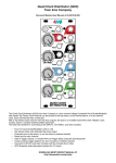
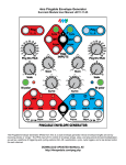
QCD Expander
from 4ms Company
Eurorack Module User Manual
The QCD Expander from 4ms Company is an expansion module for the Quad Clock Distributor (QCD). The QCD
Expander requires the QCD to function, and adds a host of features. The Expander turns the QCD into a
programmatic non-linear sequencer, easily obtaining self-patched evolving rhythms, and swing/shuffle patterns.
Each of the four channels has:
• Multi-mode output jack INV OUT mirrors the tempo of main QCD output
• Mode Switch for each INV OUT jack:
◦ Delayed Trigger Mode
◦ Inverted Gate Mode
◦ Shuffle Mode (delayed + original trigger)
• PW/Delay knob controls trigger delay time on INV OUT jack (or pulse width in Inverted Gate Mode)
◦ Also controls Pulse Width of main QCD OUT jack
◦ CV input jack for external control
◦ Attenuverter allows for one channel to precisely modulate another channel's delay or pulse width
• Div/Mult CV attenuator knob
◦ Controls how much the signal on the main QCD's Div/Mult CV jack will modulate the tempo
◦ Useful for precisely modulating the speed of one channel with another
A global LED brightness trimpot is accessible from the front panel.
DOWNLOAD MOST RECENT MANUAL AT:
http://4mspedals.com/qcd.php
Basic features:
•
•
•
Connects to QCD module with a 16-conductor ribbon cable (included)
When connected to a QCD, the following features are added to each QCD channel:
◦ Multi-mode clock output (INV OUT) is the same tempo as the QCD's OUT jack
◦ Switch for selecting mode of the INV OUT jack:
▪ Delayed Trigger mode (left)
▪ Inverted Gate mode (center)
▪ Shuffle mode = delayed + original trigger (right)
◦ Knob for controlling amount of trigger delay, as well as pulse width of the main QCD output
◦ CV jack for controlling trigger delay and pulse width using another channel or external CV
◦ Attenuverter knob for Gate PW/Trig Delay CV jack (controls the amount the signal on the jack effects the
PW/Delay)
◦ Attenuverter knob for Div/Mult CV jack (on the main QCD module)
LED brightness can be adjusted from the front panel
Controls and jacks:
• INV OUT jack (each channel)
• +5V trigger (10ms) or +5V gate output. See Mode Switch, below
• Runs at the same Div/Mult tempo as the main QCD output, but may be delayed, inverted and/or shuffled.
• Three-position Mode Switch (each channel)
• Only effects the INV OUT jack on the Expander (no effect on the main QCD output)
• Left = Delayed Trigger mode
• Center = Inverted Gate mode
• Right = Shuffle mode (delayed + undelayed), effectively doubles the tempo
• Trigger Delay (Pulse Width) big knob, attenuverter, and jack:
• Depending on the Mode Switch, either trigger delay time or pulse width is controlled
• Pulse width of the main QCD output is always effected (no matter what mode the expander is in)
• The big knob sets the amount of delay time or pulse width
• The signal on the CV jack is variably attenuated and/or inverted using the attenuverter
• The attenuverted CV and big knob's setting are added together
• Attenuverter for Div/Mult CV
• Variably attenuates and/or inverts the signal on the Div/Mult CV jack on the main QCD module
• LED dimmer
• The small hole at the bottom is for adjusting the LED brightness. A tiny phillips screwdriver can be inserted
through the panel to adjust the brightness. See section later in the manual for details
Specifications
•
•
•
12 HP Eurorack format module
0.98” (25 mm) maximum depth
+12V rail: 44mA max, +5V rail not used, -12V rail: 30mA max
Connecting to the QCD
First, remove all the jumpers from the QCD's
"EXPANDER" header. Save these jumpers
with your QCD box and manual in the bag
provided with the QCD. You may wish to use
small needle-nose pliers to remove the
jumpers if you can't remove them with your
fingers.
Second, connect the QCD and QCD
Expander together using the 16-conductor
ribbon cable provided. One end plugs into
the "EXPANDER" header on the QCD, and
the other end plugs into the "TO QCD"
header on the QCD Expander. Make sure
the red stripe points down on both modules.
Now connect both modules to your power
rails, and power up. Tap a tempo on the
QCD, and the lights on the QCD Expander
should blink in time and change rate when
you turn the QCD's Div/Mult pot. Also, the
main QCD's lights should react to adjusting
the Gate PW knob on the Expander.
Note: The ribbon cable that connects the
QCD and QCD Expander is a standard
Doepfer/Eurorack power cable. In case you
lose or misplace the cable, or need a
different length, you can use a standard 16to-16pin Eurorack power cable.
About Attenuverters
“Attenuverter” is short for “attenuating inverter”. These knobs take the signal on the CV
jack and control how much of this signal will effect the parameter. They also can invert the
CV signal, meaning that a positive CV signal creates a negative effect (and vice-versa).
On the QCD and Expander, the two parameters with CV jacks and attenuverters are
Div/Mult and Gate PW/Trig Delay. The CV jack for Div/Mult is located on the main QCD
module, and the CV jack for PW/Delay is located on the Expander module. Both
attenuverters are located on the Expander.
When the attenuverter knob is turned to the center, the CV jack will have no effect on the
parameter. The knob has a slight detent at center, so this position can be easily found by
feel.
Turning the knob slightly to the right means that a positive signal on the CV jack will
increase the parameter slightly (for example, Div/Mult might sweep from “=” to x2). At fully
clock-wise, a 5V signal will sweep the parameter from half-way to maximum (for example Div/Mult would sweep from “=” to
x16). A 10V signal will sweep the parameter from minimum to maximum (/32 to x16).
Turning the knob slightly to the left means a positive signal will decrease the parameter slightly (for example, Div/Mult might
sweep from “=” to /2). At fully counter-clockwise, a 5V signal will sweep from half-way to minimum (e.g. “=” to /32).
When patching one QCD channel into another's Div/Mult CV jack, the channel will switch between two tempos. The first
tempo is set by the main Div/Mult knob. The second tempo is set by the Div/Mult CV attenuator. Turning the attenuator to the
right means the second tempo will be faster than the first. Turning the attenuator to the left means it'll be slower.
Making Rhythms
The QCD Expander and QCD are designed to create an infinite variety of rhythms that can be programmatically built, as
opposed to linearly "grid" sequenced. This is a form of non-linear sequencing. Using a few short patch cables, you can create
complex rhythmic patterns for multiple voices/drums.
The basic concept is to use the channels to modulate each other:
• Modulate a channel's Div/Mult amount with another channel. Use the Div/Mult CV attenuator knob to fine-tune.
• Modulate a channel's Trig Delay amount with another channel. Use the PW/Delay CV attenuator knob to fine-tune.
• Reset a faster channel with a slower channel.
• Use one channel to route other channels, using an external module such as a switch or VCA Matrix.
• Clock a channel with a dynamically changing channel to introduce clock tracking lag
Typically, the modulated channel will be faster than the modulating channel. For example, one channel might run at x2 and
the second channel running at /4 could modulate the first channel's Div/Mult between x2 and x3.
In the examples below, some references to drums (kick/snare/hats/etc) will be made. This is only to make
use of a common musical language and the relative tempos/spaces these drums traditionally fill in music.
That is, you don't actually need to imitate a particular type of acoustic instrument to enjoy the QCD! It's
great practice to Async trigger a PEG channel, or Reset trigger a QPLFO channel, or trigger an ADSR, and
use those shapes to modulate filters, VCOs, VCAs, wavetables, etc...
Example Rhythmic Patch# 1
This patch uses the black
channel to speed up and
slow down the red channel.
The black Div/Mult ( )
determines how quickly the
red channel changes from
fast to slow and back. The
black PW ( ) determines
how long it's fast vs. how
long it's slow. The red
Div/Mult ( ) determines
the slow speed, and the CV
attenuverter ( )
determines the fast speed.
After patching, we should
hear bongos speeding up
and slowing down and a
kick whenever the bongos
change tempo.
First, tap in a tempo. Plug Tap Out to trigger a "snare" or metronome.
Set red Div/Mult to anywhere between = and x3. Patch red INV OUT to trigger a "bongo" sound.
Set black Div/Mult to anywhere between /5 and /2. Patch black INV OUT to trigger a "kick" sound.
Patch black OUT to red Div/Mult CV.
Flip the black Mode Switch to the left to start. Try it later to the right, especially if black Gate PW is not centered.
Adjust red Div/Mult CV attenuverter knob slightly to the right. Hear how the red channel goes fast/slow? The amount it
goes faster will increase as you turn this knob to the right.
Adjust black Gate PW. To the left, the red channel will spend more time being slow. To the right, it'll spend more time
being fast.
Set red Mode Switch to the left or right. Try both and listen for the difference (more hits to the right). Adjust red PW/Delay
if you want to play with a timing offset
Now let's add some phase-shifting hi-hats. The blue channel is set to shuffle mode, and Trig Delay is modulated by a slow
LFO or envelope, making the shuffle amount change over time. The green channel is set to a slow rate and should reset,
ping, or trigger the external LFO/envelope.
First, patch blue INV OUT to trigger your "hi-hat" sound.
Set blue Div/Mult between = and x3. This is the base rate of the hats.
Flip blue Mode Switch right (shuffle).
Set blue Trig Delay (big knob) to about 10%. Play with the setting and hear how the shuffle pattern changes.
Set blue Trig Delay attenuverter to 100%. Try setting it lower for a more subtle phase modulation.
Set green Div/Mult to /16 or /32. Run Green OUT to ping or trigger a PEG or QPLFO, and run the output of that into the
Blue CV jack.
Optionally, instead of
you can run any slow LFO into the Blue CV jack. Then the Green channel can be used for a
different rhythm.
Example Patch #2: Juke Rhythm
This patch makes a traditional Juke or Trap beat pattern. There are many variations of this beat, but this is a versatile starting
point.
Tap a tempo, or run a master clock into Red CLK IN.
Kick:
Turn Red Div/Mult to /3. Run the Red main OUT to trigger a "kick" and/or a low "conga".
Turn Black Div/Mult to /8.
Patch Black OUT to Red Reset. The Juke kick comes from a /8 reseting a /3.
Hats:
Turn Blue Div/Mult to /2 or "=". Run the Blue QCD OUT to trigger your "hi-hats".
Flip Red Mode Switch to center (Inverted Gate mode).
Patch Red INV OUT to Blue Div/Mult CV. The Hats should be shifting tempo with the kick.
Adjust Blue Div/Mult CV attenuator carefully to get a good hats pattern. Try just a hair to the right of center.
Adjust the Red Gate PW, listening to how it changes the hats pattern.
Kick/conga pitch:
Turn Green Div/Mult to /32. Run the Green OUT to your kick drum patch to modulate the pitch every 4 bars.
Hint: Really you might want to run Green OUT into an RCD or another QCD, and use one of those outputs to modulate pitch.
This gives you more flexibility since the Green channel will also be tied to the Clap sound.
Flip Green Mode Switch to the right (shuffle)
Turn Green Trig Delay to 50%. Run INV OUT to trigger your clap sound.
You still have two INV OUT jacks not being used! Try patching them into other drum modulation points, or controlling an LFO
that sweeps some other parameter of the QCD...
Also, to add some spasticness, try patching the Blue INV OUT into the blue Reset jack. Adjust Blue Gate PW/Trig Delay to
control density.
Next, with a second QCD, RCD, and/or SCM, you can slowly change some of the QCD's parameters to create an evolving
beat. Just add a sampler, one vocal sample, and some footwork!
Mode Switch
Each channel has a mode switch located above the Div/Mult CV attenuator.
The Mode Switch only effects the INV OUT jack. It has no effect on the main QCD
output. The Mode Switch interacts with the Pulse Width/Trig Delay setting.
The switch has three positions: left, center, and right.
Left: Delayed Trigger mode
Center: Inverted Gate mode
Right: Shuffle Mode (delayed + original triggers)
Mode Switch: Left
Delayed Trigger Mode
Gate PW/Trig Delay sets delay time (percentage)
Delayed Trigger Mode:
Top trace (blue) is master clock
(shown as a trigger for emphasis).
Bottom trace (red) is Delayed Trigger.
PW/Trig Delay is at 50%.
The INV OUT jack will output a 10ms trigger delayed by a percentage (fraction) of
the beat's period. Delay time is set by the Gate PW/Trig Delay knob and CV. For
example, with the knob at 50% and no CV, the delayed trigger will happen after 50%
of the period has passed (on the up-beat). At 25%, the trigger will happen 25%
through the beat period.
Another way of looking at this mode is that a trigger will fire every time the main
QCD output falls from high to low (falling edge). Since pulse width is defined as the
amount of time between rising and falling edges, controlling the Pulse Width
changes the amount of delay between the rising edge and the (delayed) trigger.
Mode Switch: Center
Inverted Gate Mode
Gate PW/Trig Delay sets pulse width
The INV OUT jack will be an inverted copy of the main QCD output. The INV OUT
always ranges from 0V to +5V (positive voltage), so technically it's an inverted and
shifted gate output.
What this means is when the main QCD output goes high from 0V to +5V, the INV
OUT goes low from +5V to 0V, and vice-versa.
Inverted Gate Mode:
Top trace (blue) is main QCD OUT.
Bottom trace (red) is INV OUT.
PW/Trig Delay being swept from 0%
to about 75%.
Gate PW/Trig Delay always controls the pulse width of the main QCD OUT, and so
in Inverted Gate Mode, it inversely controls the pulse width of the INV OUT. Thus, if
Gate PW is set to 75%, the main QCD OUT will have a pulse width of 75%, and the
INV OUT will have a pulse width of 25%.
The minimum pulse width is 10ms. The maximum pulse width is 10ms short of the
full period.
Mode Switch: Right
Swing Mode
Gate PW/Trig Delay sets swing amount
The INV OUT jack will output the same trigger as in Delayed Trigger Mode plus an
additional non-delayed trigger. This creates a shuffle or swing pattern. Another way
of looking at this mode is that it fires a trigger when the main QCD output rises and
another when it falls. Note that this creates twice as many triggers as the other two
modes. Essentially, the tempo is doubled as well as swung. Tip: if you don't want the
tempo to be doubled, use the Div/Mult control to halve it!
Inverted Gate Mode:
Top trace (blue) is main QCD OUT.
Bottom trace (red) is Delayed Trigger.
PW/Trig Delay is set to 25%.
Like Delayed Trigger Mode, the amount of delay time is controlled by the Gate
PW/Trig Delay. Mixed with the original trigger, this creates a shuffle/swing rhythm. If
you're familiar with the 4ms SCM, you may recognize the Gate PW/Trig Delay knob
is similar to the "Slip" knob.
Gate Pulse Width/Trig Delay
The Gate PW/Trig Delay parameter is simple, yet has complex implications.
First, it controls the pulse width of the main QCD output. At 0% the main QCD OUT will be 10ms wide (a trigger). At 50% the
pulse width will be 50%, or a square wave. At 100%, the pulse width will be just shy of 100%, with a 10ms down-trigger.
The way the Gate PW/Trig Delay parameter effects the INV OUT is more complicated. In Delayed Trigger Mode, it controls
the time between the main OUT's rising edge and the INV OUT's trigger. In Inverted Gate Mode, the pulse width is inversely
effected (see diagram below, center). In Shuffle Mode, it's the same as Delayed Trigger Mode, but the additional non-delayed
trigger is not effected.
Sweeping PW from 0% to 80%
Top trace (blue) is main QCD output.
Bottom trace (red) is INV OUT in
Delayed Trigger Mode
Sweeping PW from 0% to 100%
Top trace (blue) is main QCD output.
Bottom trace (red) is INV OUT in
Inverted Gate Mode.
Sweeping PW from 0% to 100%
Top trace (blue) is main QCD output.
Bottom trace (red) is INV OUT in Shuffle
Mode.
Div/Mult CV Attenuator
The Div/Mult CV attenuator is a small but powerful addition to the QCD. Its function is to attenuate and/or invert the incoming
signal on the Div/Mult CV jack. This allows for patching channels into each other, which is basis of programmatic non-linear
sequencing. The simplest example of this is to set one channel to x2, and a second channel to /4. Patch the slower channel's
main OUT jack into the faster channel's Div/Mult CV jack (both jacks are located on the main QCD panel). Make sure the
Pulse Width of the main channel is reasonable, start with 50%. Now adjust the faster channel's Div/Mult CV attenuator
carefully. Listen to how each setting sounds. It's a sensitive control so turn it a little bit at a time, and listen.
In the examples below, the top channel (blue trace) is set to /4, and the bottom channel (red trace) is set to x2. Top channel's
OUT jack is patched into bottom channel's (red trace) Div/Mult CV jack.
Setting Div/Mult CV attenuator to the right of center causes
the channel to speed up when a gate is applied to the
Div/Mult CV jack.
Bottom channel's Div/Mult CV attenuator set to about 60%
(right of center).
Setting Div/Mult CV attenuator to the left of center (inverting)
causes the channel to slow down when a gate is applied to
the Div/Mult CV jack.
Bottom channel's Div/Mult CV attenuator set to about 40%
(left of center).
Creating "Humanness" and Motion
It's easy to create motion and “humanness” even though the QCD relies on strict mathematics. One trick to take advantage of
is that two events which theoretically happen at the same time, actually happen at slightly different times: one or the other will
happen a fraction of a millisecond earlier. If the QCD is patched to take advantage of this, we get an illusion of randomness.
Try simply patching INV OUT into a channel's Div/Mult CV jack and playing with the Div/Mult CV attenuator and Gate PW.
Creating “Humanness” and Motion (con't)
In the patch below, different settings of the knobs (Gate PW, Div/Mult, and Div/Mult CV attenuator on red and black channels)
will give different “random” patterns. Try combining the two gate outputs to get a four-note random melody.
Creating Fills
Bottom channel speeding up a the end of the measure via
top channel patched into Div/Mult CV.
Bottom channel changing shuffle, via top channel patched
into PW CV.
This is an easy patch with the QCD. Just run the INV OUT of a slow channel (/8, for example) into the Div/Mult CV jack of a
faster channel (x4, for example). Set the slower channel's Mode Switch to center (Inverted Gate mode). Turn the faster
channel's Div/Mult CV attenuator slightly to the right of center to set how fast the fill will be. Adjust the slower channel's Gate
PW to set the length of the fill (number of beats).
Another way of making a fill is to use the PW CV jack instead of the Div/Mult CV jack. If the faster channel is in Shuffle Mode,
then the shuffle amount will change at the end of the “measure”. Of course for either of these patches, the OUT jack of the
slower channel could be used to make the change happen at the beginning of the “measure”.
Adjusting LED Brightness
The brightness of the LEDs can
be adjusted from very dim to
very bright (producing a light
show on your face).
You should leave the unit
powered on while you do this,
so you can watch the LEDs
change. You will need a small
screwdriver (#0 size phillips tip,
and 1/8" [3mm] or smaller
diameter shaft). Carefully insert the screwdriver into the LED adjustment hole as shown in the photo. Make sure the
screwdriver is perpendicular to the panel. You should feel contact with the trim pot, which is a short distance below the
surface of the panel. Turn the screwdriver slowly. If you turn all the way to the left (counter-clockwise) the LEDs will turn
almost off. If you turn all the way to the right (clockwise) the LEDs will be painfully bright to view (sunglasses optional).
If you're not sure if the screwdriver is the right size to turn the trimpot, remove the QCD Expander from the rack. The trimpot
is visible from the top edge of the module, so you can visually inspect if the screwdriver is fitting. Forcing the wrong
screwdriver can damage the trimpot.