1
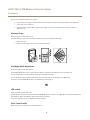
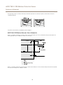
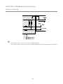
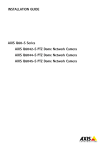
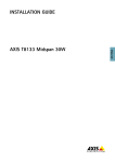
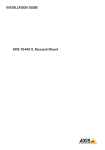
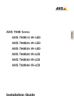
AXIS T8331 PIR Motion Detector Series
User Manual
About this Document
This manual is intended for administrators and users of AXIS T8331 PIR
Motion Detector Series. It includes instructions for using and managing
the product on your network. Later versions of this document will be
posted at www.axis.com
Legal Considerations
Video and audio surveillance can be regulated by laws that vary from
country to country. Check the laws in your local region before using
this product for surveillance purposes.
Liability
Every care has been taken in the preparation of this document. Please
inform your local Axis office of any inaccuracies or omissions. Axis
Communications AB cannot be held responsible for any technical or
typographical errors and reserves the right to make changes to the
product and manuals without prior notice. Axis Communications AB
makes no warranty of any kind with regard to the material contained
within this document, including, but not limited to, the implied
warranties of merchantability and fitness for a particular purpose. Axis
Communications AB shall not be liable nor responsible for incidental or
consequential damages in connection with the furnishing, performance
or use of this material. This product is only to be used for its intended
purpose.
Intellectual Property Rights
Axis AB has intellectual property rights relating to technology embodied
in the product described in this document. In particular, and without
limitation, these intellectual property rights may include one or more
of the patents listed at www.axis.com/patent.htm and one or more
additional patents or pending patent applications in the US and other
countries.
Equipment Modifications
This equipment must be installed and used in strict accordance with the
instructions given in the user documentation. This equipment contains
no user-serviceable components. Unauthorized equipment changes or
modifications will invalidate all applicable regulatory certifications
and approvals.
Trademark Acknowledgments
AXIS COMMUNICATIONS, AXIS, ETRAX, ARTPEC and VAPIX are
registered trademarks or trademark applications of Axis AB in various
jurisdictions. All other company names and products are trademarks or
registered trademarks of their respective companies.
Disposal and Recycling
When this product has reached the end of its useful life, dispose of
it according to local laws and regulations. For information about
your nearest designated collection point, contact your local authority
responsible for waste disposal. In accordance with local legislation,
penalties may be applicable for incorrect disposal of this waste.
Europe
This symbol means that the product shall not be disposed of
together with household or commercial waste. Directive 2012/19/EU
on waste electrical and electronic equipment (WEEE) is applicable in
the European Union member states. To prevent potential harm to
human health and the environment, the product must be disposed
of in an approved and environmentally safe recycling process. For
information about your nearest designated collection point, contact
your local authority responsible for waste disposal. Businesses should
contact the product supplier for information about how to dispose
of this product correctly.
This product complies with the requirements of Directive 2011/65/EU on
the restriction of the use of certain hazardous substances in electrical
and electronic equipment (RoHS).
China
This product complies with the requirements of the legislative
act Administration on the Control of Pollution Caused by Electronic
Information Products (ACPEIP).
Contact Information
Axis Communications AB
Emdalavägen 14
223 69 Lund
Sweden
Tel: +46 46 272 18 00
Fax: +46 46 13 61 30
www.axis.com
Support
Should you require any technical assistance, please contact your Axis
reseller. If your questions cannot be answered immediately, your
reseller will forward your queries through the appropriate channels to
ensure a rapid response. If you are connected to the Internet, you can:
• find answers to resolved problems in the FAQ database. Search
by product, category, or phrase
• report problems to Axis support staff by logging in to your private
support area
• chat with Axis support staff
• visit Axis Support at www.axis.com/techsup/
Learn More!
Visit Axis learning center www.axis.com/academy/ for useful trainings,
webinars, tutorials and guides.
AXIS T8331 PIR Motion Detector Series
Table of Contents
Functions . . . . . . . . . . . . . . . . . . . . . . . . . . . . . . . . . . . . . . . . . . . . . . . . . .
I/O and Event Configuration . . . . . . . . . . . . . . . . . . . . . . . . . . . . . . . . . . . . . . .
Walk Test . . . . . . . . . . . . . . . . . . . . . . . . . . . . . . . . . . . . . . . . . . . . . . . . . . . . . .
Masking Strips . . . . . . . . . . . . . . . . . . . . . . . . . . . . . . . . . . . . . . . . . . . . . . . . . .
Day/Night Mode Adjustment . . . . . . . . . . . . . . . . . . . . . . . . . . . . . . . . . . . . . .
LED switch . . . . . . . . . . . . . . . . . . . . . . . . . . . . . . . . . . . . . . . . . . . . . . . . . . . . .
Pulse Count Switch . . . . . . . . . . . . . . . . . . . . . . . . . . . . . . . . . . . . . . . . . . . . . .
Sensitivity Switch . . . . . . . . . . . . . . . . . . . . . . . . . . . . . . . . . . . . . . . . . . . . . . .
Detection Area Adjustment . . . . . . . . . . . . . . . . . . . . . . . . . . . . . . . . . . . . . . . .
VMD and PIR . . . . . . . . . . . . . . . . . . . . . . . . . . . . . . . . . . . . . . . . . . . . . . . . . . .
Reference Material . . . . . . . . . . . . . . . . . . . . . . . . . . . . . . . . . . . . . . . . . .
Hardware Overview . . . . . . . . . . . . . . . . . . . . . . . . . . . . . . . . . . . . . . . . . . . . . .
AXIS T8331 PIR Motion Detector Series Graphs . . . . . . . . . . . . . . . . . . . . . . .
AXIS T8331 PIR Motion Detector Series Terminal Connections . . . . . . . . . . . .
AXIS T8331 PIR Motion Detector Series Schematics . . . . . . . . . . . . . . . . . . . .
3
4
4
4
5
5
5
5
6
6
6
8
8
9
10
11
AXIS T8331 PIR Motion Detector Series
Functions
Functions
I/O and Event Configuration
Below text applies to both AXIS T8331 and AXIS T8331-E.
This section contains information of I/O configuration and Events on the Camera. For more information and specifications about the
products I/O and Event functionality see the products User Manual available on www.axis.com
I/O Port Configuration
1. Go to Setup – System Options – Ports & Devices – I/O Ports
2. Set port 1 to Input (default)
3. Set Normal state is to Grounded circuit
4. Press Save
Note
• If the port is used in an event, it is not possible to switch between Input and Output until the event is changed or removed.
• It is only possible to manually set Input or Output if the camera provides two or more configurable I/O ports.
Event Configuration
1. Go to the Events setup page and select Action Rules.
2. Select Add.
3. Type in a name for the Action Rule.
4. Select Input Signal from the Trigger drop-down list.
-
Select Digital Input Port from the drop-down list below.
-
Select 1 or 2 from the drop-down list below.
-
Make sure Active: is set to Yes.
5. Select a value from the Schedule drop-down list (Always is selected by default) or manually set a value by select
New schedule.
6. Select an action from the Type drop-down list.
7. Press OK in order to save the Action Rule
The Action Rule will now be in the list of Action Rules.
Walk Test
It is recommended to perform a walk test after installation to confirm that the PIR sensor is working properly.
Before the test, make sure the PIR sensor is configured as below:
•
Set the photocell to DAY (default setting).
•
Set the Pulse count switch to TEST.
•
Set the LED switch to ON (default setting). This applies to AXIS T8331 only.
After the warmup period is completed (approximately 60 s), conduct a walk test by moving in the detection zone of the PIR sensor.
The LED lights when the PIR sensor detects a moving object.
4
AXIS T8331 PIR Motion Detector Series
Functions
After the test, configure the PIR sensor as below:
•
Set the photocell according to the environment, DAY is the default setting and is recommended for most applications.
•
Set the Pulse count switch to 2.
•
Set the LED switch to ON or OFF. See LED switch on page 5 for more information about the LED. This applies to
AXIS T8331 only.
Masking Strips
Below text applies to AXIS T8331–E only.
Unwanted detection zones can be eliminated by masking the lens with provided masking strips.
1. Remove the cover.
2. Apply the masking strip to the zones that should be excluded.
a
e
d
b
e
c d
b a b
d c
e
d
e
f
c
c
c
e
c b a b c d
d
b
a
b
e
c
f
f
d
f
f
e
Day/Night Mode Adjustment
Below text applies to AXIS T8331–E only.
The Day/Night Mode switch can be used to adjust the detector according to the brightness of the surrounding area.
For best performance it is recommended to set the dial to DAY (default setting).
To have the detector begin to function only after it has become dark, turn the dial gradually to the NIGHT side.
For position of the Day/Night Mode switch, see Hardware Overview on page 8
NIGHT
DAY
LED switch
Below text applies to AXIS T8331 only.
For AXIS T8331 it is possible to set the LED switch to OFF/ON. By default the switch is set to ON. When in this mode the LED will lit
when triggered. When set to OFF the LED will not be lit when triggered.
For position of the LED switch, see Hardware Overview on page 8
Pulse Count Switch
Below text applies to both AXIS T8331 and AXIS T8331-E.
5
AXIS T8331 PIR Motion Detector Series
Functions
The Pulse Count switch can be set in two different modes, 2 or TEST. Mode 2 is the default mode and is recommended to use.
TEST is only used when performing a walk test.
For position of the Pulse Count switch, see Hardware Overview on page 8
Sensitivity Switch
The Sensitivity switch can be used to adjust the sensitivity of the detector. There are three different modes.
•
M (Medium) This is the default position and can be used for normal applications.
•
H (High) Use this when the application requires high sensitivity. When using AXIS T8331–E in Pet Alley Area mode, it is
recommended to set the sensitivity mode to H.
•
L (Low) Use this in applications that may be unstable.
For position of the Sensitivity switch, see Hardware Overview on page 8
Detection Area Adjustment
Below text applies to AXIS T8331–E only.
For AXIS T8331–E it is possible to set the detection area. There are two different modes.
•
Multi-Level Area. This is the default mode and is applicable to normal applications.
•
Pet Alley Area. This mode provides a horizontal detection pattern with no declination of zones, allowing pets to move
through the area.
Note
Ideal mounting height for Pet Alley Area is 1.2 m to 1.5 m.
See AXIS T8331 PIR Motion Detector Series Graphs on page 9 for graphs of Multi-Level Area and Pet Alley Area.
See Hardware Overview on page 8 for position of the Detection Area screw and the mirror.
See below for how to switch to Pet Alley Area mode.
1. Carefully loosen the adjustment screw.
2. Slide the cover down and fasten the screw at the P position.
3. Flip the mirror to the upper position.
VMD and PIR
AXIS Video Motion Detection (VMD) is an application for Axis camera products. VMD can be used together with the PIR sensor. The
application detects moving objects within a predefined area of interest, making it possible to automatically trigger an event.
6
AXIS T8331 PIR Motion Detector Series
Functions
Note
The VMD detection area and the PIR sensors detection pattern are not synchronized by default. VMD detection area can be
set in a user interface. The detection pattern for AXIS T8331–E can be modified by using the supplied masking strips.
For more information about AXIS Video Motion Detection, see the products User Manual available on www.axis.com
7
AXIS T8331 PIR Motion Detector Series
Reference Material
Reference Material
Hardware Overview
AXIS T8331
1
2
3
5
4
SENS
LED
LMH
6
OFF ON
7
1
2
3
4
5
6
7
I/O interface
Terminals
PIR sensor (do not touch)
Sensitivity switch
Tamper switch
LED switch
LED
AXIS T8331–E
8
AXIS T8331 PIR Motion Detector Series
Reference Material
7
1
8
2
3
9
4
10
5
11
6
1
2
3
4
5
6
7
8
9
10
11
Day/Night mode adjustment
Mirror
Photocell
LED
Detection area adjustment screw
I/O interface
Pulse count switch
Tamper switch
PIR sensor (do not touch)
Sensitivity switch
Terminals
AXIS T8331 PIR Motion Detector Series Graphs
AXIS T8331 graph
9
AXIS T8331 PIR Motion Detector Series
Reference Material
The large graph above shows a top view of the detection zones.
The small graph above shows a side view of the detection zones when the PIR sensor is mounted on a height of 2.4 m. Ideal mounting
height is between 1.5 m to 2.4 m.
AXIS T8331–E graph
2.5
2
1
2.5
2
1
8.3 ft
5 ft
8.3 ft
5 ft
The large graph above shows a top view of the detection zones.
The small graphs above shows a side view of the detection zones. Multi-level area and Pet alley area.
AXIS T8331 PIR Motion Detector Series Terminal Connections
AXIS T8331
Below are images of the terminal connection for AXIS T8331.
The left image shows the default connection with tamper and alarm together.
The right image shows a connection with tamper and alarm separated. This connection requires a camera with at least two
configurable I/O ports.
AXIS T8331
For position of the terminals, see Hardware Overview on page 8
AXIS T8331–E
Below are images of the terminal connection for AXIS T8331–E.
The left image shows the default connection with tamper and alarm together.
10
AXIS T8331 PIR Motion Detector Series
Reference Material
The right image shows a connection with tamper and alarm separated. This connection requires a camera with at least two
configurable I/O ports.
AXIS T8331-E
For position of the terminals, see Hardware Overview on page 8
AXIS T8331 PIR Motion Detector Series Schematics
Below is a schematic showing the connection with a camera and the PIR sensor. This is the default connection with tamper and
alarm together (Pin 3). Pin 1 GND, Pin 2 Power, Pin 4 not used.
Camera
1
PIR
Supply of PIR
2
PIRAlarm N.C.
Tampering Switch N.C.
3
4
1.
2.
3.
4.
GND
Power
I/O confi gured as input
Not use d
Below is a schematic showing the connection with a camera and the PIR sensor. In this connection tamper and alarm are separated.
Pin 3 alarm, Pin 4 tamper. Pin 1 GND, Pin 2 Power.
11
AXIS T8331 PIR Motion Detector Series
Reference Material
Camera
1
PIR
Supply of PIR
2
PIRAlarm N.C.
3
Tampering Switch N.C.
4
1.
2.
3.
4.
GND
Power
I/O confi gured as input
I/O confi gured as input
Note
• This connection requires a camera with at least two configurable I/O ports.
• This connection requires changes in the terminal, see AXIS T8331 PIR Motion Detector Series Terminal Connections on page 10
12
User Manual
AXIS T8331 PIR Motion Detector Series
© Axis Communications AB, 2015
Ver. M1.13
Date: November 2015
Part No. 1518265