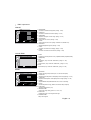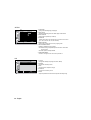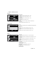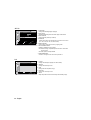
1
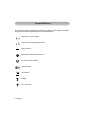
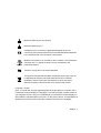
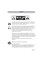
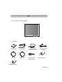
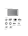
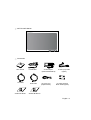
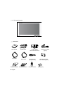
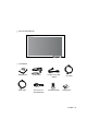
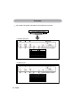
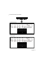
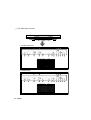
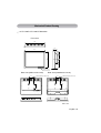
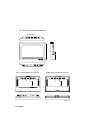
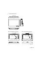
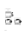
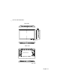
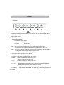
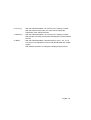
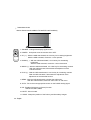
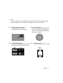
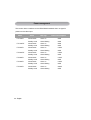
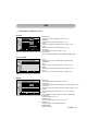
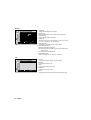
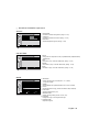
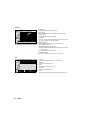
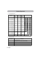
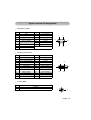
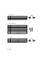
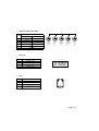
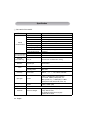
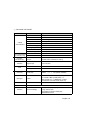
MEDICAL LCD MONIT OR
USER'S GUIDE
Before connecting, operating or adjusting this
product, please read this instruction booklet
carefully and completely.
MEDICAL LCD MONITOR
FS-L190*D (19”)
FS-L190*DT (19”)
FS-L240*D (24”)
FS-L240*DT (24”)
FS-L260*D (26”)
FS-L320*D (32”)
FS-L420*D (42”)
Model definition
F S- L X X X * D T
1
1. FS
2. L
3. XXX
4. *
5. D
6. T
2
3
4
: Monitor manufacturer.
: Panel manufacturer.
: Display size.
: Signal input option.
: Medical grade.
: Touch screen installed.
5
6
Table of Contents
Symbol Definitions ……………………………………………… 2
Safety Instructions ……………………………………………… 4
Caution …………………………………………………………… 7
FCC Information ………………………………………………… 10
Parts ……………………………………………………………… 15
● FS-L190*D / FS-L190*DT …………………………………… 15
● FS-L240*D / FS-L240*DT …………………………………… 16
● FS-L260*D …………………………………………………… 17
● FS-L320*D …………………………………………………… 18
● FS-L420*D …………………………………………………… 19
Connector ……………………………………………………… 20
● FS-L190*D / FS-L240*D / FS-L260*D / FS-L320*D ………… 20
● FS-L190*DT / FS-L240*DT ………………………………… 21
● FS-L420*D …………………………………………………… 22
Mechanical Product Drawing …………………………………… 23
● 19” FS-L190*D / FS-L190*DT ……………………………… 23
● 24” FS-L240*D / FS-L240*DT ……………………………… 24
● 26” FS-L260*D ……………………………………………… 25
● 32” FS-L320*D ……………………………………………… 26
● 42” FS-L420*D ……………………………………………… 27
Control …………………………………………………………… 28
Power management …………………………………………… 32
OSD ……………………………………………………………… 33
Standard Signal table …………………………………………… 48
Signal connector Pin Assignments ……………………………… 49
Specification ……………………………………………………… 52
● FS-L190*D / FS-L190*DT …………………………………… 52
● FS-L240*D / FS-L240*DT …………………………………… 53
● FS-L260*D ……………………………………………………54
● FS-L320*D …………………………………………………… 55
● FS-L420*D …………………………………………………… 56
English - 1
Symbol Definitions
The following symbols appear on the product, its labels, or the product package.
Each symbol carries a special definition, as defined below.
Dangerous : High Voltage.
Consult accompanying documents.
Direct Current.
lndicates protective earth ground.
DC Power control switch.
Serial Number.
Top-Bottom.
Fragile.
Do not get wet.
2 - English
Maximum Stacking.(19”/24”/26”/32”)
Maximum Stacking.(42”)
Indicates proof of conformity to applicable European Economic
Community Council directives and to harmonized standards published
in the official journal of the European Communities.
Medical LCD monitor is in accordance with UL 60601-1 and CAN/CSA
C22.2 No.601.1 in regards to electric shock, fire hazards, and
mechanical hazard.
Tested to comply with FCC Class B standard.
This symbol indicates that the waste of medical LCD monitor must not
be disposed as unsorted municipal waste and must be collected
separately. Please contact the manufacturer or other authorized
disposal company to decommission your medical LCD monitor.
Language : English
Note : A manual with a proper legal language will be provided for a member of EU.
Foreseeson Custom Display Inc.language. If you find an English version instead of
your language version, call your local distributor or Foreseeson Custom Display Inc.
will include the manual written in the local . for the proper version. This declaration is
applied to the member of EU where this medical LCD monitor is sold legally.
English - 3
Safety Instructions
On Safety
1. Before connecting the AC power cord to the DC adapter outlet make sure the
voltage designation of the DC adapter corresponds to the local electrical
supply.
2. Never insert anything metallic into the cabinet openings of the medical LCD
monitor. Doing so may create the danger of electric shock.
3. To reduce the risk of electric shock, do not remove cover.
No user-serviceable parts inside. Only a qualified technician should open the
case of the medical LCD monitor.
4. Never use your medical LCD monitor if the power cord has been damaged.
Do not allow anything to rest on the power cord, and keep the cord away from
areas where people can trip over it.
5. Be sure to hold the plug, not the cord,when disconnecting the medical LCD monitor
power cord from an electric socket.
6. Unplug your medical LCD monitor power cord when it is going to be left unused
for an extended period of time.
7. Unplug your medical LCD monitor power cord from the AC outlet before any service.
8. If your medical LCD monitor does not operate normally, in particular, if there are
any unusual sounds or smells coming from it, unplug it immediately and contact
an authorized dealer or service center.
9. Please contact the manufacturer if the set should be installed in an inaccessible
area.
Warning
Do not touch input or output connectors and the patient simultaneously.
4 - English
Warning
This medical LCD monitor is intended for connection to input/output signals and other
connectors that comply with relevant IEC standard (e.g.,IEC60950 for IT
equipment and IEC60601 series for medical electrical equipment).
In addition, all such combination-system shall comply with the standard IEC
60601-1-1, safety requirements for medical electrical systems. Any person who
has formed a combination-system is responsible for the system to comply with the
requirements of IEC 60601-1-1.
If in doubt, contact qualified technician or your local representative.
On installation
1. Openings in the medical LCD monitor cabinet are provided for ventilation.
To prevent overheating, these openings should not be blocked or covered. If
you put the medical LCD monitor in a bookcase or some other enclosed
space, be sure to provide adequate ventilation.
2. Put your medical LCD monitor in a location with low humidity and a minimum
of dust.
3. Do not expose the medical LCD monitor to rain or use it near water
(in kitchens, near swimming pools, etc.). If the medical LCD monitor
accidentally gets wet, unplug it and contact an authorized dealer immediately.
You can clean the medical LCD monitor with a damp cloth if necessary,
but be sure to unplug the medical LCD monitor first.
4. Place your medical LCD monitor near an easily accessible AC outlet.
5. High temperature can cause problems. Don't use your medical LCD monitor in
direct sunlight and keep it away from heaters, stoves, fireplaces,and sources
of heat.
6. Don’t place your medical LCD Monitor on an unstable stand, Medical LCD monitor
may malfunction or fall.
7. This medical LCD monitor should not topple over when tilted at a 5° angle, in any
position, during NORMAL USE, excluding transport.
8. In the position specified for transport, medical LCD monitor shall not overbalance
when tilted at a 10 degree angle.
English - 5
Environmental Conditions for operation and Storage
- Temperature range within 0°C to 40°C(operation), -20°C to 60°C(storage)
- Relative humidity range 10% to 85%
Atmospheric pressure range within 500 to 1060hPa.
Intended Use
- This Medical LCD Monitor is an accessory intended for use with Medical Equipment
to display alphabetical, numerical and graphical data.
6 - English
CAUTION
This symbol alerts the user that important literature concerning the
operation of this unit has been included. Therefore, it should be read
carefully in order to avoid potential problems.
This symbol warns user that un-insulated voltage within the unit may
have sufficient magnitude to cause electrical shock. Therefore, it is
dangerous to make contact with any part inside the unit. To reduce
the risk of electric shock, DO NOT remove cover (or back).
There are no user serviceable parts inside. Refer servicing to
qualified service personnel.
To prevent fire or shock hazards, do not expose this unit to rain or
moisture. Also, do not use this unit's polarized plug with an extension
cord receptacle or other outlets unless the prongs can be fully inserted.
The display is designed to meet the medical safety requirements for a
patient vicinity device.
This device may not be used in connection with life support
equipment.
Underwriters Laboratories (UL) Classification:
UL safety Compliance:
This medical LCD monitor is U.L. Classified WITH RESPECT TO
ELECTRIC SHOCK, FIRE AND MECHANICAL HAZARDS ONLY IN
ACCORDANCE WITH UL 60601-1/CAN/CSA C22.2 NO. 601.1
English - 7
EEC Safety Compliance
This medical LCD monitor unit meets the requirements of EN-60601-1
so as to conform to the Medical Device Directive 93/42/EEC
(general safety information).
Use 120V rating 5-15P type plug only in the U.S
This medical LCD monitor complies to the above standards only when used with the
supplied medical grade power supply.
19”(FS-L190*D / FS-L190*DT)
JMW190KA1200F02(BRIDGE POWER CORP.)
24”/26”(FS-L240*D / FS-L240*DT / FS-L260*D)
JMW1150KA2400F04(BRIDGE POWER CORP.)
32”(FS-L320*D) JMW1180KA2400F01(BRIDGE POWER CORP.)
Caution: Make sure the power cord is the correct type that is required in your area.
This medical LCD monitor has a universal power supply that allows operation in
either 100-120V AC or 200-240V AC voltage areas (no user adjustment is required).
Use the proper power cord with correct attachment plug type. If the power source is
120 V AC, use a power cord which is a Hospital Grade Power Cord with NEMA 5-15
style plug, labeled for 125 volts AC with UL and C-UL approvals. If the power source
is a 240 V AC supply, use the tandem (T blade) type attachment plug with ground
conductor power cord that meets the respective European country's safety
regulations.
The hospital-grade plug for medical products intended for use in Denmark has
DEMKO approval and is rated 13 amps at 250Vac. Plug is recommended for use in
medical applications and specifications are being added to the standard SB
107-2-D1. Plug mates with maker's Danish hospital-grade socket. Hospital sockets
have slightly different shaped openings allowing only the hospital plug, not the
standard Danish plug, to be inserted, to protect the ac circuit in specific medical
settings.
Recycling
Follow local governing ordinances and recycling plans regarding the
recycling or disposal of this equipment.
8 - English
Cleaning Instructions
Follow your hospital protocol for the handling of blood and body
fluids. Clean the display with a diluted mixture of mild detergent and
water. Use a soft towel or swab.
Use of certain detergents may cause degradation to the labels
and plastic components of the product.
Consult cleanser manufacturer to see if agent is compatible.
Do not allow liquid to enter the display.
Servicing
Do not attempt to service the medical LCD monitor yourself, as opening or
removing covers may expose you to dangerous voltages or other hazards, and
will void the warranty. Refer all servicing to qualified service personnel.
Unplug the medical LCD monitor from its power source and refer servicing to
qualified personnel under the following conditions:
- If the power cord or plug is damaged or frayed.
- If liquid has been spilled into the medical LCD monitor.
- If objects have fallen into the medical LCD monitor.
- If the medical LCD monitor has been exposed to rain or moisture.
- If the medical LCD monitor has been subjected to excessive shock by being
dropped.
- If the cabinet has been damaged.
- If the medical LCD monitor seems to be overheated.
- If the medical LCD monitor emits smoke or abnormal odor.
- If the medical LCD monitor fails to operate in accordance with the operating
instructions.
Accessories
Use only accessories specified by the manufacturer, or sold with the medical
LCD monitor.
Classification
- Protection against electric shock : Class I including AC/DC Adapter
- Applied Parts : No Applied Parts
- Degree of safety in the presence of flammable anesthetics mixture with air or
with oxygen or with nitrous oxide.
Not suitable for use in the presence of a flammable anesthetics mixture with
oxygen or with nitrous oxide.
- Mode of operation : Continuous.
English - 9
FCC Information
This medical LCD monitor unit has been tested and found to comply with the
limits of a Class B digital device, pursuant to Part 15 of the FCC rules.
These limits are designed to provide reasonable protection against interference.
This monitor can radiate radio frequency energy and, if not installed and used in
accordance with the instructions, it may interfere with other radio communications
equipment. There is no guarantee that interference will not occur in a particular
installation.
If this equipment is found to cause harmful interference to radio or television
reception, the user is encouraged to try to correct the interference by carrying out
one or more of the following measures:
1. Reorient or relocate the receiving antenna.
2. Increase the distance between the medical LCD monitor and the subject of
interference.
3. Plug the monitor into an outlet on a different electrical circuit than that to which
the subject of interference is connected.
4. Consult the dealer or an experienced radio/TV technician for help.
NOTICES TO USER
This device complies with part 15 of the FCC Rules. Operation is subject to the
following two conditions:
(1) this device may not cause harmful interference, and (2) this device must
accept any interference received, including interference that may cause
undesired operation.
FCC WARNING
This medical LCD monitor generates or uses radio frequency energy. Changes
or modifications to this medical LCD monitor may cause harmful interference
unless the modifications are expressly approved in the instruction manual. The
user could lose authority to operate this equipment if an unauthorized change or
modification is made.
10 - English
1. Guidance and manufacturer's declaration - electromagnetic emissions
The medical LCD monitor is intended for use in the electromagnetic environment specified below.
The customer or the user of the medical LCD monitor should assure that it is used in such an environment.
Emission test
RF Emissions
CISPR 11
Group 1
RF Emissions
CISPR 11
Class B
Harmonic emissions
IEC 61000-3-2
Electromagnetic environment -guidance
Compliance
D
The medical LCD monitor uses RF energy only for its internal
function. Therefore, its RF emissions are very low and are not
likely to cause any interference in nearby electronic equipment
The medical LCD monitor is suitable for use in all establishments,
including domestic establishments and those directly connected
to the public low-voltage power supply network that supplies
buildings used for domestic purposes
Voltage fluctuations
Complies
IEC 61000-3-3
2. Guidance and manufacturer's declaration - electromagnetic immunity
This medical LCD monitor is intended for use in the electromagnetic environment specified below.
The customer or the user of the medical LCD monitor should assure that it is used in such an environment.
Immunity test
IEC 60601 Test level
Compliance level
Electrostatic
6kV Contact
6kV Contact
discharge(ESD)
8kV air
8kV air
IEC61000-4-2
Electrical fast
transient/burst
IEC 61000-4-4
Electromagnetic environment -guidance
Floors should be wood,concrete or
ceramic tile. If floors are covered with
synthetic material, the relative humidity
should be at least 30%
2kV for power supply 2kV for power supply Mains power quality should be that of a
lines
lines
typical commercial or hospital environment.
1kV for input/output
1kV for input/output
lines
lines
English - 11
Surge
1kV differential mode
IEC 61000-4-5
2kV common mode
1kV differential mode Mains power quality should be that of a
2kV common mode
typical commercial or hospital environment.
Conducted RF
3 Vrms
3 Vrms
IEC 61000-4-6
150 kHz to 80MHz
150 kHz to 80MHz
Portable and mobile RF communications
equipment should be used no closer to any
part of the medical LCD monitor, including
cables, than the recommended separation
distance calculated from the equation
applicable to the frequency of the transmitter.
Recommended separation distance : d
where P is the maximum output power rating
of the transmitter in watts (W)
3. Guidance and manufacturer's declaration - electromagnetic immunity
This medical LCD monitor is intended for use in the electromagnetic environment specified below.
The customer or the user of monitor should assure that it is used in such an environment.
Immunity test
Power frequency
(50/60Hz)
magnetic field
IEC 61000-4-8
Voltage dips,
short interruptions
and voltage
variations on
power supply
input lines
IEC 61000-4-11
12 - English
IEC 60601 Test level
Compliance level
3.0A/m
3.0A/m
<5 % U T
(>95 % dip in U T )
for 0.5 cycle
40 % U T
(60 % dip in U T )
for 5 cycle
70 % U T
(30 % dip in U T )
for 25 cycle
<5 % U T
(<95 % dip in U T )
for 5 sec.
<5 % U T
(>95 % dip in U T )
for 0.5 cycle
40 % U T
(60 % dip in U T )
for 5 cycle
70 % U T
(30 % dip in U T )
for 25 cycle
<5 % U T
(<95 % dip in U T )
for 5 sec.
Electromagnetic environment -guidance
Power frequency magnetic fields should be
at levels characteristic of a typical location
in a typical commercial or hospital
environment.
Main power quality should be that of a typical
commercial or hospital environment. If the
user of monitor requires continued operation
during power mains interruptions, it is
recommended that monitor be powered
from an uninterruptible power supply or a
battery.
NOTE : U¨T the A.C. mains voltage prior to
application of the test level.
Immunity test
IEC 60601 Test level
Electromagnetic environment -guidance
Compliance level
Recommended separation distance
80MHz to 800MHz
80MHz to 2.5GHz
Radiated RF
IEC 61000-4-3
3 V/m
3 V/m
80.0 MHz to 2.5 GHz 80.0 MHz to 2.5 GHz where P is the maximum output power rating
of the transmitter in watts (W) according to
the transmitter manufacturer and d is the
recommended separation distance in meters
(m).
Field strengths from fixed RF transmitters, as
determined by an electromagnetic site
survey, It should be less than the compliance
level in each frequency range.
4. Recommended separation distances between portable and mobile RF
communications equipment and this medical LCD monitor.
- The medical LCD monitor is intended for use in an electromagnetic environment in
which radiated RF disturbances are controlled.
The customer or the user of the monitor can help prevent electromagnetic interference
by maintaining a minimum distance between portable and mobile RF communications
equipment (transmitters) and the medical LCD monitor as recommended below,
according to the maximum output power of the communications equipment.
Separation distance according to frequency of transmitter[m]
Rated maximum
output power of
transmitter [W]
150kHz to 80MHz
80MHz to 800MHz
800MHz to 2.5GHz
V1=3Vrms
E1=3V/m
E1=3V/m
English - 13
0.01
0.116
0.116
0.2333
0.1
0.368
0.3687
0.7378
1
1.166
1.1660
0.2333
10
3.687
3.6872
0.7375
100
11.660
11.6600
23.333
For transmitters rated at a maximum output power not listed above, the recommended separation distance d
in meters (m)can be estimated using the equation applicable to the frequency of the transmitter, where p is
the maximum output power rating of the transmitter in watts (W) according to the transmitter manufacturer.
NOTE 1) At 80MHz and 800MHz, the separation distance for the higher frequency range applies.
NOTE 2) These guidelines may not apply in all situations. Electromagnetic propagation is affected by
absorption and reflection from structures, objects and people.
14 - English
Parts
19" FS-L190*D / FS-L190*DT Monitor
Accessories
User Manual
DVI Cable
D-SUB Cable
BNC Cable
AC-DC Adaptor
(JMW190KA1200F02)
AC Power cord
(Hospital Grade)
S-Video (Y/C) Cable
(Option)
SCREW FH M3X6
SCREW BH M4X10
English - 15
24" FS-L240*D / FS-L240*DT Monitor
Accessories
User Manual
DVI Cable
SCREW FH M3X6
16 - English
D-SUB Cable
BNC Cable
SCREW BH M4X10
AC-DC Adaptor
(JMW1150KA2400F04)
AC Power cord
(Hospital Grade)
S-Video (Y/C) Cable
(Option)
DC Cable Terminal
Male / female (Option)
26" FS-L260*D Monitor
Accessories
User Manual
DVI Cable
SCREW FH M3X6
D-SUB Cable
BNC Cable
AC-DC Adaptor
(JMW1150KA2400F04)
AC Power cord
(Hospital Grade)
S-Video (Y/C) Cable
(Option)
DC Cable Terminal
Male / female (Option)
SCREW BH M4X10
English - 17
32" FS-L320*D Monitor
Accessories
User Manual
DVI Cable
D-SUB Cable
BNC Cable
SCREW FH M3X6 SCREW BH M4X10
18- English
AC-DC Adaptor
(JMW1180KA2400F01)
AC Power cord
(Hospital Grade)
Remote controller
S-Video (Y/C) Cable
(Option)
DC Cable Terminal
Male / female (Option)
Battery(AAA)
42" FS-L420*D Monitor
Accessories
User Manual
BNC Cable
D-SUB Cable
AC Power cord
(Hospital Grade)
S-Video (Y/C) Cable
(Option)
Remote controller
DVI Cable
Battery(AAA)
English - 19
Connector
FS-L190*D / FS-L240*D / FS-L260*D / FS-L320*D Input connector
▶ DVI fiber optic input
DC Input
SDI OUT
DC ON/OFF SWITCH
S-VIDEO /Y
OPTICAL IN
S-VIDEO /C
DVI IN
C-VIDEO
DVI OUT
RED /Pr
VGA IN
GREEN /Y
GPIO
BLUE /Pb
RS232C
C-SYNC/H-SYNC
SDI IN
V-SYNC
▶ Dual DVI input
20 - English
DC Input
SDI OUT
DC ON/OFF SWITCH
S-VIDEO /Y
DVI 2 IN
S-VIDEO /C
DVI 1 IN
C-VIDEO
DVI 1 OUT
RED /Pr
VGA IN
GREEN /Y
GPIO
BLUE /Pb
RS232C
C-SYNC/H-SYNC
SDI IN
V-SYNC
FS-L190*DT / FS-L240*DT input connector
▶ DVI fiber optic input
DC Input
SDI IN
DC ON/OFF SWITCH
SDI OUT
OPTICAL IN
S-VIDEO /Y
DVI IN
S-VIDEO /C
DVI OUT
C-VIDEO
VGA IN
RED /Pr
GPIO
GREEN /Y
USB TOUCH
BLUE /Pb
SERIAL TOUCH
C-SYNC/H-SYNC
RS232C
V-SYNC
DC Input
SDI IN
DC ON/OFF SWITCH
SDI OUT
DVI 2 IN
S-VIDEO /Y
DVI 1 IN
S-VIDEO /C
DVI 1 OUT
C-VIDEO
VGA IN
RED /Pr
GPIO
GREEN /Y
USB TOUCH
BLUE /Pb
SERIAL TOUCH
C-SYNC/H-SYNC
RS232C
V-SYNC
▶ Dual DVI input
English - 21
FS-L420*D Input connector
▶ DVI fiber optic input
AC ON/OFF SWITCH
SDI OUT
AC Inlet
S-VIDEO /Y
OPTICAL IN
S-VIDEO /C
DVI IN
C-VIDEO
DVI OUT
RED /Pr
VGA IN
GREEN /Y
GPIO
BLUE /Pb
RS232C
C-SYNC /H-SYNC
SDI IN
V-SYNC
AC ON/OFF SWITCH
SDI OUT
AC Inlet
S-VIDEO /Y
DVI 2 IN
S-VIDEO /C
DVI 1 IN
C-VIDEO
DVI 1 OUT
RED /Pr
VGA IN
GREEN /Y
GPIO
BLUE /Pb
RS232C
C-SYNC /H-SYNC
SDI IN
V-SYNC
▶ Dual DVI input
22 - English
Mechanical Product Drawing
19” FS-L190*D / FS-L190*DT Dimension
Front view
395
76.5
88.5
89
351.5
114
60
423
31
OSD MEMBRANE SWITCH
Rear view (Installed I/O Cover)
4-M4X12(VESA MOUNT HOLE)
100
100
4-M4X12(VESA MOUNT HOLE)
100
100
Rear view (Without I/O Cover)
Unit : mm
English - 23
24” FS-L240*D / FS-L240*DT Dimension
Front view
95
580
44
124.3
68.7
386
51
OSD MEMBRANE SWITCH
4-M4X12(VESA MOUNT HOLE)
100
100
Rear view (Installed I/O Cover)
4-M4X12(VESA MOUNT HOLE)
100
100
Rear view (Without I/O Cover)
Unit : mm
24 - English
26” FS-L260*D Dimension
Front view
99.5
618
44
107
99
412
55.5
OSD MEMBRANE SWITCH
Rear view (Installed I/O Cover)
4-M4X12(VESA MOUNT HOLE)
4-M4X12(VESA MOUNT HOLE)
200
100
100
200
100
100
Rear view (Without I/O Cover)
Unit : mm
English - 25
32” FS-L320*D Dimension
Front view
100
56 44
242.5
485
795
OSD MEMBRANE SWITCH
400
300
100
4-M6(VESA MOUNT HOLE)
100
200
4-M4X12(VESA MOUNT HOLE)
Rear view (Installed I/O Cover)
4-M4X12(VESA MOUNT HOLE)
400
300
100
4-M6(VESA MOUNT HOLE)
100
200
Rear view (Without I/O Cover)
Unit : mm
26 - English
42” FS-L420*D Dimension
Front view
111.1
55 50
495.4
1221.1
617.4
70.3
1024.6
OSD MEMBRANE SWITCH
Rear view
600
300
200
10-M8(USER MOUNT HOLE)
Unit : mm
English - 27
Control
OSD Button
An 8 button keypad, located in bottom right corner on the front of the display, allows
the user to make adjustments to various display parameters using the On Screen
Display (OSD) system.
● Power Indicating LED
Normal mode (ON): Green
Standby mode
: Blinking Green
Off mode
: Monitor Off
Note 1 : LED normal and off mode sign can be changed according to the
requirement of the customer whether normal mode green is on or off
Note 2 : The main AC power switch, on the back panel, should be in the ON position.
The DC power button is used to turn on the monitor
● On-Screen Display (OSD) Function Button
1. POWER : Soft power turns the monitor ON or OFF
2. MENU : Used to activate to the OSD menu and
exit from main menu or sub menu.
3. PIP
: Enables PIP(picture in Picture) function.
Selects PIP,PBP1,PBP2.
4. UP (▲) : With the OSD deactivated, it is a Hot Key for increasing brightness.
With the OSD activated, moves the cursor upward.
5. DOWN (▼) : With theOSD deactivated, it is a Hot Key for decreasing brightness.
With the OSD activated, moves the cursor downward.
28- English
6. PLUS (+)
7. MINUS (-)
8. INPUT
: With the OSD deactivated, it is a Hot key for increasing contrast.
With the OSD activated, enter sub menu and increases the
adjustment of the selected function.
: With the OSD deactivated, it is a Hot key for increasing contrast.
With theOSD activated, it decreases the adjustment of the selected
function.
: With the OSD deactivated, if pressed down for over 1 sec., it is a
Hot Key for auto-adjustment control under DSUB ANALOG / RGBs
signals.
With theOSD activated, it changes the displayed signal source.
English - 29
Remote button function
<Notice> Remote control is available in FS-L320*D,FS-L420*D models only.
1. SOURCE : Changes the display signal source.
2. POWER : Soft power turns the monitor ON or OFF.
3. UP (▲) : With the OSD deactivated,it is a Hot key for increasing brightness.
With the OSD activated, moves the cursor upward.
4. DOWN (▼) : With the OSD deactivated, it is a Hot key for decreasing
brightness.
With the OSD activated, moves the cursor downward.
5. MINUS (-) : With the OSD deactivated, it is a Hot key for decreasing contrast.
With the OSD activated, it decreases the adjustment of the
selected function.
6. PLUS (+) : With the OSD deactivated, it is a Hot key for increasing contrast.
With the OSD activated, it decreases the adjustment of the
adjustment of the Selected function.
7. MENU : With the OSD deactivated, activates the OSD menu.
With the OSD activated, exits from main menu or sub menu.
8. AUTO : Fits to the most appropriate screen on the D-SUB Analog signal.
9. PIP : Enables PIP(picture in Picture) function.
Selects PIP,PBP1,PBP2
10. MUTE : Sound muted.
11. SWAP : Swaps the position of the Primary and Secondary images.
30 - English
GPIO
There are four pins on the RJ69 GPIO connector. Each pin has a preprogrammed
function assigned to it. The function is initiated when the pin is grounded.
Pin 1. Primary and Secondary Swap.
Grounding this pin will swap
the primary and secondary image.
Pin 3. Record Indicator
The record indicator is displayed in the
top left corner when the pin is ground
to pin 4. The indicator will vanish when
the contact is opened.
Pin 2. PIP,PBP1,PBP2 Single
Pin 4. Connector Ground
Continuously grounding this pin causes
This is the common ground location.
the position and size choices to cycle.
Monitor
RJ69
English - 31
Power management
This monitor does not adhere to the VESA DPMS standard when no signal is
present on the video input.
Model
Status
LED sign
FS-L190*D
Normal mode
Green on
<60W
Standby mode
Green blinking
<20W
Normal mode
Green on
<60W
Standby mode
Green blinking
<20W
Normal mode
Green on
<100W
Standby mode
Green blinking
<20W
Normal mode
Green on
<100W
Standby mode
Green blinking
<20W
Normal mode
Green on
<130W
Standby mode
Green blinking
<20W
Normal mode
Green on
<150W
Standby mode
Green blinking
<20W
Normal mode
Green on
<260W
Standby mode
Green blinking
<20W
FS-L190*DT
FS-L240*D
FS-L240*DT
FS-L260*D
FS-L320*D
FS-L420*D
32 - English
Power Consumption
OSD
DSUB ANALOG / RGBS input source
ADJUST
ADJUST
BRIGHTNESS
50
CONTRAST
50
CLOCK
50
PHASE
65
BACK LIGHT
100
AUTO ADJUST
EXIT
SELECT
MOVE
1280X1024/80K x75Hz
DSUB ANALOG
1. BRIGHTNESS
Increases or decreases the brightness. (Range : 0~100)
2. CONTRAST
Increases or decreases the contrast. (Range : 0~100)
3. CLOCK
Increases or decreases the sampling frequency. (Range : 0~100)
4. PHASE
Increases or decreases the Phase level. (Range : 0~100)
5. BACKLIGHT
Adjusts backlight dimming level. (Range : 0~100)
6. AUTO ADJUST
Fits to the most appropriate screen on the D-SUB Analog / RGBs signal.
COLOR TEMP
COLOR TEMP
MODE
C1
SELECT
EXIT
DSUB ANALOG
MOVE
1280X1024/80K x75Hz
1. MODE
Changes the color mode (C1(Reddish,6500K), C2(Bluish,9300K),
USER(7200K)
2. RED
Red balance.(Only works with USER Mode) (Range : 0~100)
3. GREEN
Green balance.(Only works with USER Mode) (Range : 0~100)
4. BLUE
Blue balance.(Only works with USER Mode) (Range : 0~100)
IMAGE
IMAGE
IMAGE SIZE
FILL
H POSITION
50
V POSITION
50
2.0
GRMMA
FILTER
NORMAL
OVER SCAN
0 1 2 3 4 5 6 7 8
MODE 1
IMAGE SETTING
EXIT
DSUB ANALOG
SELECT
MOVE
1280X1024/80K x75Hz
1. IMAGE SIZE
Changes the image size. (Full,Fill aspect,1:1,Normal)
2. H POSITION
Adjusts the horizontal position of the displayed source image.(Range : 0~100)
3. V POSITION
Adjusts the vertical position of the displayed source image. (Range : 0~100)
4. GAMMA
Adjusts GAMMA value (VIDEO,BYPASS,1.8,2.0,2.2,2.4,2.6,PACS)
5. FILTER
Sets the sharpness of image ( Softest, Soft, Normal, Sharp, Sharpest)
6. OVER SCAN
Adjusts the displayed size. (0~8)
7. IMAGE SETTING
Changes the image setting.(Preset 1,2 / User 1,2,3)
8. ZOOM / PAN
Enlarges the image, moves images left and right.
9. FREEZE FRAME
Keeps the image still.
English - 33
SETUP
SETUP
LANGUAGE
ENGLISH
OSD COLOR
50
OSD POSITION
120 SEC
DURATION
RESET SETTINGS
AUTO SOURCE SELECT ON
USER NAME ENTRY
SELECT
EXIT
MOVE
1280X1024/80K x75Hz
DSUB ANALOG
1. LANGUAGE
Changes the OSD language (8 language)
2. OSD COLOR
Adjusts the OSD background from white opaque to translucent.
3 .OSD POSITION
Changes the osd position. (9 Positions)
4. DURATION
Adjusts the length of time the OSD menu is present on the screen.
(5, 10, 20, 30, 60, 90, 120, 180, 240 seconds)
5. RESET SETTING
Changes all the OSD values make to factory default.
6. AUTO SOURCE SELECT
Disables or enable auto source select.
ON: Searches through all possible input source untill an active video
source is found.
OFF: Video input is manually selected.
7. USER NAME ENTRY
Creates or changes the user name when powered on.
PIP
PIP
LAYOUT
EXIT
DSUB ANALOG
34 - English
SINGLE
SELECT
MOVE
1280X1024/80K x75Hz
1. LAYOUT
Changes the OSD layout. (Single, PIP, PBP1, PBP2)
2. SOURCE
Changes the secondary source.
3. SIZE
Changes the PIP size(Small, Large).
4. POSITION
Changes the secondary source.
5. SWAP
Swaps the position and size of the Primary and Secondary image.
DVI OPTICAL / DVI DIGITAL input source
ADJUST
ADJUST
BRIGHTNESS
50
CONTRAST
50
BACK LIGHT
100
SELECT
EXIT
1. BRIGHTNESS
Increases or decrease the brightness. (Range : 0~100)
2. CONTRAST
Increases or decreases the Contrast. (Range : 0~100)
3. BACKLIGHT
Adjusts backlight dimming level. (Range : 0~100)
MOVE
1280X1024/80K x75Hz
DVI DIGITAL
COLOR TEMP
COLOR TEMP
MODE
C1
SELECT
EXIT
MOVE
DVI DIGITAL
1280X1024/80K x75Hz
1. MODE
Changes the color temperature mode. (C1(Reddish,6500K), C2(Bluish,9300K),
USER(7200K)
2. RED
Red balance. (Only works with USER Mode) (Range : 0~100)
3. GREEN
Green balance. (Only works with USER Mode) (Range : 0~100)
4. BLUE
Blue balance. (Only works with USER Mode) (Range : 0~100)
IMAGE
IMAGE
IMAGE SIZE
FILL
GRMMA
2.0
FILTER
NORMAL
OVER SCAN
0 1 2 3 4 5 6 7 8
IMAGE SETTING
PRESET1
ZOOM/PAN
ON
FREEZE FRAME
EXIT
DVI DIGITAL
SELECT
MOVE
1280X1024/80K x75Hz
1. IMAGE SIZE
Changes the image size. (Full, Fill aspect**, 1:1**, Norma)
**Only in DVI Optical
2. GAMMA
Adjusts GAMMA value. (VIDEO,BYPASS,1.8,2.0,2.2,2.4,2.6,PACS)
3. FILTER
Sets the sharpness of image. ( Softest, Soft, Normal, Sharp, Sharpest)
4. OVER SCAN
Adjusts the displayed size. (0~8)
5. IMAGE SETTING
Changes the image setting. (Preset 1,2 / User 1,2,3)
6. ZOOM/PAN
Enlarges the image, moves images left and right.
7. FREEZE FRAME
Keeps the image still.
English - 35
SETUP
SETUP
LANGUAGE
ENGLISH
OSD COLOR
50
OSD POSITION
120 SEC
DURATION
RESET SETTINGS
AUTO SOURCE SELECT ON
USER NAME ENTRY
EXIT
MOVE
SELECT
1280X1024/80K x75Hz
DVI DIGITAL
1. LANGUAGE
Changes the OSD language (8 language)
2. OSD COLOR
Adjusts the OSD background from white opaque to translucent.
3 .OSD POSITION
Changes the OSD position. (9 Positions)
4. DURATION
Adjusts the length of time the OSD menu is present on the screen.
(5, 10, 20, 30, 60, 90, 120, 180, 240 seconds)
5. RESET SETTING
Changes all the OSD values to factory outgoing state.
6. AUTO SOURCE SELECT
Disables or enables auto source select.
ON: Searches through all possible input source until an active video
source is found.
OFF: Video input is manually selected.
7. USER NAME ENTRY
Creates or changes the user name when powered on.
PIP
PIP
LAYOUT
EXIT
DSUB ANALOG
36 - English
SINGLE
SELECT
MOVE
1280X1024/80K x75Hz
1. LAYOUT
Changes the OSD layout. (Single, PIP, PBP1, PBP2)
2. SOURCE
Changes the secondary source.
3. SIZE
Changes the PIP size(Small, Large).
4. POSITION
Changes the secondary source.
5. SWAP
Swaps the position and size of the Primary and Secondary image.
YPbPr input source
ADJUST
ADJUST
BRIGHTNESS
50
CONTRAST
50
SHARPNESS
50
SATURATION
65
COLOR
0
BACKLIGHT
100
65
PHASE
SELECT
EXIT
MOVE
1920X1080/80K x60Hz
YPbPr
1. BRIGHTNESS
Increases or decreases the brightness. (Range : 0~100)
2. CONTRAST
Increases or decreases the Contrast. (Range : 0~100)
3. SHARPNESS
Adjusts the sharpness of video image. (Range : 0~100)
4. SATURATION
Changes the tone of color. (Range : 0~100)
5. COLOR
Changes the richness of color. (Range : Greenish 0~50, Redish 0~50)
6. BACKLIGHT
Adjusts backlight dimming level. (Range : 0~100)
7. CLOCK
Increases or decreases the sampling. (Range : 0~100)
8. PHASE
Increases or decreases the Phase level. (Range : 0~100)
COLOR TEMP
COLOR TEMP
MODE
EXIT
C1
MOVE
SELECT
YPbPr
1920X1080/80K x60Hz
1. MODE
Changes the color temperature mode. (C1(Reddish,6500K), C2(Bluish,9300K),
USER(7200K)
2. RED
Red balance. (Only works with USER Mode) (Range : 0~100)
3. GREEN
Green balance. (Only works with USER Mode) (Range : 0~100)
4. BLUE
Blue balance.(Only works with USER Mode) (Range : 0~100)
IMAGE
IMAGE
IMAGE SIZE
FILL
V POSITON
50
H POSITON
50
GRMMA
2.0
FILTER
NORMAL
OVER SCAN
0 1 2 3 4 5 6 7 8
IMAGE SETTING
EXIT
YPbPr
SELECT
PRESET1
MOVE
1920X1080/80K x60Hz
1. IMAGE SIZE
Changes the image size.(Full, Fill aspect, 1:1, Normal, Anamorphic)
2. H POSITION
Adjusts the horizontal position of the displayed source image.(Range : 0~100)
3. V POSITION
Adjusts the vertical position of the displayed source image. (Range : 0~100)
4. GAMMA
Adjusts GAMMA value.(VIDEO,BYPASS,1.8,2.0,2.2,2.4,2.6,PACS))
5. FILTER
Sets the sharpness of image.( Softest, Soft, Normal, Sharp, Sharpest)
6. OVER SCAN
Adjusts the displayed size. (0~8)
7. IMAGE SETTING
Changes the image setting.(Preset 1,2 / User 1,2,3)
8. ZOOM / PAN
Enlarges the image, moves images left and right.
9. FREEZE FRAME
Keeps the image still.
English - 37
SETUP
SETUP
LANGUAGE
ENGLISH
OSD COLOR
50
OSD POSITION
120 SEC
DURATION
RESET SETTINGS
AUTO SOURCE SELECT
ON
USER NAME ENTRY
SELECT
EXIT
MOVE
1920X1080/80K x60Hz
YPbPr
1. LANGUAGE
Changes the OSD language (8 language)
2. OSD COLOR
Adjusts the OSD background from white opaque to translucent.
3 .OSD POSITION
Changes the osd position. (9 Positions)
4. DURATION
Adjusts the length of time the OSD menu is present on the screen.
(5, 10, 20, 30, 60, 90, 120, 180, 240 seconds)
5. RESET SETTING
Changes all the OSD values to factory outgoing state.
6. AUTO SOURCE SELECT
Disables or enables auto source select.
ON: Searches through all possible input source until an active video
source is found.
OFF: Video input is manually selected.
7. USER NAME ENTRY
Creates or changes the user name when powered on.
PIP
PIP
LAYOUT
EXIT
YPbPr
38 - English
SINGLE
SELECT
MOVE
1920X1080/80K x60Hz
1. LAYOUT
Changes the OSD layout. (Single, PIP, PBP1, PBP2)
2. SOURCE
Changes the secondary source.
3. SIZE
Changes the PIP size(Small, Large).
4. POSITION
Changes the secondary source.
5. SWAP
Swaps the position and size of the Primary and Secondary image.
SVIDEO / CVIDEO input source
ADJUST
ADJUST
BRIGHTNESS
50
CONTRAST
50
SHARPNESS
50
SATURATION
65
COLOR
0
BACKLIGHT
100
SELECT
EXIT
MOVE
NTSC 60Hz / 4.43MHz
CVIDEO
1. BRIGHTNESS
Increases or decreases the brightness. (Range : 0~100)
2. CONTRAST
Increases or decreases the Contrast. (Range : 0~100)
3. SHARPNESS
Adjusts the sharpness of video image. (Range : 0~100)
4. SATURATION
Changes the tone of color. (Range : 0~100)
5. COLOR
Changes the richness of color. (Range : Greenish 0~50, Redish 0~50)
6. BACKLIGHT
Adjusts backlight dimming level. (Range : 0~100)
COLOR TEMP
COLOR TEMP
MODE
C1
SELECT
EXIT
MOVE
CVIDEO
NTSC 60Hz / 4.43MHz
1. MODE
Changes the color temperature mode. (C1(Reddish,6500K), C2(Bluish,9300K),
USER(7200K)
2. RED
Red balance.(Only works with USER Mode) (Range : 0~100)
3. GREEN
Green balance.(Only works with USER Mode) (Range : 0~100)
4. BLUE
Blue balance.(Only works with USER Mode) (Range : 0~100)
IMAGE
IMAGE
IMAGE SIZE
FILL
V POSITON
50
H POSITON
50
GRMMA
2.0
FILTER
NORMAL
OVER SCAN
0 1 2 3 4 5 6 7 8
IMAGE SETTING
EXIT
CVIDEO
SELECT
PRESET1
MOVE
NTSC 60Hz / 4.43MHz
1.IMAGE SIZE
Changes the image size.(Full, Fill aspect, 1:1, Normal, Anamorphic)
2. H POSITION
Adjusts the horizontal position of the displayed source image.(Range : 0~100)
3. V POSITION
Adjusts the vertical position of the displayed source image. (Range : 0~100)
4. GAMMA
Adjusts GAMMA value (VIDEO,BYPASS,1.8,2.0,2.2,2.4,2.6,PACS)
5. FILTER
Sets the sharpness of image ( Softest, Soft, Normal, Sharp, Sharpest)
6. OVER SCAN
Adjusts the displayed size. (0~8)
7. IMAGE SETTING
Changes the image setting.(Preset 1,2 / User 1,2,3)
8. ZOOM / PAN
Enlarges the image, moves images left and right.
9. FREEZE FRAME
Keeps the image still.
English - 39
SETUP
SETUP
LANGUAGE
ENGLISH
OSD COLOR
50
OSD POSITION
120 SEC
DURATION
RESET SETTINGS
AUTO SOURCE SELECT
ON
USER NAME ENTRY
EXIT
MOVE
SELECT
NTSC 60Hz / 4.43MHz
CVIDEO
1. LANGUAGE
Changes the OSD language (8 language)
2. OSD COLOR
Adjusts the OSD background from white opaque to translucent.
3 .OSD POSITION
Changes the osd position. (9 Positions)
4. DURATION
Adjusts the length of time the OSD menu is present on the screen.
(5, 10, 20, 30, 60, 90, 120, 180, 240 seconds)
5. RESET SETTING
Changes all the OSD values to factory outgoing state.
6. AUTO SOURCE SELECT
Disables or enables auto source select.
ON: Searches through all possible input source until an active video
source is found.
OFF: Video input is manually selected.
7. USER NAME ENTRY
Creates or changes the user name when powered on.
PIP
PIP
LAYOUT
EXIT
CVIDEO
40 - English
SINGLE
SELECT
MOVE
NTSC 60Hz / 4.43MHz
1. LAYOUT
Changes the OSD layout. (Single, PIP, PBP1, PBP2)
2. SOURCE
Changes the secondary source.
3. SIZE
Changes the PIP size(Small, Large).
4. POSITION
Changes the secondary source.
5. SWAP
Swaps the position and size of the Primary and Secondary image.
SDI input source
ADJUST
ADJUST
BRIGHTNESS
50
CONTRAST
50
SHARPNESS
50
SATURATION
65
COLOR
0
BACKLIGHT
100
SELECT
EXIT
MOVE
1920X1080i / 30Hz
SDI
1. BRIGHTNESS
Increases or decreases the brightness. (Range : 0~100)
2. CONTRAST
Increases or decreases the Contrast. (Range : 0~100)
3. SHARPNESS
Adjusts the sharpness of video image. (Range : 0~100)
4. SATURATION
Changes the tone of color. (Range : 0~100)
5. COLOR
Changes the richness of color. (Range : Greenish 0~50,Redish 0~50)
6. BACKLIGHT
Adjusts backlight dimming level. (Range : 0~100)
COLOR TEMP
COLOR TEMP
MODE
C1
EXIT
MOVE
SELECT
SDI
1920X1080i / 30Hz
1. MODE
Changes the color temperature mode. (C1(Reddish,6500K), C2(Bluish,9300K),
USER(7200K)
2. RED
Red balance.(Only works with USER Mode) (Range : 0~100)
3. GREEN
Green balance.(Only works with USER Mode) (Range : 0~100)
4. BLUE
Blue balance.(Only works with USER Mode) (Range : 0~100)
IMAGE
IMAGE
IMAGE SIZE
FILL
GRMMA
2.0
NORMAL
FILTER
0 1 2 3 4 5 6 7 8
OVER SCREN
IMAGE SETTING
MODE1
ZOOM/PAN
FREEZE FRAME
EXIT
SDI
SELECT
ON
MOVE
1920X1080i / 30Hz
1. IMAGE SIZE
Changes the image size.(Full, Fill aspect, 1:1, Normal, Anamorphic)
2. GAMMA
Adjusts GAMMA value (VIDEO,BYPASS,1.8,2.0,2.2,2.4,2.6,PACS)
3. FILTER
Sets the sharpness of image ( Softest, Soft, Normal, Sharp, Sharpest)
4. OVER SCAN
Adjusts the displayed size. (0~8)
5. IMAGE SETTING
Changes the image setting.(Preset 1,2 / User 1,2,3)
6. ZOOM / PAN
Enlarges the image, moves images left and right.
7. FREEZE FRAME
Keeps the image still.
English - 41
SETUP
SETUP
LANGUAGE
ENGLISH
OSD COLOR
50
OSD POSITION
120 SEC
DURATION
RESET SETTINGS
AUTO SOURCE SELECT
ON
USER NAME ENTRY
SELECT
EXIT
MOVE
1920X1080i / 30Hz
SDI
1. LANGUAGE
Changes the OSD language (8 language)
2. OSD COLOR
Adjusts the OSD background from white opaque to translucent.
3 .OSD POSITION
Changes the osd position. (9 Positions)
4. DURATION
Adjusts the length of time the OSD menu is present on the screen.
(5, 10, 20, 30, 60, 90, 120, 180, 240 seconds)
5. RESET SETTING
Changes all the OSD values to factory outgoing state.
6. AUTO SOURCE SELECT
Disables or enables auto source select.
ON: Searches through all possible input source until an active video
source is found.
OFF: Video input is manually selected.
7. USER NAME ENTRY
Creates or changes the user name when powered on.
PIP
PIP
LAYOUT
EXIT
SDI
42 - English
SINGLE
SELECT
MOVE
1920X1080i / 30Hz
1. LAYOUT
Changes the OSD layout. (Single, PIP, PBP1, PBP2)
2. SOURCE
Changes the secondary source.
3. SIZE
Changes the PIP size(Small, Large).
4. POSITION
Changes the secondary source.
5. SWAP
Swaps the position and size of the Primary and Secondary image.
OSD System overview
Menus
Function Descriptions
BRIGHTNESS
Press the BRIGHTNESS botton to display the ADJUST menu or UP,DOWN hot key.
Setting the brightness too high or too low will decrease the amount of visible grayscales.
CONTRAST
Press the CONTRAST button to display the ADJUST menu or +,- hot key.
Setting the Contrast too high or too low will cause loss of some grascales.
CLOCK
Do not adjust. It will adjust automatically after auto adjustment.
When frequency value is wrong, the horizontal image will have a wrong size or noise.
PHASE
Do not adjust . It will adjust automatically after auto adjustment.
When frequency value is wrong, the image will have a noise.
BACKLIGHT
Adjusts backlight dimming level. Setting the backlight too low will cause dark image and too high
will decrease the backlight life time.
AUTO ADJUST
Fits to the most appropriate screen on the D-SUB Analog/RGBS signal
SHARPNESS
Adjusts the sharpness of video image
SATURATION
Changes the tone of color
COLOR
Changes the richness of color(Range Greenish 0~50,Redish 0~50)
COLOR TEMP C1
Default 6500K color setting
COLOR TEMP C2
Default 9300K color setting
COLOR TEMP
USER
Default 7200K color setting,but it's changeable value by user
IMAGE SIZE
DSUB/ DVI OPTICAL / DVI DIGITAL input source
FULL
FILL ASPECT
1:1
NORMAL
CAUTION : FILL ASPECT,NORMAL
Size depends on input size ratio
YPbPr / RGBS / SDI / CVIDEO / SVIDEO input source
FULL
FILL ASPECT
1:1
NORMAL
ANAMORPHIC
English - 43
Menus
Function Descriptions
H POSITION
Adjusts the Horizontal position of the image. It will return to the default state when executing
AUTO ADJUST or RESET SETTINGS.
V POSITION
Adjusts the Verticall position of the image. It will return to the default state when executing
AUTO ADJUST or RESET SETTINGS.
GAMMA
Adjusts the gamma curve of video image.
1.8
2.0
2.2
2.4
2.6
PACS
VIDEO
Note: BYPASS depends on panel gamma value, please refer to the panel specification.
FILTER
Adjusts the gamma curve of video image.
ABCDEFGHIJKLMNOPQRSTUVW
ABCDEFGHIJKLMNOPQRSTUVW
ABCDEFGHIJKLMNOPQRSTUVW
ABCDEFGHIJKLMNOPQRSTUVW
ABCDEFGHIJKLMNOPQRSTUVW
ABCDEFGHIJKLMNOPQRSTUVW
ABCDEFGHIJKLMNOPQRSTUVW
ABCDEFGHIJKLMNOPQRSTUVW
ABCDEFGHIJKLMNOPQRSTUVW
ABCDEFGHIJKLMNOPQRSTUVW
ABCDEFGHIJKLMNOPQRSTUVW
ABCDEFGHIJKLMNOPQRSTUVW
ABCDEFGHIJKLMNOPQRSTUVW
OVER SCAN
NORMAL
SOFT
SOFTEST
Enables a 10% over scan of orignal input image.
0:
1:
ABCDEFGHIJKLMNOPQRSTU
ABCDEFGHIJKLMNOPQRSTU
ABCDEFGHIJKLMNOPQRSTU
ABCDEFGHIJKLMNOPQRSTU
ABCDEFGHIJKLMNOPQRSTU
ABCDEFGHIJKLMNOPQRSTU
ABCDEFGHIJKLMNOPQRSTU
ABCDEFGHIJKLMNOPQRSTU
ABCDEFGHIJKLMNOPQRSTU
ABCDEFGHIJKLMNOPQRSTU
ABCDEFGHIJKLMNOPQRSTU
ABCDEFGHIJKLMNOPQRSTU
ABCDEFGHIJKLMNOPQRSTU
ABCDEFGHIJKLMNOPQRSTU
ABCDEFGHIJKLMNOPQRSTU
ABCDEFGHIJKLMNOPQRSTU
ABCDEFGHIJKLMNOPQRSTU
ABCDEFGHIJKLMNOPQRSTU
ABCDEFGHIJKLMNOPQRSTU
ABCDEFGHIJKLMNOPQRSTU
ABCDEFGHIJKLMNOPQRSTU
ABCDEFGHIJKLMNOPQRSTU
ABCDEFGHIJKLMNOPQRSTU
ABCDEFGHIJKLMNOPQRSTU
ABCDEFGHIJKLMNOPQRSTU
ABCDEFGHIJKLMNOPQRSTU
B C D E3:
FGHIJKLMNOPQRST
BCDEFGHIJKLMNOPQRST
BCDEFGHIJKLMNOPQRST
BCDEFGHIJKLMNOPQRST
BCDEFGHIJKLMNOPQRST
BCDEFGHIJKLMNOPQRST
BCDEFGHIJKLMNOPQRST
BCDEFGHIJKLMNOPQRST
BCDEFGHIJKLMNOPQRST
BCDEFGHIJKLMNOPQRST
BCDEFGHIJKLMNOPQRST
BCDEFGHIJKLMNOPQRST
BCDEFGHIJKLMNOPQRST
CDEFGHIJKLMNOPQR
CDEFGHIJKLMNOPQR
CDEFGHIJKLMNOPQR
CDEFGHIJKLMNOPQR
CDEFGHIJKLMNOPQR
CDEFGHIJKLMNOPQR
CDEFGHIJKLMNOPQR
CDEFGHIJKLMNOPQR
CDEFGHIJKLMNOPQR
CDEFGHIJKLMNOPQR
CDEFGHIJKLMNOPQR
CDEFGHIJKLMNOPQR
CDEFGHIJKLMNOPQR
CDEFGHIJKLMNOPQR
CDEFGHIJKLMNOPQR
CDEFGHIJKLMNOPQR
CDEFGHIJKLMNOPQR
CDEFGHIJKLMNOPQR
CDEFGHIJKLMNOPQR
CDEFGHIJKLMNOPQR
CDEFGHIJKLMNOPQR
DEFGHIJKLMNOPQ
DEFGHIJKLMNOPQ
DEFGHIJKLMNOPQ
DEFGHIJKLMNOPQ
DEFGHIJKLMNOPQ
DEFGHIJKLMNOPQ
DEFGHIJKLMNOPQ
DEFGHIJKLMNOPQ
DEFGHIJKLMNOPQ
6:
BCDEFGHIJKLMNOPQRST
44 - English
SHARPEST
SHARP
4:
7:
ABCDEFGHIJKLMNOPQRSTUVW
ABCDEFGHIJKLMNOPQRSTUVW
ABCDEFGHIJKLMNOPQRSTUVW
ABCDEFGHIJKLMNOPQRSTUVW
ABCDEFGHIJKLMNOPQRSTUVW
ABCDEFGHIJKLMNOPQRSTUVW
ABCDEFGHIJKLMNOPQRSTUVW
ABCDEFGHIJKLMNOPQRSTUVW
ABCDEFGHIJKLMNOPQRSTUVW
ABCDEFGHIJKLMNOPQRSTUVW
ABCDEFGHIJKLMNOPQRSTUVW
ABCDEFGHIJKLMNOPQRSTUVW
ABCDEFGHIJKLMNOPQRSTUVW
2:
BCDEFGHIJKLMNOPQRST
BCDEFGHIJKLMNOPQRST
BCDEFGHIJKLMNOPQRST
BCDEFGHIJKLMNOPQRST
BCDEFGHIJKLMNOPQRST
BCDEFGHIJKLMNOPQRST
BCDEFGHIJKLMNOPQRST
BCDEFGHIJKLMNOPQRST
BCDEFGHIJKLMNOPQRST
BCDEFGHIJKLMNOPQRST
BCDEFGHIJKLMNOPQRST
BCDEFGHIJKLMNOPQRST
BCDEFGHIJKLMNOPQRST
5:
CDEFGHIJKLMNOPQR
CDEFGHIJKLMNOPQR
CDEFGHIJKLMNOPQR
CDEFGHIJKLMNOPQR
CDEFGHIJKLMNOPQR
CDEFGHIJKLMNOPQR
CDEFGHIJKLMNOPQR
CDEFGHIJKLMNOPQR
CDEFGHIJKLMNOPQR
CDEFGHIJKLMNOPQR
CDEFGHIJKLMNOPQR
D E F G8:H I J K L M N O P Q
DEFGHIJKLMNOPQ
DEFGHIJKLMNOPQ
DEFGHIJKLMNOPQ
DEFGHIJKLMNOPQ
DEFGHIJKLMNOPQ
DEFGHIJKLMNOPQ
DEFGHIJKLMNOPQ
DEFGHIJKLMNOPQ
Menus
Function Descriptions
IMAGE SETTING
Saves 5 user’s settings : BRIGHTNESS,CONTRAST,COLOR,TEMP and FILTER separately.
(PRESET1,2,3 / USER 1,2)
ZOOM / PAN
Controls the zoom in/out of the image.
0 Step :
4 Step :
9 Step :
13 Step :
18 Step :
22 Step :
26 Step :
30 Step :
Controls the PAN in/out of the image.
FREEZE FRAME
Freezes the main image. Does not freeze secondary image in PIP mode.
LANGUAGE
Changes the OSD to one of 8 languages.
ENGLISH / GERMAN / FRENCH / SPANISH / ITALIAN / JAPANESE / CHINESE / KOREAN
OSD COLOR
Adjusts the color of OSD.
ADJUST
ADJUST
BRIGHTNESS
50
BRIGHTNESS
50
CONTRAST
50
CONTRAST
50
CLOCK
50
CLOCK
50
PHASE
65
PHASE
65
BACK LIGHT
100
BACK LIGHT
100
TRANSPARENT
AUTO ADJUST
EXIT
AUTO ADJUST
MOVE
ADJUST
OSD POSITION
EXIT
1280X1024/80K x75Hz
DSUB ANALOG
MOVE
ADJUST
1280X1024/80K x75Hz
DSUB ANALOG
Adjusts the position of the OSD.
ADJUST
ADJUST
BRIGHTNESS
50
50
EXIT
DSUB ANALOG
MOVE
50
50
PHASE
65
100
BACK LIGHT
65
100
BACK LIGHT
AUTO ADJUST
ADJUST
1280X1024/80K x75Hz
50
CONTRAST
CLOCK
50
PHASE
65
100
BRIGHTNESS
50
CONTRAST
CLOCK
50
MOVE
ADJUST
BRIGHTNESS
50
CONTRAST
CLOCK
PHASE
BACK LIGHT
AUTO ADJUST
EXIT
DSUB ANALOG
AUTO ADJUST
ADJUST
EXIT
1280X1024/80K x75Hz
DSUB ANALOG
MOVE
ADJUST
1280X1024/80K x75Hz
ADJUST
BRIGHTNESS
50
50
CONTRAST
CLOCK
ADJUST
50
PHASE
BRIGHTNESS
65
MOVE
50
50
CONTRAST
100
BACK LIGHT
CLOCK
AUTO ADJUST
EXIT
DSUB ANALOG
50
PHASE
65
100
BACK LIGHT
ADJUST
AUTO ADJUST
1280X1024/80K x75Hz
EXIT
DSUB ANALOG
MOVE
ADJUST
1280X1024/80K x75Hz
ADJUST
BRIGHTNESS
50
50
CONTRAST
CLOCK
50
PHASE
65
100
BACK LIGHT
AUTO ADJUST
EXIT
DSUB ANALOG
MOVE
ADJUST
1280X1024/80K x75Hz
ADJUST
ADJUST
BRIGHTNESS
50
100
BRIGHTNESS
50
EXIT
DSUB ANALOG
MOVE
50
50
PHASE
65
100
BACK LIGHT
65
100
BACK LIGHT
AUTO ADJUST
ADJUST
1280X1024/80K x75Hz
50
CONTRAST
CLOCK
50
PHASE
65
MOVE
50
CONTRAST
CLOCK
50
PHASE
BACK LIGHT
ADJUST
BRIGHTNESS
50
CONTRAST
CLOCK
AUTO ADJUST
EXIT
DSUB ANALOG
AUTO ADJUST
ADJUST
1280X1024/80K x75Hz
EXIT
DSUB ANALOG
MOVE
ADJUST
1280X1024/80K x75Hz
English - 45
Menus
Function Descriptions
OSD DURATION
Adjusts the time the OSD menu remains on the screen.
RESET SETTING
Resets the monitor back to factory settings..
AUTO SOURCE
SELECT
When AUTO SOURCE SELECT is on, the monitor will automatically search for an active MAIN
input Source.
USER NAME ENTRY Enables the user to enter information desired to be displayed during power on.
PIP LAY OUT
Selets on of four possible layouts(SINGLE,PIP,PBP1,PBP2)
Note : The aspect ratio does not change in PIP or PBP1.
PIP SOURCE
Selects a PIP source input. You can change other sub windows through OSD pip menu.
Below chart is PIP
Sub window
Input source
DVI OPTICAL DVI DIGITAL
DVI DIGITAL 2
DVI OPTICAL
DVI DIGITAL 2
DVI DIGITAL
DSUB ANALOG
SDI
YPbPr
RGBS
CVIDEO
SVIDEO
DSUB
ANALOG
SDI
YPbPr
O
X
X
O
X
X
O
O
O
O
O
O
O
X
X
O
X
X
X
O
X
O
O
X
O
O
O
O
X
O
O
1
X
O
O
1
O
X
X
1
1
1
1
X
O
O
O : Support up to UXGA,60Hz (162MHz) : Option to have DVI 2
PIP SIZE
Changes PIP mode sub window size
SMALL
25% / Panel size
PIP POSITION
46 - English
LARGE
33% / Panel size
Changes PIP mode sub window Position
RGBS
CVIDEO
SVIDEO
O
O
O
X
X
O
X
O
O
X
O
O
O
X
O
O
X
X
O
X
X
X
O
O
1
Menus
SWAP
Function Descriptions
Changes main window and sub window position in PIP,PBP1,PBP2.
PIP
PBP1
PBP2
English - 47
Standard Signal table
PC Supported Mode
Resolution
Horizontal
Frequency
(KHz)
640 X 350 @70Hz
31.50
70.00
25.17
720 X 400 @70Hz
31.50
70.00
28.32
640 X 480 @60Hz
31.50
60.00
25.18
640 X 480 @75Hz
37.50
75.00
31.50
800 X 600 @60Hz
37.90
60.00
40.00
46.90
75.00
49.50
48.40
60.00
65.00
1024 X 768 @75Hz
60.00
75.00
78.75
1152 X 864 @60Hz
54.35
60.00
80.000
1152 X 864 @75Hz
67.50
75.00
108.00
1280 X 720 @60Hz
44.70
60.00
74.40
1280 X 1024@60Hz
64.00
60.00
108.00
1280 X 1024@75Hz
80.00
75.00
135.00
1360 X 768@75Hz
47.70
60.00
108.75
1600 X 1200@60Hz
75.00
60.00
162.00
1920 X 1080@60Hz
67.50
60.00
148.50
1920 X 1200@60Hz
74.00
60.00
154.12
SDI Video format
Output Signal
Description
SMPTE-274M
1080i (60 / 59.94 / 50)
1080p (30 /29.97 / 25 / 24 / 24sF / 23.98 / 23.98sF)
SMPTE-296M
720p (60 / 59.94 / 50)
SMPTE-260M
1035i (60 / 59.94)
SMPTE-125M
480i (59.94)
ITU-R BT.656
576i (50)
48 - English
FS-L240*D(T) / FS-L260*D
800 X 600 @75Hz
1024 X 768 @60Hz
FS-L320*D / FS-L420*D
Clock
Frequency
(MHz)
FS-L190*D(T)
Vertical
Frequency
(Hz)
Signal connector Pin Assignments
VGA (15Pin D-SUB)
Pin No.
1
2
3
4
5
Assignment
Red
Green
Blue
Ground
DDC 5V Standby
Cable Connection check
6
7
8
Ground-Red
Ground-Green
Ground-Blue
Pin No.
9
10
11
12
13
14
15
Assignment
No Connection
Ground-Sync
Ground
DDC Data
H.Sync
V.Sync
1
5
6
10
DDC Clock
11
15
DVI In,Out (24Pin DVI-D)
Pin No.
1
2
3
4
5
6
7
8
Assignment
T.M.D.S. Data2T.M.D.S. Data2+
T.M.D.S. Data2 Shield
No Connection
No Connection
DDC Clock
DDC Data
No Connection
Pin No.
Assignment
13
No Connection
14
+5V Power
15
Ground
16
Hot Plug Detect
17
T.M.D.S. Data018
T.M.D.S. Data0+
19
T.M.D.S. Data0 Shield
20
No Connection
9
T.M.D.S. Data1-
21
No Connection
10
T.M.D.S. Data1+
22
T.M.D.S. Clock Shield
11
T.M.D.S. Data1 Shield
23
T.M.D.S. Clock+
12
No Connection
24
T.M.D.S. Clock-
1
8
9
16
17
24
C-Video (BNC)
Pin No.
1
2
Assignment
Composite
Ground
1
2
English - 49
3
S-Video (BNC)
Pin No.
1
2
3
Assignment
S-VIDEO/Y (Luma)
S-VIDEO/C (Chroma)
Ground
2
1
RS232C (D-SUB 9Pin)
Pin No.
1
2
3
4
5
6
Assignment
No Connection
TXD
RXD
No Connection
Ground
No Connection
7
8
No Connection
No Connection
9
No Connection
1
6
50 - English
9
3
SDI (BNC)
Pin No.
1
2
3
5
Assignment
SDI IN
SDI OUT
Ground
1
2
RGBHV/RGBS/YPbPr (BNC)
Pin No.
1
2
3
4
5
6
6
Assignment
RGBS
Y Pb Pr
Red
Pr
Green
Y
Blue
Pb
H-Sync / C-Sync No Connection
V-Sync
No Connection
Ground
R/Pr
1
G/Y
B/Pb
2
3
CS/HS
4
VS
5
OPTICAL
Pin No.
1
2
3
4
Assignment
OPICAL Clock
OPICAL Blue
OPICAL Green
OPICAL Red
1
2
3
4
GPIO
Pin No.
1
2
3
4
Assignment
P,S Swap
PIP,PBP1,PBP2 Select
Record lndicator
Ground
1234
English - 51
Specification
FS-L190*D / FS-L190*DT
Model
Optical
Characteristics
FS-L190*D / FS-L190*DT
Type
19” TFT-LCD
Screen Size
19 inch
Maximum Resolution
1280 X 1024 @ 60Hz
Pixel Pitch
0.294(H) mm X 0.294(V) mm
Display Colors
16.7M
Contrast Ratio(Typical) 500:1
Viewing Angle
85° / 85° / 85° / 85°
Response Time
14 msec(Gray to Gray)
Luminance(Typical)
210cd/㎡
Touch Panel
ELO 5wire resistive touch screen
Interface
USB & SERIAL
Acrylic
Double side Anti-Reflection coating
Signal input
VGA~SXGA
Maximum
Max 60W
Standby Mode
Max 20W
Front Side
INPUT, -, +, ▼, ▲, PIP, MENU, POWER
Input Signal
Video
1xDVI, 1x Optical DVI 1(DVI 2 option),
1x D-SUB, 1xBNC (CVBS)Video, 2 x
BNC (SVHS Y/C), 1 x BNC(SDI), 5 x BNC
(Component Y/G, Pb/B, Pr/R, H/CS, VS)
Output Signal
Video
1xDVI, 1xBNC (SDI)
Input Power
DC 12V, 7A Max
Touch Specification
(F-L190*DT only)
Front Filter
(FS-L190*D only)
Resolution
Power
Control Key
Dimension
52 - English
Size and Weight
423(W)X351.5(H)X76.5(D) (mm)
7.3Kg -Without stand
16.653(W)X13.838(H)X3.011(D) (inch)
16.09 lbs - Without stand
FS-L240*D / FS-L240*DT
Model
Optical
Characteristics
FS-L240*D / FS-L240*DT
Type
24” TFT-LCD
Screen Size
24 inch
Maximum Resolution
1920 X 1200 @ 60Hz
Pixel Pitch
0.270(H) mm X 0.270(V) mm
Display Colors
16.7M
Contrast Ratio(Typical) 700:1
Viewing Angle
89° / 89° / 89° / 89°
Response Time
5 msec(Gray to Gray)
Luminance(Typical)
320cd/㎡
Touch Panel
ELO 5wire resistive touch screen
Interface
USB & SERIAL
Acrylic
Double side Anti-Reflection coating
Signal input
VGA~WUXGA
Maximum
Max 100W
Standby Mode
Max 20W
Front Side
INPUT, -, +, ▼, ▲, PIP, MENU, POWER
Input Signal
Video
1xDVI, 1x Optical DVI 1(DVI 2 option),
1x D-SUB, 1xBNC (CVBS)Video, 2 x
BNC (SVHS Y/C), 1 x BNC(SDI), 5 x BNC
(Component Y/G, Pb/B, Pr/R, H/CS, VS)
Output Signal
Video
1xDVI, 1xBNC (SDI)
Input Power
DC 24V, 6.25A Max
Touch Specification
(F-L240*DT only)
Front Filter
(FS-L240*D only)
Resolution
Power
Control Key
Dimension
Size and Weight
580(W)X386(H)X95(D) (mm)
7.5Kg -Without stand
22.834(W)X15.196(H)X3.740(D) (inch)
16.53 lbs - Without stand
English - 53
FS-L260*D
Model
Optical
Characteristics
FS-L260*D
Type
26” TFT-LCD
Screen Size
26 inch
Maximum Resolution
1920X 1200 @ 60Hz
Pixel Pitch
0.2685(H) mm X 0.2685(V) mm
Display Colors
16.7M
Contrast Ratio(Typical) 700:1
Viewing Angle
89° / 89° / 89° / 89°
Response Time
5 msec(Gray to Gray)
Luminance(Typical)
320cd/㎡
Resolution
Video input
VGA~WUXGA
Front Filter
Acrylic
Double side Anti-Reflection coating
Maximum
Max 130W
Powr
Standby Mode
Max 20W
Front Side
INPUT, -, +, ▼, ▲, PIP, MENU, POWER
Input Signal
Video
1xDVI, 1x Optical DVI 1(DVI 2 option),
1x D-SUB, 1xBNC (CVBS)Video, 2 x
BNC (SVHS Y/C), 1 x BNC(SDI), 5 x BNC
(Component Y/G, Pb/B, Pr/R, H/CS, VS)
Output Signal
Video
1xDVI, 1xBNC (SDI)
Input Power
DC 24V, 6.25A Max
Control Key
Dimension
54 - English
Size and Weight
618(W)X412(H)X99.5(D) (mm)
8.8Kg -Without stand
24.330(W)X16.220(H)X3.917(D) (inch)
19.4 lbs - Without stand
FS-L320*D
Model
Optical
Characteristics
FS-L320*D
Type
32” TFT-LCD
Screen Size
32 inch
Maximum Resolution
1920X 1080 @ 60Hz
Pixel Pitch
0.363(H) mm X 0.363(V) mm
Display Colors
1.06 billion
Contrast Ratio(Typical) 850:1
Viewing Angle
89° / 89° / 89° / 89°
Response Time
6msec(Gray to Gray)
Luminance(Typical)
380cd/㎡
Resolution
Video input
VGA~1080P
Front Filter
Glass
Double side Anti-Reflection coating
Maximum
Max 150W
Standby Mode
Max 20W
Front Side
INPUT, -, +, ▼, ▲, PIP, MENU, POWER
Input Signal
Video
1xDVI, 1xOptical DVI 1(DVI 2 option),
1x D-SUB, 1xBNC (CVBS)Video, 2 x
BNC (SVHS Y/C), 1 x BNC(SDI), 5 x BNC
(Component Y/G, Pb/B, Pr/R, H/CS, VS)
Output Signal
Video
1xDVI, 1xBNC (SDI)
Input Power
DC 24V, 7.5A Max
Powr
Control Key
Dimension
Size and Weight
795(W)X485(H)X100(D) (mm)
15.8Kg -Without stand
31.299(W)X19.094(H)X3.937(D) (inch)
34.8 lbs - Without stand
English - 55
FS-L420*D
Model
Optical
Characteristics
FS-L420*D
Type
42” TFT-LCD
Screen Size
42 inch
Maximum Resolution
1920X 1080 @ 60Hz
Pixel Pitch
0.4845(H) mm X 0.4845(V) mm
Display Colors
1.06 billion
Contrast Ratio(Typical) 650:1
Viewing Angle
89° / 89° / 89° / 89°
Response Time
5 msec(Gray to Gray)
Luminance(Typical)
400cd/㎡
Resolution
Video input
VGA~1080P
Front Filter
Glass
Double side Anti-Reflection coating
Maximum
Max 260W
Standby Mode
Max 20W
Front Side
INPUT, -, +, ▼, ▲, PIP, MENU, POWER
Input Signal
Video
1xDVI, 1xOptical DVI 1(DVI 2 option),
1xD-SUB, 1xBNC (CVBS)Video, 2x
BNC (SVHS Y/C), 1 x BNC(SDI), 5 x BNC
(Component Y/G, Pb/B, Pr/R, H/CS, VS)
Output Signal
Video
1xDVI, 1xBNC (SDI)
Input Power
AC 100~230V, 50~60Hz,3A Max
Powr
Control Key
Dimension
56 - English
Size and Weight
1024.6(W)X617.4(H)X111.1(D) (mm)
28Kg -Without stand
40.338(W)X24.307(H)X4.374(D) (inch)
61.7 lbs - Without stand
Thank you for choosing our product.
Service
Please contact our customer service if you need any
information or help with our products.
Warranty
One year, parts and labor
Customer service contact
D&T Inc.
Daedeok Valley, 59-9, Jang Dong, Yuseong Gu,
Daejeon, Korea, 305-343
Tel.+82(42)360-8000 Fax. +82(42)360-8005
http://www.dntinc.co.kr
USA
FORESEESON CUSTOM DISPLAY INC
2210 E. Winston Road, Anaheim, CA 92806 USA
http://www.foreseesonusa.com
Tel.1-714-300-0540 Fax. 1-714-300-0546
EC Representative
Foreseeson GMBH
Benzstr.9 61352. Bad, Homburg, Germany
Tel.+49-(0)6172-18531-030 Fax.+49-(0)6172-18531-011
Part No.
949494060008-02DT