1
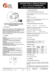
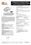
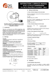
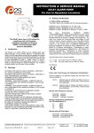
INSTRUCTION & SERVICE MANUAL
D1xS1 & D1xS2 ALARM HORNS
For Use In Hazardous Locations - Dust
3)
Ratings and Markings
The D1xS1 and D1xS2 Alarm Horns comply with the following
standards for hazardous locations:
UL 1203
CAN/CSA C22.2 No. 25-1966
The D1xS1 and D1xS2 Alarm Horns also comply with the
following standards for signaling equipment:
UL464
CSA C22.2 NO. 205-12
1)
The D1xS1 & D1xS2 alarm horns are
classified by UL as Audible Signaling
Appliances for General Signaling in
Hazardous Locations
Introduction
The D1xS1 & D1xS2 range are UL Classified alarm horns
which produce a loud warning signal in a hazardous area.
Sixty-Four first stage alarm sounds can be selected by internal
switches and each one can be externally changed to a second,
third or fourth stage alarm sound. The alarm horn may be used
for Gas applications in Class II Division 1 & 2 and Class III
Division 1 & 2 as well as Class II Zone 20, 21 and 22. D1xC1 &
D1xC2 combined alarm horn & strobe units and D1xL1 &
D1xL2 Loudspeakers are also available as well as variants for
Explosive Gas Atmospheres.
2)
Warnings
CAUTION
TO REDUCE THE RISK OF IGNITION OF HAZARDOUS
ATMOSPHERES:
DISCONNECT FROM SUPPLY BEFORE OPENING.
KEEP TIGHTLY CLOSED WHEN IN OPERATION.
WARNING
FIT SEALING FITTING IN CONDUIT RUNS WITHIN 18
INCHES FROM ENCLOSURE.
EQUIPMENT MUST NOT BE INSTALLED WITH THE HORN
FACING UPWARDS OF HORIZONTAL
3.1 Class / Division Ratings for US & Canada
Class II Div 1
Class III Div 1
FG
T6
Ta -40°C to +70°C
Ta -40°C to +70°C
Installation must be carried out in compliance with the National
Electric Code / Canadian Electric Code
3.2 Class / Zone ratings US & Canada
Zone 20 IIIB
T6
Ta -40°C to +70°C
Installation must be carried out in compliance with the National
Electric Code / Canadian Electric Code
3.3 Ambient Temperature Range:
D1xS1-DC024-D / D1xS2-DC024-D / D1xS2-AC230-D:
-40ºC to +70ºC
D1xS1-AC230-D:
-40ºC to +70ºC for 110-120Vac 50/60Hz
-40ºC to +55ºC for 120-240Vac 50/60Hz
3.4 Ingress Protection Ratings
The product is rated for ingress protection as follows:
IP rating per EN60529:
IP66
Type rating per UL50E / NEMA250:
4 / 4X / 3R / 13
3.5 Electrical Ratings per UL Listing
ATTENTION
POUR REDUIRE LE RISQUE D’INFLAMMATION DES
ATMOSPHÈRES DANGEREUSES:
COUPER L 'ALIMENTATION AVANT OUVERTURE.
CONSERVER FERMÉ PENDANT LE FONCIONNEMENT.
AVERTISSEMENT
CONDUITS DOIVENT ÊTRE SCELLÉS EN MOINS DE 18
POUCES.
ÉQUIPEMENT NE DOIT PAS ÊTRE INSTALLÉ AVEC LE
KLAXON TOURNÉE VERS LE HAUT DE HORIZONTAL.
Model No.
Nom. Voltage Nom. rms Voltage
current1
Range
D1xS1-DC024-D 24Vdc
217mA
10-30Vdc
D1xS1-AC230-D 115Vac 60Hz
230Vac 50Hz
D1xS2-DC024-D 24Vdc
77mA
53mA
924mA
D1xS2-AC230-D 115Vac 60Hz
230Vac 50Hz
268mA
159mA
Max. rms
current2
270mA @
18Vdc
110-240Vac 82mA @
50/60Hz
110Vac 60Hz
10-30Vdc
1217mA @
18Vdc
110-240Vac 293mA @
50/60Hz
110Vac 60Hz
1) Nom. rms current draw at nom. voltage and worst case tone
2) Max. rms current draw at worst case voltage and tone
__________________________________________________________________________________________________________________
European Safety Systems Ltd. Impress House, Mansell Road, Acton, London W3 7QH
[email protected]
Tel: +44 (0)208 743 8880
www.e-2-s.com
Fax: +44 (0)208 740 4200
Document No. D190-00-051-IS-SC Issue: 1
03-07-15
Sheet 1 of 6
4)
4.3 Installation procedure
Installation
4.1 Safe Installation Requirements
a. Secure the D1x alarm horn to a flat surface via the three
7mm fixing holes in the mounting bracket.
The product must only be installed by suitably qualified
personnel in accordance with the latest issues of the relevant
standards.
b. Remove the flameproof cover of the alarm horn by
unscrewing it, taking care not to damage the flameproof
threads in the process (Refer to section 5).
c. Fit an M20x1.5 suitably rated cable gland or conduit
entry into the hole in the enclosure and connect the field
wiring to the appropriate alarm horn terminals as shown
in fig. 6 (AC) or fig 8. (DC). The power supply terminals
are duplicated so that units may be connected in
parallel. An end of line monitoring resistor may be fitted
to DC units only (see section 12). If the second and
third M20x1.5 and or NPT entries are not used, suitably
rated stopping plugs must always be fitted.
The installation of the units must also be in accordance with
the NEC / CEC and any local regulations and should only be
carried out by a competent electrical engineer who has the
necessary training.
The Equipment must not be installed with the horn facing
upwards of horizontal.
The equipment has not been assessed as a safety-related
device (as referred to by Directive 94/9/EC Annex II, clause
1.5).
For ambient temperatures over +50ºC the cable entry
temperature may exceed +70ºC / the cable branching point
may exceed 80ºC. Therefore suitable heat resisting cables and
cable glands must be used, with a rated service temperature of
at least 90ºC.
To maintain the ingress protection rating and mode of
protection, the 2-off M20 and 1-off M20/NPT cable entries must
be fitted with suitably rated cable entry and/or blanking devices
during installation. If a high IP (Ingress Protection) rating is
required then a suitable sealing washer must be fitted under
the cable gland. A minimum ingress protection rating of IP54
must be maintained.
Only the flame proof cover is to be used for access to the
enclosure for installation, service and maintenance.
d. Replace the flameproof cover of the loudspeaker, taking
care not to damage the flameproof threads. Tighten
fully.
4.4 Hornless Variants
The D1x Sounder is also available as a variant with no
horn fitted in the factory. The Horn threaded nose
portion has a fitment thread of 1-3/8” – 18 UNF (to
BS1580 or ANSI B1.1). The customer is responsible for
sourcing and correctly fitting a suitable horn that meets
all of the relevant safety requirements.
5)
Access to the Flameproof Enclosure
In order to connect the electrical supply cables to the alarm
horn it is necessary to remove the flameproof cover to gain
access to the flameproof chamber. This can be achieved by
unscrewing the flameproof cover (counter-clockwise), taking
extreme care not to damage the flameproof threads in the
process.
External Earth
Stopping plug
Assembly
Connections are to be made into the terminal blocks using
solid or stranded wire, sizes 0.5-4.0mm2 / AWG 20-12. Wire
insulation needs to be stripped 6-7mm. Wires may be fitted
securely with crimped ferrules. Terminal screws need to be
tightened down with a tightening torque of 0.4 Nm / 3.5 Lb-in.
Earthing connections should be made to the Internal Earth
point on the casting.
Check that the ‘O’ ring seal is in place between the two
castings.
4.2 Mounting
(Appropriate
cable glands to
be customer
supplied)
Flameproof
cover
Fig. 2 Accessing the Flameproof
Enclosure.
On completion of the cable wiring installation the flameproof
threads should be inspected to ensure that they are clean and
that they have not been damaged during installation. Also
check that the ‘O’ ring seal is in place, on the thread diameter
in contact with the flat face of the flameproof cover. When
replacing the flameproof cover ensure that it is tightened fully.
Fig. 1 Fixing locations.
The D1x Alarm Horn may be secured to any flat surface using
the three 7mm fixing holes. The enclosure provides IP66
protection and is suitable for installation in exterior locations
providing it is positioned so that water cannot collect in the
horn, and the cable entry is sealed.
__________________________________________________________________________________________________________________
European Safety Systems Ltd. Impress House, Mansell Road, Acton, London W3 7QH
[email protected]
Tel: +44 (0)208 743 8880
www.e-2-s.com
Fax: +44 (0)208 740 4200
Document No. D190-00-051-IS-SC Issue: 1
03-07-15
Sheet 2 of 6
6)
Volume Control
The output level of the D1x alarm horn can be set by adjusting
the volume control potentiometer (see Fig 3). For maximum
output, set the potentiometer fully clockwise.
External Earth
Volume Control
Potentiometer
9)
AC Wiring
9.1 Wiring Diagrams
External Earth
Internal
Earth
STAGE 4 = S2 + S3
(Customer Supplied switches)
Stage 2
Stage 1
Tone
Selection
Dip
Switches
Fig 5a. D1xS1AC Simplified Block Diagram
Volume Control
Potentiometer
D1xS2AC / D1xS2DC / D1xS1DC / D1xS1AC
Fig. 3 Location of field controls
7)
Tone Selection
STAGE 4 = S2 + S3
(Customer Supplied switches)
The D1xS1 & D1xS2 units have 64 different tones that can be
selected independently for the first and second stage alarms.
The tones are selected by operation of the tone setting DIP
switches 1 & 2 (see Fig. 3) on the PCB. The alarm horns can
also be switched to sound the third and fourth stage alarm
tones. The tone table (Table 1) shows the switch positions for
the 64 tones on first and second stages and which tones are
available for the third and fourth stages dependent on the
Stage 1 DIP switch setting.
8)
Stage Switching Polarity (DC Units Only)
The D1xS2 and D1xS1 DC alarm horns have the facility to use
either +ve or –ve switching to change the tone to the second,
third and fourth stages. For –ve switching connect the two
headers on the pcb to the left-hand (marked –ve) and centre
pins. For +ve switching connect the headers to the right hand
(marked +ve) and the centre pins. (Refer to Fig. 4)
Fig 5b. D1xS2AC Simplified Block Diagram
9.2 Units First Stage Tones
Stage one (S1) operation: Simply connect the supply voltage to
the L and N supply terminals, (see fig. 6).
9.3 AC Units Second, Third and Fourth Stage Tone
Selection
To select the second, third and fourth stage tones on the D1x
AC alarm horns.
Stage two (S2) operation : Power L and N, link the Common-C
(D1xS2) or the Live-L (D1xS1) and S2 terminal.
Stage three (S3) operation : Power L and N, link the CommonC (D1xS2) or the Live-L (D1xS1) and S3 terminals.
Stage four (S4) operation : Power L and N, link the Common-C
(D1xS2) or the Live-L (D1xS1) and both the S2 and S3
terminals.
Positive
Switching
Activated
Negative
Switching
Activated
L L N N E E S2 S3
D1xS1AC Terminals
Fig. 4 Stage Switching Polarity
L L N N E C S2 S3
D1xS2AC Terminals
Fig. 6 AC Terminals
__________________________________________________________________________________________________________________
European Safety Systems Ltd. Impress House, Mansell Road, Acton, London W3 7QH
[email protected]
Tel: +44 (0)208 743 8880
www.e-2-s.com
Fax: +44 (0)208 740 4200
Document No. D190-00-051-IS-SC Issue: 1
03-07-15
Sheet 3 of 6
10) DC Wiring
11) Earthing
10.1 Wiring Diagrams
The unit has both a primary internal and secondary external
earth fixing point.
Internal earth connections should be made to the internal Earth
terminal (see Fig. 3 and 4. It should be fitted to the internal
earth point using a ring crimp terminal to secure the earth
conductor.
STAGE 4 = S2 + S3
(Customer Supplied switches)
Fig. 7a DC Simplified Block Diagram (negative
switching)
In addition, external earth connections can be made to the M5
earth stud (see Fig. 2), using a ring crimp terminal to secure
the earth conductor to the earth stud. The external earth crimp
ring should be located between the two M5 plain washers
provided and securely locked down with the M5 spring washer
and M5 nut.
The earth conductor should be at least equal in size and rating
to the incoming power conductors but at least a minimum of
0.82mm2 / 18AWG in size.
12) End Of Line Monitoring (DC Units Only)
STAGE 4 = S2 + S3
(Customer Supplied switches)
Fig. 7b DC Simplified Block Diagram (positive
switching
10.2 Units First Stage Tones
Stage one (S1) operation: Simply connect the supply voltage to
the + and - supply terminals, (see fig. 8).
10.3 DC Units Second, Third and Fourth Stage Tone
Selection
For units set up for –ve switching (default setting):
On D1xS1DC & D1xS2DC units, dc reverse line monitoring can
be used if required. All DC alarm horns have a blocking diode
fitted in their supply input lines. An end of line monitoring diode
or an end of line monitoring resistor can be connected across
the +ve and –ve terminals. If an end of line resistor is used it
must have a minimum resistance value of 3k3 ohms and a
minimum power rating of 0.5 watts or a minimum resistance
value of 500 ohms and a minimum power rating of 2 watts.
The resistor must be connected directly across the +ve and -ve
terminals as shown in the following drawing. The resistor leads
should be kept as short as possible.
End of Line Resistor
Stage two (S2) operation : Power +ve and –ve, link a -ve
supply line to the S2 terminal. Dip switch 2 alters stage 2 tone.
Stage three (S3) operation : Power +ve and –ve, link a -ve
supply line to the S3 terminal. Dip switch 1 alters stage 3 tone.
Stage four (S4) operation : Power +ve and –ve, link a -ve
supply line to both the S2 & S3 terminals. Dip switch 1 alters
stage 4 tone.
For units set up for +ve switching (refer to 9.1):
Stage two (S2) operation : Power +ve and –ve, link a +ve
supply line to the S2 terminal. Dip switch 2 alters stage 2 tone.
Stage three (S3) operation : Power +ve and –ve, link a +ve
supply line to the S3 terminal. Dip switch 1 alters stage 3 tone.
Stage four (S4) operation : Power +ve and –ve, link a +ve
supply line to both the S2 & S3 terminals. Dip switch 1 alters
stage 4 tone.
Fig. 9 End Of Line Resistor Placement
+ + - - S2 S3
Fig. 8 DC Terminals
__________________________________________________________________________________________________________________
European Safety Systems Ltd. Impress House, Mansell Road, Acton, London W3 7QH
[email protected]
Tel: +44 (0)208 743 8880
www.e-2-s.com
Fax: +44 (0)208 740 4200
Document No. D190-00-051-IS-SC Issue: 1
03-07-15
Sheet 4 of 6
Tone Selection – To select the required first stage tone set the tone Set DIP switch 1 (6 way DIP see Fig 3) to the required tone setting shown in the table below. The
table also shows the second stage tone can be set independently with the Stage 2 DIP switch to select the required tone. The 3rd and 4th stage tones are available if more
than two tone output stages are required, they are set/linked via the first stage tone selection.
Stage 2
Stage 3
Stage 4
Stage 1
Set DIP
Set DIP
Set DIP
Set DIP
Stage 1 & 2 DIP
Switch 2
Switch
Switch 1
Tone Description
Tone Visual
Switch 1
Switch Settings
Tone
1 Tone
Tone
Tone No
123456
(S2)
(S3)
(S2 + S3)
1
2
3
4
5
6
13
14
1000/2000Hz @ 1Hz
Singapore
15
300Hz Continuous
16
440Hz Continuous
10
11
12
17
470Hz Continuous
18
500Hz Continuous IMO code
2 (Low)
19
554Hz Continuous
20
660Hz Continuous
21
800Hz IMO code 2 (High)
22
1200Hz Continuous
23
2000Hz Continuous
24
25
26
27
28
29
2400Hz Continuous
440 @0.83Hz (50
cycles/minute) Intermittent
470 @0.9Hz - 1.1s
Intermittent
470Hz @5Hz - (5
cycles/second) Intermittent
544Hz @ 1.14Hz - 0.875s
Intermittent
655Hz @ 0.875Hz
Intermittent
30
660Hz @0.28Hz - 1.8sec on,
1.8sec off Intermittent
31
660Hz @3.34Hz - 150mS on,
150mS off Intermittent
2
3
44
010000
3
2
44
110000
4
24
1
001000
5
19
1
101000
6
44
1
011000
7
44
1
8
24
35
000100
9
34
1
100100
10
34
1
11
1
8
12
1
8
13
1
8
101100
14
3
35
300Hz
011100
15
24
35
440Hz
1s
1s
0.5s
1400Hz
1s
544Hz 0.1s
0.4s
440Hz
1500Hz
1500/500Hz - (0.5s on , 0.5s
off) x3 + 1s gap AS4428
1000Hz (1s on, 1s off)x7 + (7s
on, 1s off) IMO Code 1a
420Hz(0.5s on, 0.5s off)x3 +
1s gap ISO 8201 Temporal
Pattern
1000Hz(0.5s on, 0.5s off)x3 +
1s gap ISO 8201 Temporal
Pattern
422/775Hz - (0.85 on, 0.5
off) x3 + 1s gap NFPA Temporal Coded
100000
1s
1600Hz
544Hz(100mS)/440Hz
(400mS) NF S 32-001
1000Hz (1s on, 1s off)x7 + (7s
on, 1s off) IMO Code 1a
44
1000Hz
1.4KHz-1.6KHz 1s, 1.6KHz1.4KHz 0.5s NF C 48-265
9
2
1s
500Hz
1000Hz @ 0.5Hz(1s on, 1s
off) PFEER Gen. Alarm
8
7
1
1200Hz
1200/500Hz @ 1Hz DIN /
PFEER P.T.A.P.
500-1500Hz Sweeping 2 sec
on 1 sec off AS4428
500/1200Hz @ 0.26Hz(3.3s
on, 0.5s off) Netherlands NEN 2575
000000
1000Hz
1000Hz PFEER Toxic Gas
500Hz
0.5s 0.5s
0.5s
1.5s
0.5s 0.5s
1500Hz
500Hz
2s
1s
1200Hz
500Hz
1000Hz 1s
1s
1s
1s
1s
1s
1s
1s
1s
1s
420Hz 0.5s
1s
0.5s
0.5s
0.5s
0.5s
7s
1s
1s
1s
0.5s
0.5s
1000Hz 0.5s
111000
0.5s
3.3s
010100
1.5s
0.5s
0.5s
110100
1.5s
775Hz
422Hz
0.85s
0.5s
0.85s
0.5s
0.85s
2000Hz
1000Hz
1s
7s
1.5s
001100
111100
16
24
35
470Hz
000010
17
24
35
500Hz
100010
18
24
35
554Hz
010010
19
24
35
660Hz
110010
20
24
35
800Hz
001010
21
24
35
1200Hz
101010
22
24
35
2000Hz
011010
23
3
35
2400Hz
111010
24
20
35
000110
25
44
8
100110
26
44
8
0.1s
010110
27
44
8
0.44s
110110
28
24
8
0.57s
001110
29
44
8
101110
30
24
8
011110
31
24
8
440Hz
0.6s
0.6s
470Hz 0.55s
0.55s
470Hz
0.1s
470Hz 0.43s
655Hz 0.57s
660Hz
1.8s
1.8s
660Hz 0.15s
0.15s
__________________________________________________________________________________________________________________
European Safety Systems Ltd. Impress House, Mansell Road, Acton, London W3 7QH
[email protected]
Tel: +44 (0)208 743 8880
www.e-2-s.com
Fax: +44 (0)208 740 4200
Document No. D190-00-051-IS-SC Issue: 1
03-07-15
Sheet 5 of 6
745Hz
32
33
34
800Hz - 0.25sec on, 1 sec off
Intermittent
24
8
000001
33
24
8
800Hz @ 2Hz IMO code 3.a
(High) Intermittent
100001
34
24
8
010001
35
24
8
110001
36
24
8
001001
37
24
8
101001
38
8
19
011001
39
8
19
111001
40
24
19
0.8s
000101
41
8
19
0.6s
100101
42
8
19
010101
43
8
19
110101
44
24
19
001101
45
8
19
101101
46
24
19
011101
47
24
19
111101
48
24
12
000011
49
24
12
100011
50
24
12
010011
51
24
12
1s
110011
52
24
12
1s
001011
53
24
12
800Hz 0.25s
0.25s
0.5s
0.5s
1000Hz @ 1Hz Intermittent
0.5s
2400Hz @ 1Hz Intermittent
0.5s
2900Hz
37
32
1s
2400Hz
36
111110
0.5s
800Hz 0.25s
1000Hz
35
0.5s
745Hz @ 1Hz Intermittent
0.1s
2900Hz @ 5Hz Intermittent
0.1s
518Hz
38
363/518Hz @ 1Hz Alternating
363Hz
0.5s
0.5s
500Hz
39
40
450/500Hz @ 2Hz Alternating
554/440Hz @ 1Hz Alternating
41
554/440Hz @ 0.625Hz
Alternating
42
561/760Hz @0.83Hz (50
cycles/minute) Alternating
43
780/600Hz @ 0.96Hz
Alternating
44
800/1000Hz @ 2Hz
Alternating
45
970/800Hz @ 2Hz Alternating
46
800/1000Hz @ 0.875Hz
Alternating
47
2400/2900Hz @ 2Hz
Alternating
48
500/1200Hz @ 0.3Hz
Sweeping
49
560/1055Hz @ 0.18Hz
Sweeping
50
560/1055Hz @ 3.3Hz
Sweeping
51
600/1250Hz @ 0.125Hz
Sweeping
52
660/1200Hz @ 1Hz
Sweeping
0.25s
450Hz
554Hz
0.25s
440Hz
0.5s
0.5s
554Hz
440Hz
0.8s
760Hz
561Hz
780Hz
0.6s
0.52s
0.52s
600Hz
1000Hz
800Hz
970Hz
0.25s
0.25s
0.25s
0.25s
800Hz
1000Hz
0.57s
800Hz 0.57s
2900Hz
0.25s
2400Hz 0.25s
1200Hz
500Hz
1055Hz
3.34s
560Hz
1055Hz
5.47s
560Hz
0.3s
1250Hz
600Hz
8s
1200Hz
660Hz
1000Hz
53
800/1000Hz @ 1Hz Sweeping
800Hz
1000Hz
54
800/1000Hz @ 7Hz Sweeping
55
800/1000Hz @ 50Hz
Sweeping
56
2400/2900Hz @ 7Hz
Sweeping
57
2400/2900Hz @ 1Hz
Sweeping
58
2400/2900Hz @ 50Hz
Sweeping
59
2500/3000Hz @ 2Hz
Sweeping
60
2500/3000Hz @ 7.7Hz
Sweeping
61
800Hz Motor Siren
800Hz
1000Hz
0.14s
101011
54
24
12
800Hz
2900Hz
0.02s
011011
55
24
12
0.14s
111011
56
24
12
2400Hz
2900Hz
1s
000111
57
24
12
2400Hz
0.02s
100111
58
24
12
0.5s
010111
59
24
12
0.13s
110111
60
24
12
1.6s
001111
61
24
12
2s
101111
62
24
12
1.7s
011111
63
24
12
111111
64
21
12
2400Hz
2900Hz
3000Hz
2500Hz
3000Hz
2500Hz
800Hz
1200Hz
62
1200Hz Motor Siren
2400Hz
63
2400Hz Motor Siren
1450Hz 0.25s
64
Simulated Bell
0.69ms
__________________________________________________________________________________________________________________
European Safety Systems Ltd. Impress House, Mansell Road, Acton, London W3 7QH
[email protected]
Tel: +44 (0)208 743 8880
www.e-2-s.com
Fax: +44 (0)208 740 4200
Document No. D190-00-051-IS-SC Issue: 1
03-07-15
Sheet 6 of 6


![Manual Audition 4 [By Dr.J.]](http://vs1.manualzilla.com/store/data/005935757_1-4addafd8884e379cc6f9c4cc1fe5fdba-150x150.png)