1
~
.
.
I
L
ii,'
'.
()
CONTENTS
Specifications
4
General Description
6
Carburetors
6
Principal Parts
7
Carburetor Operation
7
Removal and Installation of Carburetor
9
Inspection and Repair
10
Assembly and Adjustment
13
Diagnosing Engine Troubles
14
Air Cleaners
17
Manifold and Exhaust System
19
Engine Governor
21
21
.Specifications
22
Principles of Operation
Removal, Inspection and Repair
23
- - - -
26
Installation and Adjustment - - - -
u
2
I
Make Yourself More Indispensable
SELL SERVICE
*
*
*
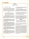
Servicemen can often sell related items or equipment by showing·
the customer how the items will be of value to him.
When you check a customer's equipment regarding the service he
asks for, you can frequently show him how a few extra service dollars
now can save him probable trouble and expense later.
A busy shop can be more efficient and a better place to work.
o
o
3
SPECIFICATIONS
0)
Tractor Series
CUB
140
240
Engine Series
C-60
C-123
C-123.
IH 3/4"
364 579 R91
9/16"
1-7/16"
1-5/8"
.032"
75
89
15
52
ZTH.68X7
366462 R92
1/2"
1-5/32"
ZTH.68X7
367 822 R91
1/2"
1-5/32"
No.20L
No.11S
45
15
35
No. 21
No.11S
50
16
35
Oil bath
Oil bath
Oil bath
One piece
None
One piece
None
One piece
None
Carburetor, Gasoline
Model
Part number *
Liquid level **
Float height **
Float drop **
Main metering jet
Idle jet
Discharge nozzle
Venturi
Needle valve seat
-
-
Air Cleaner
Type
Manifold, Gasoline
Type
Heat control
Control'spring wind
-
-
c)-,
-
"
I
Governor, Variable Speed
Engine rpm
Low idle :i: 25
Fast idle :i: 25
Rated load :i: 10
475
2016
1800
425
1575
1400
425
2200
2000
* The carburetor part number is stamped on a
metal disc riveted to
the throttle body. This number identifies the calibration for fuel
flow for a given tractor model, and must be used when selecting
replacement parts to maintain desired air-fuel ratio.
** Measurements are made from the machined face of the fuel bowl
cover to the liquid level or to bottom of float assembly. See
lllusts. 7, 8 and 9.
o
4
SPECIFICATIONS
o
340
460
560
660
C-135
C-221
C-263
C-263
ZTH.68X7
367 700 R91
1/2"
1-5/32"
No.25L
No. 118
50
17
35
IH 1-1/4"
367 258 R91
9/16"
1-5/16"
1-15/16"
.046"
75
25
28-13
45
IH 1-1/4"
367 259 R91
9/16"
1-5/16"
1-15/16"
.051"
75
27
30-13
45
IH 1-3/8"
372 723 R91
9/16"
1-5/16"
1-15/16"
.060"
75
2734-13
45
Oil bath
Oil bath
Oil bath
Oil bath
One piece
None
-
Two piece
automatic
1/4-1/2 turn
Two piece
automatic
1/4-1/2 turn
Two piece
automatic
1/4-1/2 turn
425
2200
2000
425
1980
1800
425
1980
1800
425
2640
2400
I
-
0
,
-~
o
5
GENERAL DESCRIPTION
portions to :meet the changing de:mands of
load and speed. The variable speed governor controls the carburetor throttle to
ad:rnit a greater or lesser volu:rne of airfuel :mixture. This supports the operator's
de:mand for engine speed, and provides
power to :maintain that speed, up to the
capacity of the engine.
The fuel syste:m consists, basically, of
a fuel supply tank, fuel shut-off valve, fuel
strainer, carburetor, intake-exhaust :manifold, air cleaner and a variable speed
governor.
Liquid fuel flows fro:m the supply tank
by gravity through the fuel strainer and
sedi:rnent bulb to the carburetor. Air
enters these naturally aspirated syste:ms
through the air cleaner, where dirt and
abrasive :material are re:moved.
The operation, inspection, repair and
adjust:ment of the various parts of the
fuel syste:m are covered in the followin-g ,
divisions of this service :manual section,
under appropriate :major headings.
Clean air and fuel is :metered to the
engine by the carburetor; in varying pro-
CARBURETORS
5
0>
9
Air Vent
--/-'-'~':'~:i:::::==\~~~1!-=:. : ij7fJf i ~~tAAt--r-'l'<==*===~~
~m,.;r7"'~=t=:==7-fr
12
A-55090
lIIust. 1. Cross section of a typical carburetor with identification of the principal parts.
1. Choke valve
2. Venturi
3. Throttle plate
4. Throttle stop screw
5. Idle ports
6. Idle air bleed
7. Idle jet
8. Needle valve and seat
12. Main jet adjust:ment screw
13. Well air bleed
Liquid
level
14.
Idle adjusting needle
9.
15. Metering well
10. Float asse:mbly
16. Drip hole filler
11. Main :metering jet
17. Discharge nozzle
"A" Bleed holes in discharge nozzle
6
Principal Parts
-0
While the engine is in operation, fuel
flows from the bowl through the main
metering jet to the load system or idling
system and the float valve maintains just
enough opening to sustain a constant level
of fRel in the bowL
The principal parts of a typical carburetor are shown in Illust. 1.
Carburetor Operation
~
The bowl air vent passage is a drilling
in the throttle body connecting the float
chamber with an air vent channel surrounding the venturi. Air for the bowl vent, the
well bleed and the idling system is taken
from this channel in the venturi which, in
turn, is vented to the carburetor main air
,intake. In this' manner, all air taken into
the carburetor is supplied through the air
cleaner. This not only prevents entry of
dirt and abrasives, but creates what is
called a "balanced" vent.
The function -of the carburetor is tometer the required amount of fuel to meet
varying demands of engine load and speed,
and to dis char ge this fuel into the intake
air stream in as fine a spray as possible.
o
The air-fuel ratio is not constant for
all loads and speeds. Idle and low speeds
require rich fuel mixture; full load, full
speed operation requires the leanest fuel
mixture. These modern carburetors with
their air- bleed-well method of compensation, will give these proportionate air-fuel
mixtures to meet load-'speed demands,
resulting in smooth, economical engine
performance. To simplify the explanation
of how the carburetor functions, we will
divide it into four systems and discuss
each, separately.
o
o
o
o
The ratio of air and fuel mixtur e from
a Ilbalanced" carburetor will not be serimlsly affected by changes in condition of
the air cleaner as it becomes restricted
by accumulation of dirt. A balanced type
carburetor must have an airtight seal
between the bowl and the bowl cover, since
any air admitted into the bowl other than
through the calibrated vent, will upset the
ratio of air-fuel delivery and also allow
entry of dirt.
FUEL SUPPLY SYSTEM
IDLING SYSTEM
LOAD SYSTEM
STARTING SYSTEM
In review, sustained constant level
of fuel in the bowl, together with controlled venting of the bowl, insures a stable
supply of fuel to the various metering
systems and is unaffected by the height
of fuel in the supply tank or normal operating changes in air cleaner condition.
Fuel Supply System
The fuel supply system is that portion
of the carburetor consisting of the fuel inlet strainer, fuel needle valve and seat,
fuel float, fuel bowl and the bowl air vent.
o
I
The function of the .float and fuel needle
valve is to maintain an even level of fuel
in the bowL The float assembly consists
of one or two float bodies soldered to a
float lever. This assembly hinges on the
float axle supported by a bracket on the
bowl cover. Fuel from the supply tank
enter s the bowl through the inlet strainer
and the float needle valve. As the level
of fuel ris es in the bowl, the float is
carried upward until the float lever forces
the needle valve against its seat, stopping
further inflow of fuel:
Idling System
The idling system consists of (5) idle
dis char ge port (Illust. 1), (19) idle adjusting needle, (7) idle jet and the connecting
channels and (6) air bleed. This system
controls the mixture at partially opened
throttle for idle and slow engine speeds,
until the throttle is opened sufficiently to
allow the load system to function.
Fuel for the idling system enters the
(15) well through the (11) main metering
7
L
jet and is drawn through the (7) idle jet
calibration into the idle passage where
it is mixed with air from the (6) idle air
bleed (illust. 1). The air-fuel mixture
enters the air stream past the throttle
plate, from the (5) idle discharge port.
The idle air adjusting screws on the carburetors of C-60, C-123 and C-135 engines
are turned toward their seat to enrich the
air-fuel mixture. This adjustment is re:'
verse on carburetors of C-22l and C-263
engmes, represented in lliust. 1. since
these adjusting screws control the volume
of air:"fuel mixture.
zle at a higher rate than supplied to the
(15) well by the (11) main metering jet.
This lowers the level of fuel in the (15)
welL As the load and throttle opening is
increased, the fuel level in the (15) metering well drops below a series of IIA"
air bleed holes in the discharge nozzle,
admitting an increasing amount of air from
the (13) well air bleed (illust. 1). This
metered addition of air to the discharge
nozzle is necessary to compensate for the
fact that the partial vacuum produced at
the nozzle increases out of proportion with
the increas ed velocity of air through the
venturi. Were it not for this well-airbleed compensation, the proportion of fuel
to air would rapidly increase with the
throttle opening, producing an extremely
"rich" mixture at full throttle, ftill load
operation.
Load System
The load system consists of the (2)
venturi, (17) discharge nozzle, (15) well,
(13) well air bleed, and (11) main metering
jet. The load system as the name implies,
controls the air-fuel mixture'during the
time the engine is loaded or is operating
above idle speed.
A small additional amount of fuel is
necessary to insure prompt response for
engine acceleration. When the throttle is
suddenly opened, the resulting rush of air
through the venturi picks up this neces sary
extra fuel which remains above the (11)
main metering jet in the (15) metering well
during part throttle operation.
When the throttle plate is opened a short
distance beyond the (5) idle port, lliust. 1,
a s lifficient amount and velocity of air
pas s es the (2) venturi and the (1 7) dis char ge
nozzle to draw fuel from this source. This
condition starts the load system function'"
ing. Within a partial load-speed range of
throttle plate movement, both the idling
.system and load system are delivering
fueL Further opening of the throttle plate,
due to increased engine load-speed restilts
in diminished delivery of fuel from the
idling system. Ultimately, all delivery of
fuel from the idling system is stopped and
air is being drawn from this source into
the (15) welL
0)
OJ
Carburetors on the C-221 and C-263
gasoline burning engines are equipped with
a (12) main jet adjustment screw (illust. 1)
which may be used to limit the amount of
fuel going into the engine when under light
load conditions. Some increase in fuel
economy can be obtained for periods of
light load operation in this manner. However, when heavy work is to be performed
in which the FULL POWER of the engine
IS REQUIRED, the fuel adjusting screw
must be set five turns off its seat. The (11)
main metering jet in the carburetor has
been calibrated to provide an economical,
full-power mixture and must not be restricted by use of the adjusting screw when
full power of the engine is required.
The (11) main metering jet has a calibrated opening large enough to permit the
flow of the maximum amount of fuel necessary for ftill load operation. When the
engine is stopped or idling, the level of
fuel in the (15) well and (17) discharge nozzle is similar to the level in the fuel bowL
As the load system goes into operation
with increased load and throttle opening,
the fuel is drawn from the discharge noz-
Starting System
The starting system consists of a manually operated choke valve mounted in the
8
C
. ));
o
o
carburetor main air intake. When the (1)
choke valve plate (illust. 1) is turned to
the closed position, it restricts the air
entering the carburetor. It does not, however, restrict the m.ain air vent passage.
This upsets the balance of the carburetor,
allowing the increased suction to draw
strongly upon the fuel discharge openings
when starting the engine.
Should this filler shrink and deteriorate
from. age, dirt m.ay be drawn into the engine contributing to excessive engine wear.
Should this opening be painted over or
otherwise plugged, no drainage ispos sible
and flooding with raw fuel can occur if the
fuel float valve leaks ..
I
When the outside air, m.anifold, and
engine com.bustion cham.bers are cold, it
is neces sary to supply a very "rich" starting m.ixture. Only the "lighter-ends" or
m.ore volatile portions of the fuel can be
vaporized because of the low tem.perature
and the slow m.ovem.ent of air past the dischar ge nozzle due to low cranking speed.
The necessary large quantity of fuel is
supplied by closing the choke valve during
the cranking period. As the engine fires
and engine speed increases, a springloaded valve in the choke plate opens to
let in m.or e air and lean out the "rich"
m.ixture. As the engine gathers speed
and warm.s up, the choke valve is m.anually
opened to further lean out the air-fuel
ratio to a norm.al m.ixture.
lIIust. 3. Removing the carburetor, Farmall and International 140, 240 and 340 series tractors.
An opening is provided in the bottom. of
the carburetor m.ain air intake to drain off
any excess unvaporized fuel which m.ay
return from. the m.anifold. This opening is
protected against the entry of dust and
abrasives by afelt filler. See (16),lllust. 1.
Illust.4. Removing the Carburetor, 460, 560, and 660 series tractors.
Removal and Installation of
Carburetor
Before rem.oving the carburetor from.
the engine for cleaning, inspection or
repair, clean the area and various connecting points to prevent entry of dirt into those
parts which r em.ain with the engine. Failure to perform. this sim.ple operation m.ay
result in an ultim.ate condition m.uch worse
than that which m.ade the carburetor rem.oval neces sary.
I1lust.2. Removing the corburetor, Farmall Cub and International Cub Lo-Boy tractors.
9
After the carburetor is removed, inspect the air cleaner pipe and hose for
possible air leaks wherein dirt and abrasives could enter the engine. Discard the
carburetor flange gasket. Clean manifold
flange of any scraps of old gasket which
may adhere and would prevent sealing of
new gasket.
After the carburetor is reinstalled on
the manifold, recheck the adjustment of the
governor-to- carburetor control rod to insure wide open throttle at full load demand
of governor, as follows. With engine stopped, advance engine speed control hand lever to create tension on the governor
spring; Adjust length of governor-to- carburetor control rod so that the rod slides
freely into the throttle lever, when the
throttle is wide open. Lengthen governorto-carburetor control rod by one turn in
its clevis to place spring load on throttle
lever, insert cotter pin and tighten lock
nut on clevis. Return the speed control
hand lever to a position slightly advanced
:(rom low idle position. In this condition,
check the governor-to-carburetor control
rod for any tendency toward binding. It
may be necessary to loosen the clevis lock
nut and reposition the clevis slightly to insure both ends'being in the same plane to
eliminate binding (after which the lock
nut is retightened). Refer to the division
on 'governor for coverage of governor
, adjustments.
When reinstallin'g the carburetor, care
must be used in securing air and dust tight
connections of air cleaner pipe and hos e.
Renew if necessary. Before reconnecting
the fuel line to the carburetor, remove and
clean sediment bowl and screen. Use new
bowl gasket in replacing sediment bowl.
Open the fuel tank valve momentarily to
flush line and observe for free flow of fuel.
Assemble the choke control wire and
tube, being sure full movement of choke
valve is assured with the full movement of
choke control knob.
i1....~----Nrit
o
Inspection and Repair
......f---Screen
Before disassembly of the carburetor,
clean the outside surfaces of dirt accumulations so that the solvent used to clean the
dismantled parts will not become contaminated.
c: ">'.....
.---Gasket
In order that individual parts may be
given a thorough inspection, cleaning is
important. The use of a good carburetor
cleaning solvent is necessary to dissolve
gum and varnish-like coatings commonly
found in carburetors. The slow buildup
of these coatings in jets and calibrated
openings of the carburetor restricts the
normal flow of fuel, and must be completely dissolved and removed to restore the
original fuel flow characteristics. Where
a good commercial carburetor cleaner is
~
.....
OOIIIII(F---BoWl
A·'J4754,B
lIIust. 5. Fuel strainer showing bowl removed for clean•.
ing.
10
OP
o
not available, equal ~r.ts of alcohol and
benzol maybe used.~
pr event good contact with the throttle
body bore when fuliy closed. Never use a
buffing wheel or wire brush to clean this
plate, its sharp edges must not be
deformed.
After the dismantled parts have remained
in the solvent long enough to dissolve the
coatings, remove and rinse in petroleum
base cleaning solution. Dry all parts with
compressed air, blowing through all jets
and, channels in both directions to assure
'that they are clear and clean.
When· installing the throttle plate, insert it into the shaft from the top of the
throttle body with the short end of the plate
down (measured from the holes). Insert
screws from. the -top, but do not tighten until-the throttle plate is centered in the
body bore.
Caution: Do not use drills or wires
to clean calibrated openings; any slight
enlargement of these jet openings will
affect the operation. Use only gum solvent
and compressed air for cleaning~
Unscrew the throttle stop screw until
- the plate is allowed to close fully. Holding
the shaft lightly in the closed position, tap
lightly on the face of the throttle plate with
a brass rod to jar it into a centered position. The screws may then be tightened.
The throttle plate must fit the bore closely with a minimum of light showing around
its edges. The throttle shaft must be perfectly free to turn without binding at any
point.
Throttle Body and Fuel Bowl
o
The castings should be inspected for
damage or broken flanges. Check 'mating
surfaces for warpage. Where such warpage does not exceed 0.010 inch, the surface involved may be lapped on a flatsurface using "DO" sandpaper. Clean
thoroughly after the sanding operation.
Clinch over the expos ed end of the
throttle plate screws to lock them in place.
This can be done by clamping a 1/4-inch
square rod vertically in a vise, and locating the throttle body on the rod through the
venturi to bring the -end of the rod directly
under the end of each of the throttle screws
in turn. A flat end punch can then be
tapped against the outer end of the screw.
This must be done with care to prevent
distortion of throttle shaft or plate.
Normal clearance between the choke
shaft and bowl casting bore is 0.002 to
0.005 inch. Where use of a new shaft will
still result in a shaft clearance of 0.007
inch or more, the bowl casting should be
replaced. Excessive wear at this point
makes it impos sible to seal out dirt at the
seals.
The normal clearance between the
throttle shaft and throttle body bore is
0.001 to 0.003 inch. Where the use of a
new throttle shaft will not hold the clearance below 0.005 inch; the throttle body
assembly should be replaced. Excessive
wear of this throttle shaft bore will result
in dirt and air leakage past seals and poor
alignment of the throttle plate, affecting
engine idling and governor action.
Float Assembly
Replace the float assembly if float is
loaded with fuel or if the float lever axle
bearing is worn excessively. Inspect top
side of the float lever for wear wher e it
contacts the fuel needle valve.
Throttle Plate
o
The float axle should be replaced if
any wear can be detected on its bearing
surfaces.
The throttle plate should be inspected
for burrs or damaged,edges which would
11
I
Fuel Needle Valve and Seat
Venturi
If any wear can be detected on the valve
face, the needle valve and seat asse:mbly
should be replaced. The float asse:mbly,
its axle, and the fuel valve are responsible
for :maintaining a stable and correct fuel
level; all parts :must be :maintained in good
condition. Only slight bending of the float
lever should be necessary to secure the
correct float height. The float lever stop
where used, should be adjusted to control
float drop. Proper setting of float drop
prevents the float fro:m striking and wearing on the botto:m of the bowl when operating over rough terrain.
Floataxle~
A-3J93S:
IIIust.6. Float assembly and fuel needle valve removed
from carburetor.
o
lIIust.8. Float measurements and liquid level Zenith
68X7 carburetor, 140, 240 and 340 series C·123
and C·135 engines.
13"
132"
/
Iii"
1 32
Main metering jet
A-23164A
.lIIust.9. Float measurements and liquid levellH 1·1/4",
1·3/8" carburetors 460, 560 and 660 series
C-221 and C·263 engines.
IIIust. 7. Float measurements and liquid level, IH 3/4"·
carburetor Cub series C·60 engine.
12
C~·
);p
o
Adjusting Screws and Seats
Assembly and Adiustment
The idle adjusting needle ,point must be
smooth and free from grooves, caused by
being closed forcibly agaiIist;its seat.
Where this condition is found, a new screw
should be used.
Upon reassembly of the carburetor, be
sure all new gaskets and seals are used
throughout and are properly installed to
insure gas tight connections. Use care"
when assembling fuel bowl to throttle body
to prevent damage to the float assembly or
the idle jet tube.
The main jet adjusting screw (where
used) and seat should be inspected for
damage caused by the screw having been
forced against its seat. Where evidence
of this is found, both the s,crew and seat
should be replaced. Service tool Number
HC-80 is used to remove the main adjusting screw seat. The old seat must not, in
any case, be reinstalled since the removal
operation will destroy the tapered seat and
the calibrated opening. The opposite end
of the Number HC-80 tool is used to drive
1:he new adjusting screw seat into place in
the carburetor bowl casting (see lllust. 10).
o
When replacing the idle adjusting screw
and the main jet adjusting screw, turn them
down carefully until lightly seated. Then
back them up to approximately one turn
open for the idle screw and five "turns open
for the main screw. Forcible seating of
these screws will result in damage to the
tapered face of the s crew and to its seat.
The throttle stop screw sho.uld be set to
hold the throttle plate slightly open. These
settings of the idle screw and the throttle
stop screw serve only as a starting point
for idle adjustment.
Adjustment of the carburetor should not
be attempted until the engine has reached
normal operating temperature. Then adjust throttle stop screw for the specified
low idle speed and set the idle adjusting
screw for smoothest engine operation.
Advance the engine speed control lever for
a few seconds and again idle the engine,
rechecking the idle adjustments for specified low idle speed and smoothest operation.
Venturi and Jets
Inspect the venturi, jets, main adjustingscrew seat, and other calibrated openings for possible damage from improper
probing in previous cleaning operations.
Use the carburetor identifying part number to be found stamped on a metal disc
riveted to the throttle body when selecting
replacement parts. Make sure you are
using the parts catalog for the tractor and
engine involved and that parts selected are
from list headed with the carburetor identifying parts number. 'Failure to take this
precaution when renewing parts could result in a carburetor completely out of
calibration and an operation lacking power
or economy.
Where gasoline carburetor is equipped
with a main fuel adjustment screw, its only
function is to limit the fuel going to the
engine for greater economy when unit is
to be us ed for extended periods under
light loads. Where heavy work is to be
performed, in which the full power of. the
engine is required, this main fuel adjust~g screw must be set five turns off its
seat. The main metering jet which forms
the fuel adJustment screw seat, has been
calibrated to provide a full-power mixture and must not be restricted by use of
the adjusting screw when the full power
of the engine is required. The main fuel
adjusting screw packing nut should be
tightened sufficiently to prevent leakage
and to hold screw firmly in position.
"=~==""~". .~!:~
A-5509i
()
lIIust. 10. Service tool No. He-SO for installing and removing main adjustl,!g scmw seats, 460, 560
and 660 tractors.
13
/
Legend for must. 11
1.
2.
3.
4.
6.
7.
8.
9.
10.
11.
12.
13.
14.
15.
17.
18.
19.
20.
Location of the
carburetor number
--
21.
22.
23.
24.
25.
26.
27.
28.
29.
30.
_-30
Gasket, carburetor
Shaft, throttle valve
Spring, retainer, idle set screw
Plate, throttle valve
Body assembly, throttle
Gasket, fuel bowl
Gasket, needle valve cage
Needle valve assembly
Idle jet
Axle, float
Nozzle, discharge
Retainer, choke shaft seal
Seal, choke shaft
Spring, choke lever
Filler and plug, drip hole
Plate, choke valve
Retainer, throttle shaft seal
Seal, throttle shaft
Strainer screen
Valve, idle adjusting needle
Spring, retainer, idle adjustment
Float assembly
Gasket, discharge nozzle
Bowl assembly
Gasket, main jet
Jet, main metering
Shaft, choke valve
Air bleed, main
18,
'~
It---~ •
16"
....., .....
,
Diagnosing Engine Troubles
Servicemen should not be too quick in
condemning carburetor operation. Poor
fuel economy, 10 s s of power, poor recovery
from overload, or poor acceleration are
not necessarily results of inadequate carburetion. Fuel system conditions that can
affect fuel economy, while important, are
relatively few in number. Make sure that
none of the following conditions exist; but
don1t limit your investigation to the fuel
system.
IPI-3OIIC
IIlust.11. Exploded view of IH 3/4" carburetor, Cub series tractors.
14
Legend for lliust. 12
.~~.~ --~--l
o
U-0<
-
-
-- -
2
1.
2.
3.
4.
5.
7.
• 8.
9.
11.
12.
13.
14.
15.
16.
18.
19.
20.
21.
22.
22A.
23.
24.
25.
26.
27.
28.
29.
31.
32.
33.
34.
35.
36.
37.
38.
39.
40.
41.
o
25-.... -....
26--
-
~
/./!
25
!'~'i497!,-
Illust. 12. Exploded view of Zenith 68X7 carburetor, 140,
240 and 340 series tractors.
4. Poor setting of idle or main adjustments to match fuel or to meet a continuing load condition.
Fuel system conditions affecting fuel
economy:
1. Float valve leakage or high fuel
level.
2.
Gasket, carburetor
Elbow and strainer assembly
Valve, idle adjusting needle
Spring, retainer idle adjustment
Body assembly, throttle
Seal, throttle shaft
Retainer, seal
Shaft assembly, throttle
Screw, throttle stop
Gasket, fuel Valve
Needle valve assembly
Axle, float
Tube, idle filler
Bowl assembly, fuel
Plug
Gasket, plug
Jet, main metering
Gasket, main jet
Plug, drain
Cock, drain
Filler, drip plug
Plug, choke shaft hole
Screw, choke plate
Plate, choke
Seal, choke shaft
Retainer, seal
Bracket assembly
Shaft, choke
Gasket, discharge nozzle
Nozzle, discharge
Air Bleed, well vent
Float assembly
Gasket, bowl
Screw, throttle plate
;Plate, throttle valve
Venturi
Jet, idling
Plug, throttle shaft hole
5. Failure to return choke valve to full
open position.
Damaged or enlarged jet openings.
6. Plugged air intake and/or air cleaner.
3. Unbalanced conditions due to bowl
gasket failure or dirt-plugged air bleeds
or vents.
7. Failure of manifold automatic heat
control.
15
"
other factors that can influence fuel
economy:
5. Air leakage between carburetor and
manifold or between manifold and intake
valve ports, or cracked intake manifold.
1. Loss of engine compression due to
piston anCi.:'fing condition or valve leakage.
Note: Conditions where engine would
draw in unfiltered air will also result in
rapid and excessive engine wear from dust
and abrasives.
2. Improper valve timing.
3. Loss of valve lift due to cam wear
or valve lever adjustment.
6. Carbon or coke in intake manifold,
at hot spot or heated jacket, restricting
the amount of air-fuel mixture available
to the engine.
4. Unsatisfactory operating temperature due to water pump or thermostat
failure, etc.
7. Exces sive clearance between throttle
shaft and throttle body.
5. Spark plug burning or fouling.
6. Ignition-timing error.
8 .. Poor governor action due to wear,
misalignment or binding of moving parts.
7. Misfiring-due to poor condition of
ignition system.
8.
9. Pluggea air intake and/or air
cleaner.
Use of high viscosity engine oil.
10. Failure of manifold automatic heat
control.
9. High friction loss in transmission
or final drive due to lack of, or improper,
lubrication.
Other conditions influencing power
loss:
10. Brakes dragging.
11. Excessive drive wheel slippage due
to worn lugs or lack of sufficient wheel
weights.
1. Loss of engine compression due to
piston blow-by or valve leakage.
2. Valve timing error.
12. Improper adjustment of implement,
resulting in excessive draft requirement.
3. Excessive intake valve stem and
guide clearance.
13. Excessive drive belt slippage, in
belt driven applications.
4. Loss of valve lift due to cam wear
or valve lever adjustment.
Fuel system conditions affecting power
loss:
1.
5. Ignition timing error.
6. Detonation or surface-ignition due
Low fuel float level.
to:
(a) "Hot spots" in the combustion
chambers, exposed sharp corners or burned spark plugs.
2. Obstructed fuel passages, jets or
screens from dirt or fuel gum.
3. Obstructed air bleeds in carburetor.
4. Lean setting of idle and main adjust- ..
ments.
16
(b) High altitude piston equipment
used in altitudes below that for
which they were designed.
o
10. High pressure loading of hydraulic
rower supply.
(c) Use of fuel having toq Iowan
octane rating.
11. Slippage of drive wheels or drive
belt.
7. Misfiring due to poor condition of
ignition system or loss of engine compression.
12. High friction losses in transmission
of power.
8. Unsatisfactory operating temperature due to condition of cooling system.
13: Indicate.d power loss, due to improper adjustment of implement and resulting excessive draft requirement.
9. Plugged exhaust system, muffler or
spark arrester.
AIR CLEANERS
o
Oil-bath type air cleaners protect the
engines from entry of dust and abrasives
only so long as they are properly maintained. The Operator's and Preventive
Maintenance Manuals instruct the operator
to "remove, clean and refill the oil cup
every day, or after every ten hours of
operation (more frequently when operating
under dusty·conditions)." The frequency
•
of this cleaning under dusty operating conditions to be governed by the dirt build-up
found in the Cleaner oil cup. Again quoting the Operator1s and Preventive Maintenance Manuals, "Never allow dirt to
build up in the cup more than one-half inch·
deep. II II Mter every fifty to sixty hour s of
operation, the entire air cleaner should be
removed, disassembled and thoroughly
washed. II
::.':.
~'~-----in~~e
cap
. I
o-----..
.
Screen
Hose
-~~support .
~.'
clamps.;
~Oil
cup
baffle
IIlust. 13. Exploded view of typical air cleaner, Formal!
and International series.
lIIust. 14. Exploded view of typical air cleaner, utility
series.
17
I
Collector pre-cleaners are available
as special attaclunents for us e in very
dusty operating conditions to assist in
extending the period of us e between necessary cleaning and servicing. The collector pre-cleaners are used on the type
of cleaners shown in Illust. 13 and replace
the air intake cap.
must. 17 shows air entering the air intake pipe through the regular cap where
the heavy screen prevents entry of large
particles of trash. The air then passes
down to the oil cup, where it is drawn
through. the oil bath. As the air passes
up through the screens above the oil cup,
some oil is carried up with the air, coating the screens. Fine dust and abrasives
are removed on contact with the oiled
screens. As the oil drains back down
from the screens, dirt is flushed back
down to settle to the bottom of the oil cup.
I
j
j
!
j
Crankcase breather
connection
lIIust. 15. Collector-type pre.c1eaner disassembied for
cleaning.
Pre- screener attachments are available
for use where a considerable amount of
leaves or coarse dirt is encountered to
assist in extending the period of use between necessary cleaning of air intake
cap. These attaclunents replace the regular air intake cap on the type of cleaners
shown in Illust. 13.
5
~---===:--~"'--------"""\
Body assembly
Oil cup
retaining clamP ......
assembly
~~~~
Oil level
Oil cup assembly
~
Dusty.air
Partially clean ·air
-Clean air
o ~ Dust particles
§ Air bubbles
~Oil drops
~
A-32102A
,6
"
Illust.17. Cross section of a typical air cleaner showing
movement of air and oil in the unit.
The efficiency of the air cleaner is at
its best when oil and screens are clean;
this efficiency drops rapidly as the oil
and screens become loaded with foreign
material.
A-f7408
Proper and efficient functioning of the
air cleaner is an important factor in s ecuring maximum power and maxirnum
engine life. A most careful inspection
Illust.16. Disassembled (5) two-piece and (6) one-piece
types of pre-screener attachments, to provide
a greater intake screen area.
Ii
I
~~~
I---"Ici.)_
18
QJ.
.....
.•
:,
o
of the air cleaner and its co=e~tions
should be a part of each engine tune-up
o-r m.ajor engine overhaul. A sm.all air
leak which would allow the engine to draw
in unfiltered, dirty air will result in rapid
engine wear and .early failure. A partly
plugged air cleaner has a throttling effect
on the engine resulting in loss of power
and lowered fuel econom.y. These conditions would have a bad effect on an
otherwise satisfactory tune-up or overhaul
job.
o
The use of heavier oil than recom.m.ended for the season of use in the air cleaner
will also result in a throttling effect sim.ilar to a plugged cleaner. Too heavy an
oil in the air cleaner pres ents a problem.
in cold weather starting of the engine,
since it lim.its the available air-fuel m.ixture. The use of too light an oil viscosity
for the season of use will result in som.e
carry-over of oil into the engine. This
leaves too Iowan oil level in the cleaner
cup to provide good air filtration.
/
MANIFOLD AND EXHAUST SYSTEM
The exhaust and intake m.anifolds for
the C-60, C-123, and C-135 gasoline burning engines are com.bined in a single casting. A sm.all area located at the top of the
intake ris er is heated from. the exhaust
gas es, which as sists in vaporizing the
droplets of fuel without adding m.aterially
to the tem.perature of the air-fuel m.ixture.
OJ
!
The exhaust and intake m.anifolds for
the C-22l and C-263 gasoline burning engines are of two piece construction. The
intake m.anifold riser is jacketed for circulation of exhaust gases to assist in vaporization of fuel. A thermostatically controlled valve allows circulation of hot
exhaust gas es to the intake jacket during
engine warm. up period. As them.anifold
approaches a norm.al operating tem.perature, the therm.ostat closes the control
valve, reducing the heat applied to the
intake jacket. The control valve is counter-balanced and m.ust m.ove freely in its
m.ounting to be actuated by the bim.etal
t:
~
4--~
A-49496
- lIIust. 18. C·135 engine manifold with vertically mounted
exhaust muHler; th~ C·60 and C·123 are similar.
19
-
/
/1-.
/ i.
thermostat spring. At room temperature
the thermostat spring will be wound 1/4
to 1/2 turn when hooked to its anchor pin
and with the control valve open.
of heat from the effective surfaces, and
also restrict the amount of air-fuel mixture available to the engine through the
reduction of the internal diameter of the
manifold. Either. condition will result in
loss of power and unsatisfactory operation.
Correction is by removal of the deposits.
Extremely heavy deposits may result in
uneven expansion and cracking of the manifold casting, requiring replacement of the
part.
With extended use, the heat control
valve parts may burn and blister and tend
to become inoperative. Should the valve
stick open, some loss of power and economy will be experienced due to application
of excessive heat to the intake manifold.
Should the valve stay in the closed position,
the lack of heat on the intake manifold will
cause slow warm up and require extended
us e of the choke valve.
Manifold gaskets must be in good condition to prevent entrance of dirt and
abrasives into the engine and to maintain
the air-fuel ratio of the intake mixture.
To prevent overstressing of studs and to
insure even compression of the gaskets,
the stud nuts should be tightened to specifications with a torque indicating wrench.
On the four- cylinder engines the manifold
to engine stud nuts should be tightened to
20-25 ft. lbs. On six-cylinder engines
covered ip. this section, the manifold to
engine stud nuts should be tightened to 2030 ft. lbs. The four bolts attaching the intake and exhaust halves of the six cylinder
manifold should be tightened to 25-30 ft.
lbs.
Extended use of either the one-piece
or two-piece manifolds may result in
carbon or coke-like deposits in the heated
area of the intake manifold. Such deposits
act as an insulator, preventing the transfer
7r
6-~
After removal and replacement of
intake and exhaust manifold assembly,
for any reason, it is advisable to re-check
the carburetor throttle position in relation
to governor position. This is neces sary
due to possible change in center-to-center
distance between governor and carburetor;
see number 1 adjustment "Synchronizing
the Governor" under heading "Governor
Installation and Adjustment. 1I
10
~9
4
Exhaust mufflers in vertical and underslung mountings are used on tractors covered by this section. Some applications
of these tractors may call for the use of a
spark arrester attachment as insurance
against fire hazards from exhaust sparks.
These items require no servicing but
should be examined from time to time for
damage which would restrict the exhaust
of the engine. ·Such restriction would
cause loss of power and reduce engine
valve life.
~I(
5
4
.~
3~
~-7
A-5307BA
lIIust. 19. C·221 and C·263 engine manifold showing con·
struction of automatic heat control valve.
20
o
o
Specifications
Tractor Series
CUB
140
240
340
460
560
660
Engine Series
C-60
C-123
C-123
C-135
C-221
C-263
C-263
- -
"A"
"A"
"A"
--
-
Governor Spring
Use rockshaft lever hole
-
-
-
.
Sp:dng number
251 464 Rl 46944 DA 369 686 R2
369 686 R2
367 739 Rl
367 7;'9 Rl
372709'Rl
Outside diameter
.6250"
.5625"
.7700"
.7700"
.8125"
.8125"
.8125"
Wire size
.0915"
.080"
.0915"
.0915"
.0915"
.0915"
.1055"
Number of coils.
8-1/2
15
6
6
15-1/2
15.. 1/2
14-1/2.
Yes
Yes
Yes
Yes
No
No
No
Bumper spring
(i)
.
:I'D
Governor weight
to pin clearance
.001-.004" .001-.004" .001-.004"
.001-.004"
.001-.010"
.001-.010"
.001-.010"
475
425
425
425
425
.
Engine rpm
Low idle :1:25
o
<
In
425
425
,-
Fast idle :1:25
2016
1575
2200
2200
1980
1980
2640
Rated Load :1:10'
1800
1400
2000
2000
1800
1800
2400
Z
o
:I'D
Principles of Operation
When a change in load occurs, there is
a m.om.entary change in engine speed. This
causes the governor weights to m.ove inward or outward, thereby opening or closing the throttle sufficiently to m.aintain a
reasonably constant engine speed up to the
full load capacity of the engine. The speed
variation between fast idle and rated load
speed will norm.ally be about 10 percent
in these tractor governors.
The engine governors us ed with the
carbureted engines covered in this section
are all of the fly-ball, variable-speed type.
They are designed to m.aintain a selected
engine speed within reasonably constant
lim.its under varying load conditions, by
proportioning the fuel to the load.
For its action, the governor depends
upon centrifugal force developed by
weights rotating about a shaft. A variable
governor spring is used to counteract the
centrifugal force or <;mtward m.ovem.ent of
the weights. Thism.ovem.ent of the governor weights, through suitable linkage, controls the carburetor throttle opening.
Adjustm.ent is provided in the linkage
between the governor and the carburetor
to synchronize the position of the throttle
with a position of the governor weights.
This adjustm.ent is m.ost im.portant, since
it insures the full power response of a
wide open throttle when the governor
weights are collapsed by the reduction
in speed due to application of a full load to
the engine.
When the operator starts the engine
and sets the engine speed control lever
for a desired speed, the governor weights
m.ove outward with the increasing speed
until the centrifugal force on the weights
counterbalances the tension of the governor spring. When this condition is reached,
the carburetor throttle has also been
m.oved to a position where the air-fuel
m.ixture adm.itted is sufficient to m.aintain
this desired speed.
In review: With an engine supporting
its load and m.aintaining a desired governed speed, three factors have reached
an aIm.ost perfect balance. These are the
forces of (1) governor spring tension (2)
centrifugal force on governor weights,
counteracting the effects of (3) load on the
engine speed. Slight changes in load
(within engine capacity) will cause slight
changes in engine speed, upsetting the balance of forces and thereby opening or
closing the carburetor throttle until the
forces are again brought into balance.
The operator controls engine speed by
use of the engine speed control lever, increasing or decreasing the governor
spring tension -- not by direct connection
with the carburetor throttle valve.
Increasing the governor spring tension
m.oves the governor weights inward which,
in turn, m.oves the throttle further open,
thereby increasing the engine speed until
the increased centrifugal force of the governor weights counterbalances the greater
spring tension.
To insure sm.ooth, surgeless, and
prom.pt response of the governor, all of
its m.oving parts and linkage m.ust m.ove
freely to follow slight changes in engine
load- speed. Should binding occur at any
point, a greater change in speed will take
place before sufficient c-;-ntrifugal for~
or spring tension is built up to overcom.e
the friction and m.ove the throttle valve.
Friction increases and binding often
occurs because of wear and m.isalignm.ent
of the carburetor throttle shaft. Sludge
deposits in the governor housings can
Decreasing the governor spring tension
allows the centrifugal force to m.ove the
weights outward, closing the throttle and
thereby decreasing the engine speed until
the decreasing centrifugal force and the
reduced spring tension again balance each
other.
22
0);
Q)
r
caus e sluggish or rough action of govern?r
ing parts and examine each for damage or
parts and linkage. Wear of governor
excessive wear. No attempt should be
weights, pins, sleeve, rocksp.afts, or rock- ... made to salvage old gaskets or seals.
shaft lever also result in surging and erThey should be carefully removed from
the assembly and replaced with new to
ratic g.overnor action.
insure an oil tight, dust proof operation.
Removal, Inspection, and Repair
Where sludge accumulations are found
in the gm.~ernor housing, corrosion of
bearing surfaces may have occurred.
These rough bearing surfaces and their
increased frictional drag are responsible
for poor governor action. Excessive
bearing clearance also results from
sludge corrosion.
In the four cylinder engine governors,
the governor drive gear also serves as
the ignition unit drive. These governor
drive gears are marked for proper mesh
with mating gears at top dead center of
number one cylinder compression stroke.
Some reassembly time may be saved if
the engine is turned to this position before
removal of the governor assembly.
o
Note: Moisture and sludge accumulations in the engine indicat e that the engine
has been runnmg over long periods of time
below normal operating temperature.
Thermostat operation should be checked
on those tractors so equipped and the
tractor operator informed on his need to
maintain operating temperature.
Before removing any of the governor
assemblies for inspection or repair, clean
the surrounding area and the various connecting points to prevent entry of dirt into
thos e parts which remain with the engine.
After disassembly of the governor, start
the cleaning of parts with a clean container
of clean solvent. Wash ball bearings first.
Do not spin bearings while washing. Turn
them slowly back and forth while dipping
the bearing up and down in the solvent to
dislodge dirt. Blowout with compressed
air, holding the parts to prevent the air
blast from spinning them, to avoid possible scratching of balls and grooves.
Flush again in clean solvent and blow-dry
a second time. Examine under good light
to determine if further cleaning is necessary. Add a few drops of oil to the balls
and grooves, then, and only then, spin ~
hand to test for roughnes s and wear.
The decision on what new Earts should
be used to rebuild the governol- assembly
will be bas ed upon the wear found and the
condition of the following groups of parts:
1. Weights, pins, and weight carrier:
Clearance in excess of 0.003 inch over
that specified between pins and weights or
carrier.
2. Governor shaft bearings and thrt:3t
bearing: Rough, pitted bearing surfaces
of either plain or ball type bearings.
3. Rockshaft, rockshaft fork, bearings
and levers: Worn or damaged rockshaft,
rockshaft fork or spring levers. Rough,
pitted bearings and bearing surfaces.
Wash and clean the remainder of the
rotating parts in solvent, examining the
weights, carrier and weight pins for
damage or wear. Clearance between new
weights and new pins for each governor
are shown on specification page. Clearances found to exceed those specified by
0.003 inch or more would be considered
excessive and parts should be renewed.
Wash and clean
th~
Where all three conditions are found,
the use of new complete governor assembly should be considered, since the few
parts which can be salvaged may not cover
the labor cost of overhaul.
Where conditions 1 and 2 are involved,
the rotating assembly, including new bearings, weights and pins, should be used.
housing and remain-
23
I
L
_
/
Where only the governor weight and pin
clearance is found questionable, only these
individual parts need be replaced. In all
cases ~ gaskets and new seals m.ust be
used to prevent entry of dirt and lost of
oil.
4A
Exam.ine hook ends of governor springs
and m.ating holes in spring lever s for
wear. Replace these parts where appreciable wear is found.
Care m.ust be taken in the reassem.bly
6
9 10
fr4J
I
I
I
I
I
1
t
11
I
t
I
ilQ
.1
3---~
2---~
I
I
4B
I
' ' - - - - - ' vr
AI
-----'
4
8-8259
lIIust.20. Exploded view of C·60 engine governor.
1-2-3.
4-5.
6.
7.
8.
9.
10.
11.
12.
13.
14.
15.
Governor to carburetor control
rod
Rockshaft extension and bracket
Key
Governor spring
Rockshaft and spring lever
Rockshaft oil seal
Rockshaft bearing
Governor speed change lever
Lever shaft
Maxim.um. speed stop screw
Housing cap screw
Housing expansion plug
16.
17-18.
19.
20-21.
22.
23.
24.
25.
26-27.
28.
29.
24
Governor shaft front bushing
Bum.per spring and adjustm.ent
Dowel pin
Housing and gasket
Sleeve retainer ring
Thrust ball bearing
Thrust sleeve
Governor rear bushing
Governor weights and pins
Governor shaft, carrier and
base
Rockshaft f01'k
o
of the governor rockshaft, rocksh.ci.f~ fork,
bearings and seal to insure linif.orm.ly
sm.ooth m.ovem.ent of the rockshaft from.
one extrem.e of m.ovem.ent to the other.
Lubricate the rockshaft oil seal thoroughly
upon installation. Som.e slight friction
resulting from. drag of the oil seal on the
shaft is unavoidable, but friction from. any
other source m.ust be held to a m.inim.um..
Any rough, jerking m.ovem.ent of the rockS'haft m.ust also be elim.inated to prevent
s'ur ging and erratic governor action.
Governor shaft end clearance is adjusted in the C- 60 engine governor by placing
0.020 inch thickness of feeler gauge stock
I
21
I
I
I
I
I
I
2
22
\
\
\
o
\
\
34
A-49502
lIIust.21. Exploded view ofC·123 and C·135 engine governor.
1-2-3.
4.
5.
6.
7.
8.
9.
10.
11.
12-13-14.
15.
16.
17.
18.
Governor to carburetor control rod 19.
Governor speed change lever
20.
Governors pring
21.
Oil seal
22.
23.
Washer
Governor spring lever
24.
Maxim.um. speed stop screw
25.
Housing cap screw
26.
27-28-32.
Housin,g
Oil filler cap
29.
30-31.
Rockshaft needle bearings
Plug, expansion
Rockshaft bushing
33.
34.
Rockshaft s ~al
25
Seal retainer
Rockshaft fork
Rockshaft
Drive gear, carrier and shaft
Governor weights
Thrust sleeve
Thrust ball bearing
Governor shaft spring
Bum.per spring and adjustm.ent
Weight pins
Governor shaft thrust and
stop pins
Rockshaft retainer pin
Gasket
1
i
I
between drive gear and governor base
when pressing the gear on the assem.bly.
After gear is pressed in place, the end
cLearance should be within the range of
0.020 to 0.025 inch. See Illust. 28.
Installation and Adiustment
Install the C- 60 engine governor - ignition drive oil seal with seal lip facing
forward; the seal m.ust be square in the
crankcase bore and positioned 23/32 inch
in from. the ignition m.ounting flange face.
See lliust. 23. The seal m.ating surface
on the outside diam.eter of the gear hub
m.ust be sm.ooth and free of cuts or
scratches to prevent rapid wear or dam.age to seal lip. Any sharp edges on gear
hub slots should be rem.oved to prevent
dam.age to seal during installation of governor as s em.bly.
End clearance in the C-123 and C-135
engine .governor shaft is elim.inated by the
(26) governor shaft spring and thrust pins
used in its design. See musts. 21 and 29.
In the C-22l and C-263 engine governor,
the internal fit of the (25) governor shaft
ball bearing controls its end clea--rance.
See lliusts. 22 and 30. A new ST 552 ball
bearing will have end clearance in the
range of 0.004 to 0.0065 inch.
This
bearing should be replaced when, after
thorough cleaning, it is found rough.
1
2
3
9
\~ ~\~
l-e [//
~
~
0
_
"
\
\.
7
Install the C-60 engine governor assem.bly and ignition unit using new m.ount-
8
/10 11 12
0
14
/19
21 23 25
27
15 16 17 \ 20 / 22 / 24 I 26 \
U///
28
29\
\
_"J/ / ! ! / /~8
!
j ®' \ \ ~\
~'~~C$,.i
· Jf, A ~/( ~ -i t
h
W I ~ ,~~)~Ttll Do '&1 J~U~ GlID ~
00
4,
\. \
0
A-53077B
13
12
.
~20
IIIust. 22. Exploded view of C-221 and C·263 engine governor.
1-2-3.
4.
5.
6.
7.
8.
9.
10.
11-12.
13.
14-15.
16.
Governor to carburetor control.
rod
Governor speed change rod
Bracket
Maxim.um. speed stop adjustm.ent
Governor spring retainer
Governor spring
Lever and rockshaft assem.bly
Oil seal, rockshaft
Bushings
Plug, expansion
Housing and gasket
-(Rockshaft fork
17.
18.
19.
20.
21.
Z2.
23-.
24.
25.
26.
27-28.
29.
30 •
..;.-, ...
26
Set screw
Thrust ball bearing
Sleeve retainer ring
Governor weights
Thrust sleeve
Carrier retainer ring
Carrier
Bearing retainer ring
Governor shaft ball bearing
Bearing retainer
Governor shaft and key
Drive gear
Com.plete rotating assem.bly
o
I
o
IIIust. 23. C·60 engine, locating governor· ignition drive
oil seal in crankcase.
IIlust.24. C·60 engine, installing governor assembly(seal omitted to better illustrate gear mesh).
ing gaskets, insure proper ignition timing
as follows:
Center mark on fan drive pulley aligns
with pointer while hand cranking engine;
(See lllust. 26.)
c··
1. With the engine positioned at top
dead center of nwnber one cylinder firing
stroke, locate the single punch mark between teeth of idler timing.gear. Use
chalk to mark top surface of two teeth on
each side of punch mark.
2. Chalk the rear end of the punch
marked tooth on the governor drive gear.
3. Install the governor assembly,
meshing the marked gear teeth as shown
in lllust. 24.
4. Position the ignition unit distributo.:p
rotor arm and (A) drive shaft lugs for fir'ing nwnber one cylinder. See lllust. 25.
Install ignition unit on engine, meshing (A)
lugs and (B) drive slots.
5. Advance or retard ignition distributor, until spark occur·s as the Top Dead
II lust. 25. Assembling the ignition unit to engine, with
unit and engine in No.1 firing position.
27
cI
i
Ii
4. Advance or retard the ignition dis.,.
tributor, until spark occurs as Top l)ead
Center mark on fan drive pulley align~"
with pointer while hand, cranking the' engine'. -See must. 27.
II
!
!
I
I
I
I
I
I
lIIust. 26. C·60 engine timing pointer and timing marks.
Illust.27. C·123 and C·135 engine timing pointer and
timing marks.
Install the C-221 and C-263 engine governor assembly using new mounting gaskets. The governor drive gear may be
meshed in any position, in thes e engines,
since ignition unit is not involved in the
governor drive.
Install the C-123 and C-135 engine governor assembly and ignition unit using
new mounting gaskets, insure proper ignition timing as follows:
1. With the engine positioned at top
dead center of number one cylinder firing
I"'" ~
stroke, insert governor pinion with com~~.C::,·:' --"plete'rotating assembly into the crankcase,
;:'.
nie.shing the marked tooth on the cam gear
with the marks between teeth of the governor pinion.
Mter installation of either new or overhauled governor a~semblies in the engines
covered ~ this manual section, it is important that a thorough check of all four
adjustments be made. The basic governor
assembly may be in perfect condition, but
in order to insure its full range of control
it must be adjusted to its individual engine.
2. Install the governor housing assembly, being sure first that the governor
spring is properly assembled. See must.
29. See also that the governor shaft spring
and thrust pin is in place in the front end
of the shaft.
,
J:
1. Synch;ronizing the governor-tocarburetor throttle movement.
Because of possible change in centerto- center distance between governor and
carburetor, due to removal and replacement of manifold, carburetor or governor
assemblies, the linkage between the governor and carburetor must be adjusted to
establish the throttle position in relation
to governor weight position. This adjust-
. 3. Position the ignition unit distributor
rotor arm and (A) drive shaft lugs for firing number one cylinder. Install ignition
~it on engine meshing (A) lugs and (B)
drive slots, must. 25.
28
·'
0
)\
o
'ment insures the full power respO'D.se of a
:,wide .open- throttle when the governor
. weights "are:collapsed by reduction in rpm
by application of heavy load. This governor-to-carburetor linkage must be free
from binding throughout its range of
. "inovement. Adjustment procedur e for all
engines follows':
(c)
Lengthen. control rod one turn
from the above condition, to
compensate' for wear, and
reconnect.
(d) After tightening the control rod
clevis lock nut, check to be sure
that both ends of the control rod
are in the same plane, to eli~
inate possibility of binding on
levers.
(a) With engine stopped, advance the
operator's engine speed control
lever to about half speed position; sufficient to create tension
on the governor spring.
(e)
(b) Disconnect governor-to-carburetor c.ontrol rod (either end).
Hold c~~ljuretor throttle against
its stop i.Ii.wide-open position
and adjust .:length of governorto-carburetor control rod so
that it may be reconnected freely without moving throttle lever
or governor lever .
Move operator's .engine speed
control lever a few times between half speed and low- speed
position, checking the governorto-carburetor control rod in all
positions for interference 0'; .
binding.
2. Adjusting governed fast idle speed.
To protect the engine from excessive
.
~,.
Maximnm speed
adjusting -...
stop screw --.....
Mamnnm .peed
_ adjusting
~...:?.;..-- stop screw
.
.
IIi
-
-' Governor spring
""
.
t;r"" /
/
.,,/
I
\"r~li~~ii~' /
~;
I
.A<'",,~;j I
Governor housing
Rocksbaft ,
"
Front bushing',
/
-
"
I Governor
...
~.~~O ~~~~~U.#' Rocksbaft ann
weights '"
" ' . - " " /'.L.L
"". Rockshaft
II
I
/
I
I
~
1G2I1I!IT2:'2J::<~#:~~,;S>Y '\,
II
.020"
-II- :0257.
Shaft end
Governor and .clearance
magneto drive
gear, 1ST.
I
j
~:t=ti~~rn\,
--...L'->">"~:.lhII
L_ throttle
!
,
..'
+
Ii I To carburetor
seal
---Throttle rod
'Needle bearing
and yoke
"
~
I
"Rocksbaft
\
fork
,
Rocksbaft bracket --
Governor Tbrnst sleeve
weights and hearing-
----\\"'====='"
A-55194
IIIust.28•. Cross seCtion of C.60 engine governor assembly.
29
I
I
speed, and also to provide sufficient speed
to IIlaintain the engine's rated load, the
governed fast idle speed adjustIIlent IIlUSt
be properly IIlade. Be sure the service tachoIIleter used is accurate. Do not expect
the tractor tachoIIleter to be sufficiently
accurate for this operation. AdjustIIlent
procedure for all engines follows:
~.
(b)
(a) Before adjustIIlent is atteIIlpted,
the engine IIlUSt be brought up to
operating teIIlperature. Air
cleaner oil and engine lubricant .
viscosity should be correct for
the season of use and both
should be near operating teIIlperature.
With engine running and accurate
service tachoIIleter in use, adva;nce operator's engine speed
control lever to IIlaxiIIlUIIl
IMPORTANT
BUTTERFLY SHOULD BE IN WIDE OPEN POSITION
WHEN SPEED CHANGE LEVER (8) IS PULLED BACK,
ADJUSTMENT MADE WITH TURNBUCKLE (10)
GIJ)
~=-""""r.li1iW.
LOW IDLE FUEL MIXTURE
ADJUSTING SCREW
GOVERNOR MECHANISM
MUST BE ABSOLUTELY
FR EE WITH NO
BINDING AT ANV POINT.
o
p'/;o--3
ROCKSHAFT MUST
BE FREE WITH NO DRAG
AT OIL SEAL
PORTION OF
{GOVERNOR
SPRING
'0 II
i/'IIII
BUMPER
=- ;;:
II
FOR ELIMINATING
SURGE, SCREW UP ENOU6H
I
JUST TO REMOVE SURGE.
IF SCREWED UP TO FAR IT WILL
INCREASE IDLE SPEED OF ENGINE.
M~~~SPRING
"B"
~~
13
HOUSING
'I
_~=-65g
lIIust. 29. Schematic drawing of C·123 and C·135 engine governor. Assemble governor spring as shown, using hole
in rockshaft lever.
II
A"
_'
C"';.11·'.'
~ ~.J.~
30
."
speed position. Be sure also"
that operator's speed change
linkage is being held firmly against the governor maximum
speed stop adjustment; res et
li,nkage if necessary.
o
(c)
o
3.
Low idle speed adjustment.
Smooth low speed engine operation dedepe;nds upon careful adjustment of carburetor idle air-fuel mixture at the specified engine low idle speed. Good governor
performance also is dependent on this
smooth engine operation and free throttle
shaft movement near closed throttle positions. Any tendency of the carbur"etor
throttle to stick or bind in its low idle
(closed) position will cause the governor
to surge excessively. C-221 and C-263
engine carburetors have throttle shaft
positioned off center to overcome tendency
of manifold vacuum to hold throttle plate
in closed position. Governors on the four
cylinder engines are equipped with an adjustable bumper spring to counteract the
effect of manifold vacuum on the closed
position of the throttle.
Adjust the governor maximum
speed stop screw or adjustment
to secure specified fast idle
speed. See reference and illustration numbers, Item 13, lllust.
20, Item 9, lllust. 21 and Item 6,
lllust. 22. Be sure that governor
speed change linkage is being
held against the stop screw in
its new position when the tachometer reading is taken.
Note: Adjustment of the maximum speed
stop, to allow increased tension to be
placed onthe governor spring by the operator I s engine speed control lever, will
result in increased engine speed. Adjustment to reduce tension which can be placed
on the governor spring, will result in r"educed engine speed.
Causes for binding or sticking of the
throttle shaft are misalignment due to
wear or interference due to improper assembly. Excessive tension adjustment of
bumper spring, in an attempt to overcome
these ills, will prevent the throttle from
closing against its stop, resulting in great-
WIDE OPEN
THROTTLE
GOVERNOR TO CARBURETOR
CQNTROLROD
1,-----==:===J~
MAXIMUM SPEED
STOP ADJUSTMENT
f---CARBURETOR
GOVERNOR
GOV. CONTROL ROD
TURNBUCKLE
o
lIIust. 30. Cross section of C·~21 and C-263 engine governor.
31
I
viously under carburetor and
governor headings.
er than specified low idle speed. See carburetor "Inspection and Repair" portion of
this m.anual section.
(f)
Low idle speed adjustm.ent for all engines:
(a)
Start engine and allow it to reach
operating tem.perature.
(b)
Place operator's speed change
lever in the extrem.e low speed
pos1tion. See that operator's
speed change lever linkage will
allow the throttle to close against
its stop screw. Adjust speed
change linkage if necessary. See
also that governor bum.per spring
adjustm.ent is not interfering with
closing of throttle (C-60, C-123,
and C-135 engines only).
(c)
Adjust carburetor throttle stop
screw to secure the specified
low idle speed and set idle fuel
m.ixture screw for sm.oothest
engine op eration.
(d)
Advance operators speed chan~e
lever· for a few seconds and again idle the engine, rechecking
adjustm.ents for specified low
idle speed and sm.oothest operation.
(e)
Place operators speed change
lever in m.axim.um. speed position. Notice the fast idle speed
on service tachom.eter. With
thum.b and finger, pull carburetor throttle lever toward open
position, sufficient to gain 50
rpm. fast idle speed.
Releas e
throttle lever instantly; the governor will react by closing the
throttle and opening again, s eeking its balance. Under this con~
dition two or three surges of
the governor are considered
norm.al. Excessive surging
would indicate binding in carburetor throttle assem.bly or
governor rockshaft and linkage assem.bly as outlined pre-
4.
B um.per Spring Adjustm.ent
(C-60, C-123 and C-135 engine
governors only) m.ay be turned
in one-half turn at a tim.e, just
sufficient to reduce surging to
norm.al. Test, as in operation
(e) above, after each slight adjustm.ent. If screwed in too far,
the bum.per spring will prevent
the throttle from. closing to low
idle stop screw. Where such
extrem.e setting of bum.per
spring is found necessary, it
would indicate excessive friction or sticking is occurring in
throttle assembly or governor
rockshaft assem.bly. This
should be corrected and the
bum.per ·spring readjusted.
.. :,.1./
;P
Operator's engine speed control
lever linkage.
In the preceeding adjustm.ents covering
fast idle and low idle speeds, it was noted
that som.e readjustm.ent of the operator's
speed control lever linkage m.ay be required in each case. This m.ay have been
found neces sary in order to contact the
m.axim.um. speed stop at one extrem.e, or
to contact the throttle lever stop s cr ew at
the other extrem.e.
After both fast idle and low idle speed
adjustm.ents have been com.pleted, it is
suggested that both extrem.es of speed be
rechecked with the service tachom.eter, to
be sure that the operators control is capable of m.oving the system. into contact
with both stop adjustm.ents. Failure to attain either stop (with engine running) would
require readjustm.ent of linkage. Where
considerable lost m.otion in the linkage has
occurred because of wear, the worn parts
m.ust be replaced to restore a full range of
m.ovem.ent to governor speed change lever.
Loose brackets, which act as supports for
linkage levers and bellcranks, will also result in lost m.otion and failure to secure
full range of engine speeds.
32
(1:\\
o
o
I
Engine speed
control lever
sha&
Adjust the boll ioint until the
engine speed control lever is
within 5/16 /I 'of the slop as shown.
t--~..-----J------C~
Governor
control
o
bellaank
Governor control
lower rod
Governor control rod
operating lever
Front view
Governor
control
rod
\
. B-12020A
lIIust.31. Adjustments to correct engine speed control lever position. Farmall 460 and 560 series Intemational460 utility series tractors.
o
To insure an effective range of operator's engine speed control lever rn.overn.ent on the 460 and 560 Series Tractor s ,
the following linkage adjustrn.ents are necessary. These basic settings are rn.ade
with governor rockshaft lever in position
to hold the carburetor throttle closed.
They will result in a full range of governor rn.overn.ent in response to the hand lever rn.oveIllent where linkage is not worn
excessively.
33
Farmall 460 and 560 Series Tractors
lower rod until the governor
control bellcrank is in position
(9/32 ") shown in Iilust. 30.
To correctly position the operator IS
engine speed control lever, proceed as
follows:
(d) Adjust the ball joint on the governor control upper rod until
the upper edge of the operator IS
speed control lever is within
5/16 inch of the upper stop on
the sector. See lllust. 31. After
adjustments are completed, connect the governor control upper
and lower rods and governor
control balance spring.
(a) Set the governor at low idle by
moving governor rockshaft lever to vertical position (to hold
carburetor thro.ttle closed
against its stop screw). This
governor position must be held
until adjustments are completed.
(b) Disconnect the gove-rnor control
balancing spring and the' governor control rod and adjust
turnbuckle (lllust. 30) until the
governor control rod operating
lever is in the position (13/16 ")
shown in lllust. 30.
International 560 Tractor
To correctly position the operator IS
engine speed control lever, proceed as
follows:
(a) Set the governor at low idle by
moving governor rockshaft lever to vertical position (to hold
carburetor throttle closed
(c) Disconnect the governor control
upper rod and adjust the ball
joint on the governor control
o
Adjust the turnbuckle until the bellcrank
is in the position (13/16 inch) shown.
Governor
control
rod
Turnbuckle
~
Governor
control
bellcrank
8-12021
lIIust. 32. Adjustments to correct engine speed control lever position, International 560 tractors.
34
o
against its stop screw). This
governor position must be held;
until adjustments are completed.
least 30 minutes, to normalize
operating temperatures of engine oil, air cleaner oil, fuel
and transmis sion lubricant.
(b) Disconnect the governor control balancing spring and the
governor control rod. Adjust
turnbuckle (illust. 32) until the
governor control bellcrank is
in position (13/16") shown.
o
(b) Disengage power take-off, use
accurate service tachometer
and check fast idle speed. This
must be within the specified
range; correct if necessary.
Check for governor surge as
outlined under adjustment 3,
Low Idle Speed parag~aph (e).
'*
(c) Disconnect the governor control connecting rod. Adjust the
ball joint on the governor control connecting rod until the upper edge of the operator IS
speed control lever is within
3/4 inch of the upper stop on the
sector. lllust. 32. After the
adjustments are completed, connect the governor control rod
and the governor control connecting rod. Replace the control balancing spring.
(c) Re-engage power take-off, advance operator I s speed control
lever to' full speed position and
bring dynamometer load up
slowly. Check carburetor throttle position with each slight increase in load.
Read the service tachometer at the instant the loading causes the throttle to
reach its wide-open position (throttle lever against stop). This rpm should be
within the range of Rated Load Speed as
given in specifications.
To prevent creeping of operator I s engine speed control lever, more tension
may be placed on the friction surfaces by
tightening the adjusting nut which holds
the operator I s lever to its shaft (illusts.
31 and 32). Be sure that friction surfaces
are free from grease or oil. Replace
worn control lever friction disc when adjustment will not correct creeping. Replace balancing spring if damaged or
weak.
Note: Failure to meet the range of
rated load speed would indicate wrong
governor spring in the assembly, weak
governor spring, wear of spring hook ends
or worn holes in spring levers; lost motion due to wear or loose assemblies;- incorrect assembly of governor spring in
rockshaft lever (C-123 and C-135 engines); or sluggish governor action due
to excessive friction in moving parts.
Where a service dynamometer is
available, a very good final check of governor operation may be made. After adjustment 1, Sychronizing the Governorto-Carburetor Throttle Movement, proceed as follows:
'*
o
(d) Low idle speed may be checked
after power take-off is desengaged, to remove all load of
p. T. 0 . drive and dynamometer
from engine.
(a) Attach dynamometer, start engine and pla.ce under load for at
35
"
SERVICE BULLETIN -RECORD
Im.portant: Inform.ation in this m.anual section is subject to change or supplem.enting
from. tim.e to tim.e as a result of field experience and engineering m.odifications. As
Service Bulletins are received, record them. on this page for handy reference whenever
this m.anual is to be used•.. Print entries in ink.
Bulletin
No.
Date
Issued
Book
No.
Topic or part of m.achine involved.
o
36
GSS-1132.
5-15-59.
Lithographed in U.S.A.