1
R407C
Multi Air Conditioning System for Buildings
HEAT PUMP & COOLING ONLY TYPE
SERVICE MANUAL
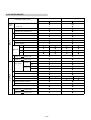
CONTENTS
1. TEST RUN
1-1 TEST RUN METHOD.................................................................................................. 01-01
1-1-1 PROCEDURE...................................................................................................... 01-01
1-1-2 TEST RUN FROM REMOTE CONTROLLER...................................................... 01-02
1-1-3 TEST RUN CONTROL......................................................................................... 01-02
2. FUNCTION OF PRINTED CIRCUIT BOARD
2-1 ELECTRIC CONTROL BLOCK DIAGRAM...............................................................
2-2 PCB LAYOUTS..........................................................................................................
2-2-1 INTDOOR UNIT..................................................................................................
2-2-2 OUTDOOR UNIT................................................................................................
2-2-3 REMOTE CONTROLLER...................................................................................
2-3 ELECTRIC CONTROL FUNCTION TABLE..............................................................
2-3-1 INDOOR UNIT....................................................................................................
2-3-2 OUTDOOR UNIT................................................................................................
2-4 FUNCTION AND SETTING OF EACH SWITCH.......................................................
2-4-1 INDOOR UNIT....................................................................................................
2-4-2 OUTDOOR UNIT................................................................................................
2-4-3 REMOTE CONTROLLER...................................................................................
02-01
02-02
02-02
02-03
02-04
02-05
02-05
02-06
02-07
02-07
02-08
02-09
3. OUTDOOR UNIT OPERATION CONTROL
3-1 OUTDOOR FAN SPEED CONTROL FUNCTION OPERATION...............................
3-2 ELECTRONIC EXPANSION VALVE CONTROL......................................................
3-3 4-WAY VALVE DELAY SWITCHING FUNCTION (REVERSE CYCLE)...................
3-4 BASE HEATER FUNCTION (OPTION).....................................................................
3-5 DE-ICING OPERATION.............................................................................................
3-6 BELT HEATER..........................................................................................................
3-7 DEFROSTING (REVERSE CYCLE)..........................................................................
3-7-1 DEFROSTING OPERATION..............................................................................
3-7-2 DEFROSTING FLOW-CHART...........................................................................
3-8 PROTECTION FUNCTION........................................................................................
3-8-1 COMPRESSOR PROTECTION FUNCTION......................................................
3-8-2 PRESSURE SWITCH PROTECTION.................................................................
3-8-3 DISCHARGE TEMPERATURE PROTECTION..................................................
03-01
03-01
03-01
03-02
03-02
03-02
03-02
03-02
03-03
03-04
03-04
03-04
03-04
CONTENTS
4. INDOOR UNIT OPERATION CONTROL
4-1 FAN CONTROL.........................................................................................................
4-1-1 FAN SPEED SETTING.......................................................................................
4-1-2 "AUTO" POSITION.............................................................................................
4-2 MASTER CONTROL.................................................................................................
4-2-1 "AUTO" POSITION.............................................................................................
4-2-2 "COOL" POSITION.............................................................................................
4-2-3 "HEAT" POSITION..............................................................................................
4-2-4 "FAN" POSITION................................................................................................
4-3 LOUVER CONTROL..................................................................................................
4-3-1 ADJUSTING THE DIRECTION OF AIR CIRCULATION.....................................
4-3-2 SWING OPERATION..........................................................................................
4-4 DRAIN PUMP OPERATION......................................................................................
4-5 FUNCTION.................................................................................................................
4-5-1 AUTO RE-START................................................................................................
4-5-2 INDOOR HEAT EXCHANGER DE-ICING FUNCTION.......................................
4-5-3 SET TEMPERATURE COMPENSATION THE OPERATION START................
4-5-4 COLD AIR DISCHARGE PREVENTION FUNCTION.........................................
4-5-5 ENERGY SAVE FUNCTION...............................................................................
4-6 TIMER CONTROL......................................................................................................
4-6-1 ON / OFF TIMER.................................................................................................
4-6-2 WEEKLY TIMER.................................................................................................
4-7 SETTING THE ROOM TEMPERATURE DETECTION LOCATION..........................
04-01
04-01
04-01
04-02
04-02
04-04
04-05
04-05
04-06
04-06
04-07
04-09
04-09
04-09
04-09
04-09
04-10
04-10
04-11
04-11
04-11
04-12
5. TROUBLE SHOOTING
5-1
5-2
5-3
5-4
5-5
5-6
INDOOR UNIT...........................................................................................................
OUTDOOR UNIT.......................................................................................................
REMOTE CONTROL UNIT.......................................................................................
WORKING INSPECTION..........................................................................................
SYMPTOMS AND CHECK ITEMS............................................................................
NORMAL OPERATION DISPLAY............................................................................
05-01
05-02
05-03
05-04
05-04
05-05
6. INSTALLATION
6-1 PRECAUTIONS FOR INSTALLATION.....................................................................
6-2 ADDITIONAL CHARGE CALCULATION.................................................................
6-3 ELECTRICAL WIRING SETTING.............................................................................
6-3-1 SIMULTANEOUS OPERATION.........................................................................
6-3-2 INDIVIDUAL OPERATION.................................................................................
6-4 ADDRESS SETTING.................................................................................................
6-5 PUMP DOWN METHOD............................................................................................
06-01
06-06
06-07
06-07
06-08
06-09
06-10
CONTENTS
7. REFRIGERANT CAUTION
7-1
7-2
7-3
7-4
7-5
7-6
WHAT IS CFC / HCFC / ?........................................................................................... 07-01
CHARACTERISTICS OF R22 AND R407C............................................................... 07-01
DIFFERENCE FROM CONVENTIONAL MODEL (R22) AND PRECAUTIONS........ 07-02
TOOLS........................................................................................................................ 07-03
PRECAUTIONS FOR INSTALLATION...................................................................... 07-04
PRECAUTIONS FOR DERVICING............................................................................ 07-04
8. APPENDING DATA
8-1 REFRIGERANT PIPE DIAGRAM..............................................................................
8-1-1 SIMULTANEOUS OPERATION.........................................................................
8-1-2 INDIVIDUAL OPERATION..................................................................................
8-2 CHARACTERISTICS OF SENSORS........................................................................
8-3 WIRING DIAGRAM....................................................................................................
8-3-1 OUTDOOR UNIT................................................................................................
8-3-2 INDOOR UNIT....................................................................................................
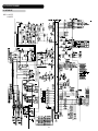
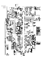
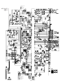
8-4 PCB CIRCUIT DIAGRAM..........................................................................................
8-4-1 OUTDOOR UNIT................................................................................................
8-4-2 INDOOR UNIT....................................................................................................
8-5 MODEL DESIGNATION............................................................................................
08-01
08-01
08-02
08-03
08-04
08-04
08-08
08-14
08-14
08-16
08-22
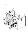
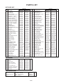
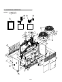
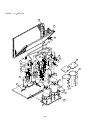
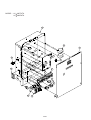
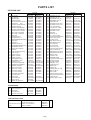
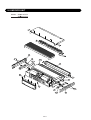
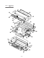
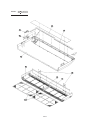
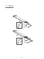
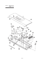
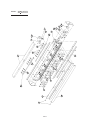
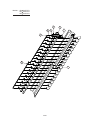
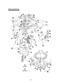
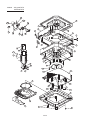
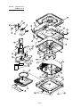
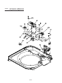
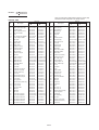
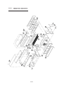
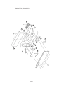
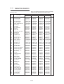
9. DISASSEMBLY ILLUSTRATION & PARTS LIST
9-1 OUTDOOR UNIT........................................................................................................ 09-01
9-2 INDOOR UNIT............................................................................................................ 09-11
1. TEST RUN
1. TEST RUN
1-1 TEST RUN METHOD
1-1-1 PROCEDURE
Turn Power On
Check item
Procedure
1. Turn power on
Outdoor unit
Supply power to the crankcase heater for 12 hours prior to
the start of operation if the outdoor temperature is lower than 21°C
There are not instrument anomalies.
Indoor unit
There are not instrument anomalies.
Blinking Operation indicator and Timer indicator alternately.
The middle of the screen displays time.(Wired Remote Controller)
check
field
Operation Check
Check item
Procedure
1. Operate all of
the indoor units
2. Operate
the outdoor unit
3. Remote controller
Abnormal noise
and abnormal vibration
Water drain
Check intake
and exhaust air temperatures
Compressor operation
There are no abnormal noise or abnormal vibration.
Check the indoor units for water leaks.
Drain the water without accumulating.
Intake - exhaust air temperature differential is 10°C and over (Cooling),
15°C and over. (Heating).
The compressor operates. (Check by noise of operation.)
Run the indoor units one at a time,
and make sure that the corresponding outdoor units also run.
Fan rotation
Abnormal noise
and abnormal vibration
Check high pressure
and low pressure
Check discharge pipe temperature
Check suction pipe temperature
Check heat exchanger temperature
Check the operation in each fan mode.
Operate the remote controller
Operation by remote control can be performed by each remote controller.
There are no abnormal noise or abnormal vibration.
Cooling : low pressure 0.3 - 0.5 Mpa (approx.)
Heating : high pressure 1.6 - 2.2 Mpa (approx.)
Below 125°C
01-01
check
field
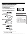
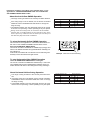
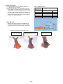
1-1-2 TEST RUN FROM REMOTE CONTROLLER
UTB -YUB / GUB
Standard wired remote controller
Stop the indoor unit. Push the FAN CONTROL button and
MASTER CONTROL button simultaneously for more than two seconds.
The air conditioner will start to conduct a test run and " " will display on
the remote controller display.
However, the SET TEMP./DAY setting button does not have function,
but all other buttons, displays, and protection functions will operate.
Perform the test operation for 60 minutes.
DAY
CLOCK ADJUST
To stop test run, push the START/STOP button of the standard wired remote
controller.
For the operation method, refer to the operating manual and perform operation
check.
Check that there are no abnormal sounds or vibration sounds during test run
operation.
SET BACK
DELETE
DAY OFF
ENERGY
SAVE
SET
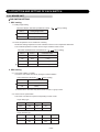
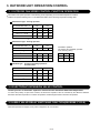
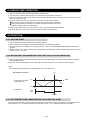
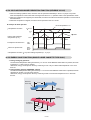
1-1-3 TEST RUN CONTROL
When the test run signal is transmitted from standard wired controller.
(1) The test run operation starts all of the indoor unit connected remote controller and the compressor and fan is
controlled to a maximum flow, regardless of the temperature condition.
(2) De-frosting and frost prevention operation has priority over item(1).
(3) After 60 minutes passes, the test run stops.
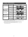
Test running initialization is shown below.
Operating Mode
Cooling
Heating
Fan speed
Hi
Hi
Room Temperature Indication
18
30
Vertical Air Direction Panel
Position 1
Position 4
Horizontal Air Direction Panel
Position 3
Position 3
Swing
OFF
OFF
Please refer to '4-3 LOUVER CONTROL' in this manual and find the definition
for air direction panel position.
01-02
THERMO
SENSOR
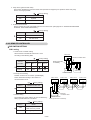
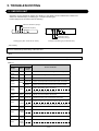
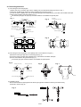
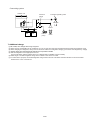
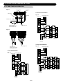
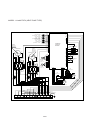
2. FUNCTION OF PRINTED CIRCUIT BOARD
02-01
3
2
1
Power supply
(3) Float switch
(2) Pipe thermistor
(4)
Remote controller signal (5)
(11)
1
2
3
3
2
1
3
2
1
O
F
F
O
F
F
3
2
1
3
2
1
Control Circuit Board
Compressor x 2
(Crankcase heater)
3
2
1
(9) Drain pump
Louver step motor
(8) Vertical (UP/DOWN)
Horizontal(RIGHT/LEFT)
(7) Indoor fan motor
3
2
1
1 2 3
Control Circuit Board
(6) Indicator display
3
2
1
INDOOR UNIT No. 1
(EX : Slave unit)
(20) Electronic expansion valve
(19) 4-way valve
(18)
Outdoor fan motor x 2
(17) (Left fan & Right fan)
INDOOR UNIT No. 0
(EX : Master unit)
Control Circuit Board
(1) Room thermistor
(10)
(16)
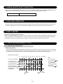
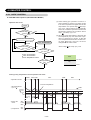
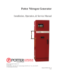
(3),(6),(8),(9),(19)is different on the model.
DIP-SW1
GND
Signal
+B(12V)
UTB-YUB
REMOTE CONTROL UNIT
Communication of signal
AC POWER SUPPLY INPUT
380V- 415V 3
50Hz
(15) Pressure switch control
(14) Outdoor temp. thermistor
6 LED Display No.1~ No.6
(13) Condenser temp. thermistor
1
2
3
4
OUTDOOR UNIT
O
F
F
(12) Discharge temp. thermistor
to others
Indoor unit
Remote control
unit terminal
to others
Indoor unit
power supply
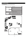
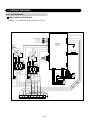
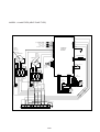
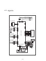
2. FUNCTION OF PRINTED CIRCUIT BOARD
2-1 ELECTRIC CONTROL BLOCK DIAGRAM
0
※
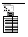
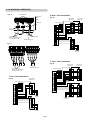
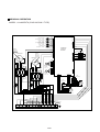
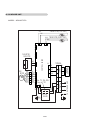
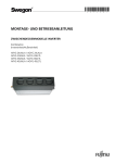
2-2 PCB LAYOUTS
2-2-1 INDOOR UNIT
Indoor unit
SW 1
DIP SW
SW 4
Rotary SW
Jumper
wire
1
Ceiling height setting
2
Room temp correct coefficient of heating 1
3
Room temp correct coefficient of heating 2
1
Auto restart validity / invalidity
2
Indoor unit fan speed switch 1
3
Indoor unit fan speed switch 2
SW 2
Select No. of indoor unit
JM 1
Forbidden
JM 2
Room temp correct coefficient of cooling
JM 3
De-icing prevent temp
CN8
CN15
CN17
(BLACK)
(RED)
(BLACK)
3
2
1
3
0
CN13
W1 SW1
W2
W3
W4
SW4
SW2
(WHITE)
(BLUE)
W9
CN2
(WHITE)
CN18
W8
(BLACK)
W10
CN1
(WHITE)
W6
W5
W7
CN19
(WHITE)
CN6
CN5
CN4
CN9
CN14
CN3
(RED)
(WHITE)
CN16
CN10
JM1
JM2
JM3
(BLACK)
O
F
F
O
F
F
1
11
CN
)
D
(RE
2
CN7
E101
(GREEN)
SW3
CN12
W103
(WHITE)
W102
(WHITE)
W104
(BLACK)
02-02
F101
W101
(3150mA) (BLACK)
T 3.15A 250V
(BLUE)
(BLACK)
(GREEN)
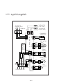
F1
CN7 (BLACK)
Outdoor fan-low sound
(YELLOW)
E
4
4
1
(RED)
EV.B
CN20
(PINK)
W2
(RED)
W1
Pump down
(WHITE)
(BLUE)
CN8 FLASH
3
EV.B
CN21
LED6
LED3
Defrost temperature selected
HEATER.A
CN6
LED5
LED2
(RED)
CN19 P.SW-B
(BLUE)
CN9 TH
2
4WV.B
CN5
LED4
LED1
(WHITE)
CN13 P.SW-A
(RED)
(RED)
(WHITE)
CN18 COMP.B
(WHITE)
CN12 EEV.B
CN10 COMP.A
CN11 EEV.A
Forced defrost
4WV.A
CN4
(RED)
SW1
3
CN22
MAIN RELAY.A
2
O
F
F
CN14 TEST
(BLUE)
(WHITE)
(YELLOW)
CN3 FANMOTOR-1
CN2 FANCAPA-1
CN16 FANMOTOR-2
CN15 FANCAPA-2
02-03
(RED)
SW 1
(YELLOW)
(WHITE)
DIP SW
1
T 6.3A 250V (6300mA)
AC IN
CN23
MAIN RELAY.B
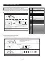
2-2-2 OUTDOOR UNIT
Outdoor unit
2-2-3 REMOTE CONTROLLER
Remote controller
DIP SW
1
2
Dual remote controller setting
3
Group control setting
4
Model setting
5
6
Auto changeover setting
Memory backup setting
SWITCH POSITION
Wired remote controller
Front case (back side)
OFF
ON
1
2
3
4
5
6
DIP Switch
02-04
2-3 ELECTRIC CONTROL FUNCTION TABLE
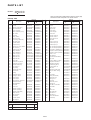
2-3-1 INDOOR UNIT
INDOOR UNIT TYPE
Ceiling
45
MODEL CODE
36
: Simultaneous
30
: Individual
25
24
18
(1) Room Thermistor (Sensor)
(2) Pipe Thermistor (Sensor)
(3) Float Switch Control
Thermal Fuse (Within Terminal board)
INPUT
No. 1 High Ceiling mode
1
DIP SW1 No. 2 Compensation Heating 1
No. 3 Compensation Heating 2
2
DIP SW4
3
Jumper
4
Rotary SW
No. 1 Auto restart
No. 2 Indoor Fan Table 1
No. 3 Indoor Fan Table 2
JM 1 Remote controller type
JM 2 Compensation Cooling
JM 3 De-icing Prevent temp.
Select No. of indoor unit
(4) Signal Transmitter-Receiver Signal
(Outdoor unit
Indoor unit )
OUTPUT
(5) Remote controller signal
(Remote control
Indoor unit )
(6) Indicator
Display LED
• Operation
• Timer
• Swing (UP/DOWN)
• Swing (RIGHT/LEFT)
(7) Indoor Fan
Motor Speed
• High
• Med
• Low
(8) Louver Motor
Vertical (UP/DOWN)
Horizontal (RIGHT/LEFT)
(9) Drain Pump
(10) Signal Transmitter-Forward Signal
(Indoor unit
Outdoor unit)
(11) Remote controller signal
(Indoor unit
Remote Control)
02-05
Universal
Floor / Ceiling
Cassette
(compact)
Cassette
Duct
(Standard Static
Pressure)
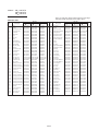
2-3-2 OUTDOOR UNIT
Simultaneous Type
OUTDOOR UNIT TYPE
MODEL
CODE
Cooling only
90
90 (45 x 2)
(12) Discharge Temp. Thermistor A
(11) Discharge Temp. Thermistor B
(13) Condensor Temp. Thermistor A
(11) Condensor Temp. Thermistor B
INPUT
(14) Outdoor Temp. Thermistor
(15) Pressure Switch A
(11) Pressure Switch B
No.1 Defrost temp. Selected
5 DIP SW
No.2 Forced Defrost
No.3 Pump down
No.4 Outdoor Fan-low sound
(10) Serial Transmitter-Forward Signal A
(Indoor unit
Outdoor unit)
Serial Transmitter-Forward Signal B
(Indoor unit
Outdoor unit)
(17) Outdoor Fan
Motor Speed
Fan motor 1
Fan motor 2
High
Low
High
Low
OUTPUT
(18) Compressor A
(11) Compressor B
(19) 4-Way Valve A
(11) 4-Way Valve B
(20) Electronic Expansion Valve A
(11) Electronic Expansion Valve B
LED Display No. 1 ~ No. 6
(4) Remote Transmitter-Receiver Signal A
(Indoor unit
Outdoor unit)
Remote Transmitter-Receiver Signal B
(Indoor unit
Outdoor unit)
02-06
Heat pump
Individual Type
Cooling only
Heat pump
2-4 FUNCTION AND SETTING OF EACH SWITCH
2-4-1 INDOOR UNIT
DIP SWITCH SETTING
1. SW1 setting
1-1 Ceiling height setting
CEILING HEIGHT SETTING (CASSETTE TYPE) (
SW1-1
Ceiling height mode
OFF
Standard
ON
High ceiling
Factory setting)
This function is validity only large cassette type
1-2 Room temperature correct coefficient of heating
Decide the heating temperature correct coefficient value for room temperature thermistor.
The overall temperature increases when a larger coefficient value is used.
HEATING TEMPERATURE CORRECTION (
Factory setting)
SW1-2
SW1-3
Coefficient value
OFF
OFF
+ 2 deg
ON
OFF
- 2 deg
OFF
ON
0 deg
ON
ON
+ 4 deg
2. SW4 setting
2-1 Auto restart validity / invalidity
Control the auto restart function by turning this switch ON/OFF.
AUTO RESTART SETTING (
SW4-1
Auto restart
OFF
Invalidity
ON
Validity
Factory setting)
* Please set it in the same way when remote control is a group control.
2-2 Indoor unit fan speed switch
This switch can select fan speed corresponding to each model.
Large ceiling type
AB30
AB36
AB45
SW4-2
OFF
ON
OFF
SW4-3
OFF
OFF
ON
AU25
AU30
AU36
AU45
SW4-2
ON
OFF
ON
OFF
SW4-3
ON
ON
OFF
OFF
Large cassette type
02-07
JUMPER WIRE SETTING
(
JP
Function
Connect
Factory setting)
Disconnect
JM1
Forbidden
Type with sensor
JM2
Room temperature correct
coefficient of cooling
0°C
+2°C
JM3
indoor heat exchange icing, the
de-icing operation temperature.
Set-up 2°C - Reset 6°C
Set-up 4°C - Reset 8°C
ROTARY SW SETTING
SW2 Setting
Sets the unit number of the indoor unit to MASTER or SLAVE.
Master setting
Other Slave setting
0
1
2
Slave
Master
Indoor unit A
Slave
Indoor unit B
Indoor unit C
3
Slave
Indoor unit D
2-4-2 OUTDOOR UNIT
DIP SWITCH SETTING
SW1 setting
1. Forced defrost
This function first melts the outdoor heat exchange ice and inspects the pressure and temperature when
servicing and maintaining the outdoor unit at heating operation.
(
SW1-1
Factory setting)
Forced defrost
OFF
ON
Defrost start
2. Defrost temperature selected
The Defrost start operation temperature can be changed according to the outside air temperature region
environment.
(
SW1-2
Factory setting)
Defrost temperature selected
OFF
-10°C
ON
-7°C
02-08
3. Pump down (pressure SW mode)
This function disables the pressure switch when operation is stopped by low pressure switch and pump
down is not longer possible.
(
Factory setting)
SW1-3
Pump down
OFF
Operate
ON
Release
4. Outdoor fan-low sound
Set the outdoor fan noise value [2dB (A)] to the low-noise mode. (See page 03-01 "OUTDOOR FAN SPEED
CONTROL FUNCTION OPERATION".)
(
Factory setting)
SW1-4
Outdoor fan-low sound
OFF
Standard
ON
Fan-low sound
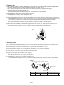
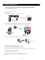
2-4-3 REMOTE CONTROLLER
DIP SWITCH SETTING
SW1 setting
1-1 Dual remote controller setting
Set the remote controller DIP switch No.1 and 2
according to the following table.
(
Number of
remote
controller
SW1-1
SW1-2
1 (Normal)
ON
OFF
2 (Dual)
OFF
OFF
Indoor unit
Factory setting)
Master unit
Slave unit
SW1-1
SW1-2
ON
ON
1 2 3
When ground wire
is necessary
Number of indoor unit connection (One/Multiple)
This is switched according to the number of
connected indoor units.
Indoor unit 0
1 2 3
Factory setting)
SW1-3
Number of indoor unit
OFF
One unit connection
ON
Multiple unit connection
1 2 3
1-3 Model setting
The system type of the outdoor unit can be selected by
setting up DIP switch No.4 as follows.
(
SW1-4
1 2 3
1 2 3
Master unit
Slave unit
Remote controller
1-2 Group control setting
(
Remote controller cable
Factory setting)
Model
OFF
Heat Pump model or
Heat Recovery model
ON
Cooling only model
02-09
Indoor unit 1
1 2 3
Remote
controller cable
Remote controller
When ground wire is necessary
Indoor unit 2
1 2 3
Indoor unit 3
1 2 3
1-4 Auto changeover setting
Selecting auto changeover validity / invalidity.
(
SW1-5
Factory setting)
Auto changeover
OFF
Invalidity
ON
Validity
1-5 Memory backup setting
Set to ON to use batteries for thr memory backup.
If batteries are not used, all of the settings stored in memory will be deleted if there is a power failure.
(
SW1-6
Factory setting)
Memory backup
OFF
Invalidity
ON
Validity
02-10
3. OUTDOOR UNIT OPERATION CONTROL
3. OUTDOOR UNIT OPERATION CONTROL
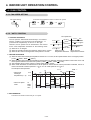
3-1 OUTDOOR FAN SPEED CONTROL FUNCTION OPERATION
The Outdoor Fan speed operates in the following mode, depending on the outside temperature condition.
Outdoor Fan speed switching has a ±1 C differential relative to the following temperature setting table.
Simultaneous type : Cooling operation
OUTDOOR DIP SW 1- 4
ON
OFF
Outdoor Fan motor
Right
Left
Right
Left
T > 25 C
Hi
Hi
Hi
STOP
> T > 10 C
25 C =
>T
10 C =
Lo
Lo
Lo
Lo
Lo
STOP
Lo
STOP
T C : Outdoor Temperature thermistor
Simultaneous type : Heating operation
OUTDOOR DIP SW 1- 4
Outdoor Fan motor
OFF
Right
T > 16 C
ON
Left
Right
Left
Intermittent operation
> T > 11 C
16 C =
>T>9 C
11 C =
Lo
STOP
Lo
STOP
Lo
Lo
Lo
Lo
>T
9 C=
Hi
Hi
Hi
STOP
Intermittent operation:
The outdoor fan repeatedly operates
at the following timing:
Time
Right
Left
2 min. STOP STOP
10 sec.
Lo
Lo
Individual type : Cooling and heating operations
: Common mode
OUTDOOR DIP SW 1- 4
OFF
ON
Outdoor Fan motor
Right
Left
Right
Left
T > 26 C
Hi
Hi
Hi
STOP
> T > 10 C
26 C =
>T
10 C =
Lo
Lo
Lo
Lo
Hi
Hi
Hi
STOP
3-2 ELECTRONIC EXPANSION VALVE CONTROL
Control process of electronic expansion valve and each thermistor detection temperature
To control the quantity of super heat constant, the electronic expansion valve is controlled by the difference between
thermistor detection temperature of outdoor temperature and discharge thermistor detection temperature.
3-3 4-WAY VALVE DELAY SWITCHING FUNCTION(REVERSE CYCLE)
When heat operation is stopped, 4-way valve is stopped 2 min. 35 sec later.
03-01
3-4 BASE HEATER FUNCTION(OPTION)
When the outdoor temperature is minus, turn ON to warm the outdoor unit drain pan and positively discharge the drain
water when the outdoor temperature thermistor is 2 C or lower and the operating mode is HEAT.
CN6 OUT-PUT
MAXIMUM HEATER OUTPUT 100W
(CN6 FOR OUTDOOR UNIT PRINTED CIRCUIT BOARD)
3-5 DE-ICING OPERATION
To prevent outdoor heat exchanger icing at heating operation heating overload, after the compressor and outdoor fan
have been operated for two hours, the compressor is stopped for 3 minutes and the outdoor fan is de-iced at Hi.
3-6 BELT HEATER
Belt heater is installed around the compressor.
When the outdoor temperature is less than 21 C, oil is fallen in the compressor and the refrigerant is melted into oil and
oil may be diluted, then the bearing metal etc. of the compressor motor is easy to damage when starting the compressor.
To prevent the above, the crank case heater is installed. The heater operates under the compressor halt.
3-7 DEFROSTING(REVERSE CYCLE)
3-7-1 DEFROSTING OPERATION
1. Defrosting operation
When the outdoor piping thermistor detection temperature is -7 C (DIP SW : ON) or less (-12 C or less for 10 minutes
after switching from one room operation to two rooms operation, and -7 C after 10 minutes and in one room operation) after timer of 6 minutes timer or 10 minutes timer, besides 40 minutes timer are up, defrosting starts.
Defrosting start condition
0
Comp. A1 (ON/OFF)
10 20 30 40 50 60 70 80 90 100 (Min.)
30
ON
OFF
10
ST : Timer Start
(Comp. A OFF
ST TU RS ST RS
6 minutes timer
(Comp. OFF is less than 20 min.) ST TU RS 0 6
10 minutes timer
(Comp. OFF is more than 20 min.) ST 10
(20)
(15)
40 minutes timer
(Comp. total operation time)
Outdoor pipe : - 8 C
thermistor
Operation
start
0
(5)
6
TU
03-02
RS
40
Defrost
start
[Note]
END
ON)
TU : Timer UP
6,10,40 after the
setting time passed
RS : Reset
(Comp. A ON
OFF
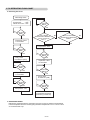
3-7-2 DEFROSTING FLOW-CHART
2. Defrosting flow-chart
Defrosting starts
Compressor
: OFF
Indoor fan motor : OFF
No
3 seconds
Mask
Yes
Expansion valve
is controlled
1 minute
Mask
No
Yes
Is the piping
thermistor detection
temp. more than
10°C ?
No
Have 15 minutes
passed since defrosting
starts ?
Yes
Compressor : OFF
No
25 seconds
Mask
Yes
4-way valve
is switched. (OFF)
No
3 seconds
Mask
Yes
Expansion valve
is controlled
No
3 seconds
Mask
Yes
Compressor : ON
No
3 seconds
Mask
Yes
Expansion valve
is controlled
No
25 seconds
Mask
Yes
4-way valve
is switched. (ON)
No
3 seconds
Mask
Yes
After this the unit follows
conventional operation.
(Defrosting is finished)
3. DEFROSTING FINISH
Defrosting is performed after the compressor is turned on and one minute mask is finished.
It will be completed when the outdoor piping thermistor temperature is 10°C or more or time
of 15 minutes timer is up.
03-03
No
3-8 PROTECTION FUNCTION
3-8-1 COMPRESSOR PROTECTION FUNCTION
1. THREE MINUTES DELAY FUNCTION (3ST)
The outdoor unit does not operate for three minutes
after the power switch is turned on. (Compressor protection, breaker off prevention, etc.)
2. THREE MINUTES CONTINUOUS FUNCTION (3HT)
The unit continues to run for three minutes after the compressor starts.
Compressor ON/OFF control
3HT
3ST
ON
OFF
ON
OFF
Note:
When test operation is performed during continuous heating operation, it takes some time until air blows out from the
indoor unit because "Three minutes delay" and "Cold air discharge prevention" have priority over TEST operation.
3-8-2 PRESSURE SWITCH PROTECTION
To prevent the refrigerant liquid from returning to the compressor during cooling operation, the following operations are
performed.
Pressure SW
ON
OFF
Pressure value (kgf/cm )
Up to 2
3 or more
Function operation
Compressor stop
Normal operation
(Reset)
2
3-8-3 DISCHARGE TEMPERATURE PROTECTION
The following operations are performed for compressor body heating protection
Discharge temperature
125 C
95 C
Function operation
Compressor stop
Normal operation
(Reset)
03-04
4. INDOOR UNIT OPERATION CONTROL
4. INDOOR UNIT OPERATION CONTROL
4-1 FAN CONTROL
4-1-1 FAN SPEED SETTING
Fan speed setting
Press the FAN CONTROL button to set the fan speed.
AUTO
HIGH
MED
LOW
4-1-2 "AUTO" POSITION
Fan speed zone
1. COOLING OPERATION
The fan speed is determined automatically in accordance
with the condition "(TR(corrected room temperature) - TS
(corrected set temperature)" as shown on the right.
However, the fan speed zone is determined in the manner
as the room temperature increases for the following cases.
TR-TS
1°C
Hi zone
2°C
TR-TS
2°C
Med zone
Low zone
TR-TS 1°C
(1) When the TS is changed.
(2) When the operation mode is changed from other mode to "COOL".
When the room
(3) When the fan control is changed from other position to "AUTO".
temperature decreases
TR-TS
2°C
TR-TS
3°C
TR-TS
3°C
2°C
When the room
temperature increases
2. HEATING OPERATION
(1) When the indoor heat exchanger temperature reaches 47°C or more, the fan speed switches to the next higher position.
("LOW"
"MED", "MED"
"HIGH").
(2) When the indoor heat exchanger temperature drops below 41°C while the refrigerant circulation of the indoor unit is ON,
the fan speed switches to the next lower position ("HIGH"
"MED", "MED"
"LOW").
(3) After switching the fan speed, it does not switch again within 2 minutes.
(4) When "FAN CONTROL" is switched from a set fan speed to "AUTO" after the cold air prevention is released , the fan of
indoor unit will start at "MED" speed for THE
41°C or at "LOW" speed for THE 41°C.
An example for heat operation
TIME -->
THE °C
(1)
• Indoor heat
exchanger
temperature (THE °C)
47°C
(2)
41°C
(3)
• Indoor fan speed
mode
HI
MED
LOW
OFF
2min.
4. FAN OPERATION
The indoor fan rotates continuously at "Lo" speed.
04-01
2min.
2min.
2min.
2min.
4-2 MASTER CONTROL
4-2-1 "AUTO" POSITION
A: COOLING & DRY operation (COOLING ONLY MODEL)
(1) When starting yhe operation at "AUTO" or
when switched to "AUTO" from other modes,
if the room temperature is higher than the set
temperature +2°C (Room temp. Set temp.
(Ts) +2°C), "COOL"mode is set automatically
and an air conditioner operates until the room
temperature reaches the condition "Room
temp. Set temp. (Ts) +1°C".
Operation flow chart
START
NO
Room temp.
Ts+2°C ?
(2) When the room temperature is less than the
set temperature (Ts) +2°C at the start of operation or changing into "AUTO", or after the
room temperature reaches the condition "Room temp. Set temp. (Ts)+2°C", the unit is
changed into the "DRY" mode.
Yes
COOLING OPERATION
Room temp.
control
Yes
Room temp.
Ts+ 1°C ?
DRY OPERATION
"Room Temp.
NO
Yes
3-min. ST Protection
3-min. HT Protection
Room temperature control
Set Temp. (Ts) +2°C
Room temp.
Ts+ 2°C ?
NO
Cool
Ts +2°C
NO
Compressor
off ?
Dry
Yes
Ts°C
Cooling or Dry temperature control operation time chart
Operation mode
COOL
DRY COOL
TIME
3HT
Compressor
DRY
TR Room temperature
Set temperature
(Ts = T )
T +2°C
T +1°C
0.5°C
T
Indoor fan
motor
COOL
DRY
2min 2min
3ST
SET
LOW
OFF
ON
OFF
04-02
3HT
3ST
3HT
3ST
3HT
B: AUTO CHANGEOVER operation [REVERSE CYCLE]
When AUTO CHANGEOVER operation is selected, the air conditioner selects the appropriate operation mode
(Cooling or Heating) in response to your room's temperature.
When AUTO CHANGEOVER operation first selected, the fan will operate at very LOW speed for about one minute,
during which time the unit detects the room conditions and selects the proper operating mode.
(1) Monitoring (Room temperature detection)
The monitoring is that the indoor fan motor rotates intermittently (0.5 sec ON at Low / 2.0 sec OFF) for 60 seconds to
detect the room temperature (Tr) after the unit starts with
the MASTER CONTROL of AUTO.
In case that the 3-min delay function actuates or is actuating the monitoring continues until the 3-min delay function
is expired and furthermore 30 seconds elapses.
Auto changeover flow chart
START
(1) Monitoring (one minute timer)
Tsa
(3)
Ts
During the monitoring :
Indoor fan motor
Outdoor fan motor Hi
Outdoor fan motor Lo
4-way valve
Conpressor
(2)
Tr
NO
(Tsa-2)°C
Tr
Yes
(Tsa+2)°C
Heating
Yes
Cooling
Tsa=Ts+CC
4-way valve is turned on
The compressor is turned on.
Thermostat control
3 min. SH
3 min. ST
De-icing function
Cold air prevention
Overload protection
Defrost operation
Is the
compressor turned
off ?
NO
: OFF
(2) Auto operation
The cooling operation starts when the monitoring is
expired and then the detected room temperature (Tr) is
given in the formula [Tr (Tsa+2)°C].
The heating operation starts when the monitoring is
expired and then the detected room temperature (Tr) is
given in the formula [Tr (Tsa-2)°C].
The monitoring continues when the detected room temperature (Tr) is given un the following formula.
[(Tsa-2)°C Tr (Tsa+2)°C]
The cooling or heating operation is performed in accordance with the microcomputer functions such as thermostat control, 3-min delay function, etc.
When the compressor continues to be in the OFF state for
6 minutes by the thermostat control in either of the cooling
or heating, it is switched to the monitoring.
Room temperature (TR) control zone
NO
Cool
Monitoring
Yes
Does the compressor continue to be
turned off more than 6
minutes ?
Yes
: S-Lo
: OFF
: OFF
Heating
Tsa+2°C
Tsa°C
Tsa-2°C
NO
4-way valve is turned off.
(3) Tsa : Set temperature in AUTO operation
During cooling operation or after switching to monitoring from cooling operation, Tsa is identical to the temperature (Ts)
selected out of the THERMOSTAT.
04-03
During heating operation or after switching to monitoring from heating operation, “Tsa” is a value which the heating correction coefficient (CC) is added to the temperature (Ts) select out of the THERMOSTAT.
(Tsa=Ts+CC)
[Heating correction coefficient (CC) : See page 02-07]
When the set temperature of the THERMOSTAT (Ts) is changed, the last temperature has priority over the former set
temperature.
Even though the set temperature is changed to switch from cooling to heating or from heating to cooling, such a switching is carried out after the compressor continues to be in the OFF state for 6 minutes by the thermostat control.
An example for AUTO CHANGEOVER TEMPERATURE CONTROL time chart
Operation mode
(Moni.: Monitoring)
Moni.
Cool
Moni.
Cool
Set temperature
Moni.
Heat
Moni.
Heat
TR Room temperature
Ts+2°C
TIME
0.5°C
Ts
Ts–2°C
1min. 3HT
3ST
3ST
3ST
3HT
3ST
3HT
Comp. OFF 6min.
Indoor fan
• motor
SET
S-LOW
OFF
Compressor & ON
OFF
Outdoor fan
4-Way valve
ON
OFF
4-2-2 "COOL" POSITION
1. When using the cooling mode, set the temperature to a value lower than the current room temperature.
2. If it is set higher than the current room temperature the unit will not enter the cooling mode and only the fan will operate.
An example for COOLING TEMPERATURE CONTROL time chart (Manual setting)
Set temperature (Ts=T Correction)
(b)
(C)
Less than 6 min.
3~6 min.
TR
(a)
T +0.5°C
TIME
T °C
Compressor
ON
OFF
3ST
3HT
3HT
3HT
3HT
(b)
Indoor fan
ON
OFF
(a) Compressor turned OFF :TR
(b) Compressor turned ON :TR
(c) Compressor turned ON :TR
T
T +0.5°C (In case of 3 to 6 minutes)
T
(In case that the compressor stops more than 6 minutes)
04-04
4-2-3 "HEAT" POSITION
1. Set the temperature higher than the current room temperature. If it is set to a lower temperature, heating will not
start.
2. For about 3 ~ 5 minutes after the start of heating, the fan will operate very slowly, and then switch to the selected fan
setting. This period allows the indoor unit's heat exchanger to warm-up before emitting warm air.
3. During defrosting, the OPERATION indicator lamp flashes 3 sec. ON and 1 sec. OFF, and the heating operation is
temporarily interrupted.
An example for HEATING TEMPERATURE CONTROL time chart (Manual setting)
(C)
Set temperature (Ts=T Correction)
3~6 min.
(a)
T +0.5°C
Less than 6 min.
TR
(b)
T °C
27°C
Compressor
ON
OFF
Indoor fan
¥speed mode
SET
S-LOW
OFF
3ST
3HT
20sec.
20sec.
3HT
20sec.
20sec.
Cold air prevention
(a) Compressor OFF : TR
(b) Compressor ON : TR
(c) Compressor ON : TR
T +0.5°C
T
T +0.5°C (When the compressor stops after less than 6min.)
4-2-4 "FAN" POSITION
1. In this position, the fan operates alone to circulate air. The room temperature will not be changed.
2. Operates at the air flow set in the FAN CONTROL mode.
3. When only the "FAN" mode is being used, setting to "AUTO" is equivalent to set it at "MED".
04-05
4-3 LOUVER CONTROL
4-3-1 ADJUSTING THE DIRECTION OF AIR CIRCULATION
Instructions relating to heating ( ) are applicable only to "HEAT
PUMP MODEL".
Begin air conditioner operation before performing this procedure.
Vertical Air Direction Adjustment
This instructions are applicable to "CEILING SUSPENSION
TYPE", "FLOOR CONSOLE/UNDER CEILING DUAL TYPE" and
"CASSETTE TYPE".
DAY
CLOCK ADJUST
SET BACK
DELETE
DAY OFF
ENERGY
SAVE
THERMO
SENSOR
SET
Press the VERTICAL AIR FLOW DIRECTION SET button.
Each time the button is pressed, the air direction range will
change as follows:
1
2
3
4
Example : When set to vertical air direction.
The remote controller's display does not change.
DANGER!
Never place fingers or foreign objects inside the
outlet ports could cause personal injury.
CEILING SUSPENSION TYPE
Always use the remote controller's AIR FLOW
DIRECTION button to adjust the UP/DOWN
air direction flaps or RIGHT/LEFT air direction
louvers. Attempting to move them manually
could result in improper operation; in this case,
stop operation and restart. The flaps should begin to operate properly again.
During use of the Cooling mode, do not set
the UP/DOWN air direction flaps in the 4 position for long periods of time, since water vapor
may condense near the outlet port and drops
of water may drip from the air conditioner.
When used in a room with infants, children,
elderly or sick persons, the air direction and
room temperature should be considered carefully
when making settings.
1
2
3
4
FLOOR CONSOLE/UNDER CEILING DUAL TYPE
1
2
3
4
CASSETTE TYPE
4
3
2
1
1
2
3
4
Use the air direction adjustments within the ranges shown above.
The vertical airflow direction is set automatically as shown, in accordance with the type of operation selected.
During Cooling mode : Horizontal flow 1
During Heating mode : Downward flow 4
During AUTO mode operation, for the first minute after beginning operation, airflow will be horizontal 1 ; the air
direction cannot be adjusted during this period.
04-06
Horizontal Air Direction Adjustment
This instructions are applicable to "CEILING SUSPENSION
TYPE" and "FLOOR CONSOLE/UNDER CEILING DUAL TYPE"
Press the HORIZONTAL AIR FLOW DIRECTION SET button.
Each time the button is pressed, the air direction range will
change as follows:
1
2
3
4
DAY
CLOCK ADJUST
SET BACK
DELETE
5
DAY OFF
ENERGY
SAVE
THERMO
SENSOR
SET
The remote controller's display does not change.
CEILING SUSPENSION TYPE
1
2
Example : When set to horizontal air direction.
3
4
5
FLOOR CONSOLE/UNDER CEILING DUAL TYPE
1
2
3
4
5
4-3-2 SWING OPERATION
Instructions relating to "the indoor unit's indicator lamp" ( ) are
applicable to "CEILING SUSPENSION TYPE" and "FLOOR CONSOLE/UNDER CEILING DUAL TYPE".
Begin air conditioner operation before performing this procedure.
To select Vertical airflow SWING Operation
DAY
CLOCK ADJUST
SET BACK
DELETE
DAY OFF
ENERGY
SAVE
THERMO
SENSOR
SET
This instructions are applicable to "CEILING SUSPENSION TYPE",
"FLOOR CONSOLE/UNDER CEILING DUAL TYPE" and "CASSETTE TYPE".
Press the VERTICAL SWING button.
The remote controller's VERTICAL SWING lamp (orange) **and
indoor unit's SWING indicator lamp (VERTICAL SWING) (orange)
will light up.
In this mode, the UP/DOWN air direction flaps will swing automatically to direct the air flow both up and down.
To stop Vertical airflow SWING Operation
Press the VERTICAL SWING button onse again.
The remote controller's VERTICAL SWING lamp **and indoor
unit's SWING indicator lamp (VERTICAL SWING) will go out.
Airflow direction will return to the setting before swing was begun.
04-07
Example : When set to vertical swing.
Instructions relating to "the indoor unit's indicator lamp" (**) are
applicable to "CEILING SUSPENSION TYPE" and "FLOOR CONSOLE/UNDER CEILING DUAL TYPE".
About Vertical Airflow SWING Operation
The range of swing is relative to the currently set airflow direction.
If the swing range is not as desired, use the remote controller's
VERTICAL AIR FLOW DIRECTION SET button to change the
range of swing.
The SWING operation may stop temporarily when the air conditioner's fan is not operating, or when operating at very low speeds.
Range of swing
Air flow direction set
1 to 3
2 to 4
1
2
2 to 4
1 to 4 (All range)
3
4
Air direction range (See page 04-06)
During use of the Cooling mode, do not set the air UP/ DOWN
direction flap, in the 4 position for long periods of time, since
water vapor may condense near the outlet port and drops of
the water may drip from the air conditioner.
To select Horizontal Airflow SWING Operation
This instructions are applicable to "CEILING SUSPENSION TYPE" and "FLOOR CONSOLE/UNDER CEILING DUAL TYPE".
Press the HORIZONTAL SWING button.
The remote controller's HORIZONTAL SWING lamp (orange)**and
indoor unit's SWING indicator lamp (HORIZONTAL SWING) (orange) will light up.
In this mode, the RIGHT/LEFT air direction louvers will swing automatically to direct the airflow both right and left.
DAY
CLOCK ADJUST
SET BACK
DAY OFF
DELETE
ENERGY
SAVE
THERMO
SENSOR
SET
Example : When set to horizontal swing.
To stop Horizontal airflow SWING Operation
Press the HORIZONTAL SWING button once again.
The remote controller's HORIZONTAL SWING lamp **and indoor
unit's SWING indicator lamp (HORIZONTAL SWING) will go out.
Airflow direction will return to the setting before swing was begun.
About Horizontal Airflow Swing Operation
The range of swing is relative to the currently set airflow direction.
If the swing range is not as desired, use the remote controller's
HORIZONTAL AIR FLOW DIRECTION SET button to change
the range of swing.
The SWING operation may stop temporarily when the air conditioner's fan is not operating, or when operating at very low speed.
04-08
Air flow direction set
1
2
3
4
5
Range of swing
1 to 5 (All range)
1 to 3
2 to 4
3 to 5
1 to 5 (All range)
Air direction range (See page 04-07)
4-4 DRAIN PUMP OPERATION
1. When a compressor starts, the drain pump starts simultaneously.
2. The drain pump operates continuously for 3 minutes after the compressor is turned off.
3. When the compressor stops by the "Indoor heat exchanger de-icing function", the drain pump is turned off in 1 hour
after the compressor stops.
4. When the water level in the drain pan rises up and then the float switch functions:
1 Microcomputer stops the compressor and indoor and outdoor fan motor operation.
2 Drain pump operates continuously for 3 minutes after the float switch is turned off.
(Almost condensing water may be drained)
5. When the float switch turns ON continuously for 3 min., "FAILURE INDICATION" operates.
6. When the float switch turns OFF within 3 min., the unit starts cooling operation.
4-5 FUNCTION
4-5-1 AUTO RE-START
1. The air conditioner restarts with the previous setting operation.
2. At the restarting of air conditioner, "THREE MINUTE DELAY FUNCTION" operates.
3. At the restarting of air conditioner for heating operation, "COLD AIR DISCHARGE PREVENTION FUNCTION"
operates.
4. When the power of the timer is interrupted during operation and resets later, the timer display lamp flashes on and off
(turned on 3 sec. / off 1 sec.).
4-5-2 INDOOR HEAT EXCHANGER DE-ICING FUNCTION (COOLING OPERATION)
(1) When the temperature of the heat exchanger at the indoor side drops below 2°C during cooling operation, operation
of the compressor stops.
(2) After that, when the temperature of the indoor heat exchanger rises above 6°C, compressor starts. (Reset)
Note :
The de-icing setting temperature can be selected at JP3 on the control PCB.
An example for Cooling
(2)
(1)
Indoor heat exchanger
¥ temperature (Tn )
6°C
TIME
Tn
2°C
Compressor
ON
OFF
RESET
4-5-3 SET TEMPERATURE COMPENSATION THE OPERATION START
At the start of the operation and when MASTER CONTROL is switched to heating and cooling, the set temperature are
compensated by +2°C for heating operation for 60 minutes and by -1°C for cooling operation for 40 minutes.
04-09
4-5-4 COLD AIR DISCHARGE PREVENTION FUNCTION (REVERSE CYCLE)
1. When the heating operation starts, the indoor unit fan operates intermittently in the S-LO* (Super-Low) mode.
After the temperature of the indoor heat exchanger rises above 27°C, operation enters to the specified flow mode.
2. When the compressor is stopped by the thermostat, the indoor fan starts the intermittent operation in 20 seconds as
described above.
3. While the compressor is stopped, the indoor unit fan operates in the S-LO mode.
An example for Heat operation
Temperature correction
Room temperature TR °C
T +0.5°C
T °C
TIME
Indoor heat exchanger
temperature (Tn °C)
27°C
20sec.
Compressor & outdoor fan
ON
OFF
Indoor fan speed mode
SET
S-LO
OFF
20sec.
* Temperature correction T =Ts (Indoor setting temperature) + Ta (+4)°C
4-5-5 ENERGY SAVE FUNCTION (SINGLE LARGE CASSETTE TYPE ONLY)
1. During cooling/dry operation:
The thermostat temperature setting increases by 1°C as soon as the ENERGY SAVE button is pressed, and then
increases by 1°C after one hour passed.
Afterwards, energy consumption is saved by continuing to cool or dry at a thermostat temperature of 2°C more
than set.
2. During heating operation [REVERSE CYCLE]:
The thermostat temperature setting decreases by 1°C as soon as the ENERGY SAVE button is pressed,and then
decreases by another 1°C every thirty minutes.
Afterwards, energy consumption is saved by continuing to heat at a thermostat temperature of 4°C less than
that set.
ENERGY
SAVE ON
1hour.
2°C
1°C
1°C
ENERGY
SAVE ON
2°C
3°C
30min.
1 hour.
1 hour
30 min.
04-10
Setting
temperature
Setting
temperature
4°C
4-6 TIMER CONTROL
4-6-1 ON / OFF TIMER
Instructions related to heating are applicable to "HEAT PUMP MODELS".
The timer function may not be available because of initial setting.
To set the ON / OFF timer
1
2
Press the TIMER MODE button to
select the ON TIMER or OFF
TIMER.
CLOCK ADJU
MO TU WE TH FR SA
From 1 to 24 hours
ex.OFF timer set for 6 hours
Press the SET TIME buttons to set time.
After the time is set, the timer will start automatically.
The amount of time until the OFF timer operates that is displayed on the timerdisplay decreasesas time passes.
No display
NON
STOP
OFF
TIMER
ON
TIMER
WEEKLY
TIMER
To cancel the timer mode
DELETE
Press the DELETE button to cansel the timer mode.
The timer mode can also be canceled by changing the timer mode using the TIMER MODE botton.
4-6-2 WEEKLY TIMER
Instructions related to heating are applicable to "HEAT PUMP MODELS".
The timer function may not be available because of initial setting.
To set the WEEKLY timer
1
2
SU MO TU WE TH FR SA
CLOCK ADJUST
SET
3 6 9 12 15 18 21
Press the SET button for 2 seconds or more.
Press the TIMER MODE button to select the weekly timer.
3
Day of the week setting
DAY OFF
ALL
SET
DAY
SU
MO
TU
WE
2
1
FR
SA
SU MO TU WE TH FR SA
Press the DAY button to select the day of the week, and then press the SET
button to confirm the setting.
For ALL, all of the days can be set together when a
appears around each day.
4
TH
3 6 9 12 15 18 21
Time setting
When the operating time is set, the
mark appears.
SET
2
1
ON-1
OFF-1
SU MO TU WE TH FR SA
ON-2
OFF-2
3 6 9 12 15 18 21
ex. The timer is set for 7:00-18:00.
Press the SET TIME buttons to set the ON time in 30-minute increments, then press the SET button to proceed to the OFF
time setting. Set the OFF time in the same way. If necessary, set the second weekly timer settings in the same way.
5
6
3
4
Repeat steps and to set
the weekly timer for another
day of the week.
SET
Press the SET button for 2
seconds or more to complete the weekly timer settings.
To delete the operating time
DELETE
3
4
If the DELETE button is pressed during steps
or , the
operating time for the selected day will be deleted.
If all the days are selected, the operating times for all of the
days will be deleted.
04-11
To start/cancel the WEEKLY timer operation
To start
To cancel
SU MO TU WE TH FR SA
CLOCK ADJUST
DELETE
3 6 9 12 15 18 21
Press the DELETE button to cancel
the timer mode.
The timer mode can also be
canceled by changing the timer
mode using the TIMER MODE button.
3 6 9 12 15 18 21
When the weekly timer is selected, the
timer starts automatically.
ex. Operating time 7:00-18:00
The operating time for the current
day is displayed.
NOTES
(1) PRECAUTIONS DURING WEEKLY TIMER SET UP
Setup is not possible in the following cases, so amend
the time.
Be sure to set the ON time first, then the OFF time. If
either the ON time or the OFF time is not set correctly, the timer will not operate properly.
The WEEKLY 2 settings cannot be set earlier than the
WEEKLY 1 settings.
The WEEKLY 1 and WEEKLY 2 time spans cannot
overlap.
To set the DAY OFF (for a holiday)
1
2
SET
During the weekly timer ,
press the SET button for 2
seconds or more to set the
day.
3
DAY
DAY OFF
Select the day to set the DAY
OFF.
SU MO TU WE TH FR SA
(2) The earliest OFF time you can set is 30 minutes after the
ON time.
(3) The OFF time can be carried over to the next day.
(4) Even if the timer operation is set, the timer indicator lamp
of the indoor unit does not light up. (The timer indicator
lamp is used for wireless remote controllers only.)
4
DAY
DAY OFF
Press the DAY(DAY OFF)
button for 2 seconds or
more to set the DAY OFF.
SET
Press the SET button for 2
seconds or more to complete the DAY OFF setting.
SU MO TU WE TH FR SA
mark: Indicates the DAY OFF.
To cancel
3 6 9 12 15 18 21
3 6 9 12 15 18 21
ex. The DAY OFF is set for Monday.
Follow the same procedures as
those for setup.
NOTES
(1) The DAY OFF setting is only available for days for which weekly settings already exist.
(2) If the operating time carries over to the next day (during a next day setting), the effective DAY OFF range will be set as
shown below.
Normal
ON
Next day setting
DAY OFF
OFF
WEEKLY
Preceding day
ON
OFF
ON
WEEKLY
WEEKLY
Setting day
Next day
Preceding day
DAY OFF
OFF
ON
OFF
WEEKLY
Setting day
Next day
(3) The DAY OFF setting can only be set one time. The DAY OFF setting is cancelled automatically after the set day has
passed.
04-12
3. TEMPERATURE SET BACK TIMER
Instructions related to heating are applicable to "HEAT PUMP MODELS".
The timer function may not be available because of initial setting.
To set the temperature SET BACK timer
1
SET BACK
SU MO TU WE TH FR SA
If there is no existing
SET BACK temperature setting, "- -" will
be displayed for the
tempreature.
3 6 9 12 15 18 21
Press the SET BACK button to change to the SET BACK confirmation display.
The SET BACK operating time and the set temperature will be displayed.
3
Day setting
DAY OFF
3
Operating time setting
SET
DAY
2
SET
Press the SET button for 2
seconds or more.
SU MO TU WE TH FR SA
SET
3 6 9 12 15 18 21
2
1
4
3
ex. When setting all days together
4
Follow steps
and in "To set the WEEKLY timer " (the previous page). The DELETE button is also used as described in the
procedures for the weekly timer.
4
Temperature setting
Press the SET TEMPERATURE button to
set the temperature (from 10 C to 30 C).
SU MO TU WE TH FR SA
ON
28 C
24 C
4
Repeat steps
and .
Press the SET button for 2
seconds or more to complete the temperature SET
BACK timer settings.
ex. Operating time 15:00 - 22:00
OFF
SET
3
3 6 9 12 15 18 21
SET BACK
temperature
Normal
temperature
5
24 C
To start/ cancel the temperature SET BACK timer operation
To start
SU MO TU WE TH FR SA
To cancel
SET BACK
SET BACK
1
ex. Display during SET BACK timer operation
(The operating time will not be displayed.)
Press the SET BACK button. The SET BACK confirmation
display appears for 5 seconds, and then the timer starts automatically.
DELETE
2
Press the SET BACK button, and then press the DELETE
button while the SET BACK confirmation display is displayed. Even if the SET BACK button is pressed again, the
SET BACK timer will be cancelled.
NOTES
(1)
(2)
(3)
(4)
The SET BACK timer only changes the set temperature, it cannot be used to start or stop air conditioner operation.
The SET BACK timer can be set to operate up to two times per day but only one temperature setting can be used.
The SET BACK timer can be used together with the ON, OFF , and weekly timer functions.
During the COOL/DRY mode, the air conditioner will operate at a minimum of 18 C even if the SET BACK temperature
is set to 17 C or lower.
(5) The SET BACK operating time is displayed only in the SET BACK confirmation display. (Refer to step 1 for the SET
BACK confirmation display.)
(6) Room temperatures as low as 10, 12, and 14 C cannot be set depending on the model.
04-13
4-7 SETTING THE ROOM TEMPERATURE DETECTION LOCATION
The detection location of the room temperature can be selected from the following three examples. Choose the detection location that
is best for the installation location.
For S-series air conditioners and Network convertor (UTR-YSS ), the following functions cannot be used.
A. Indoor unit setting (factory setting)
The room temperature is detected by the indoor unit temperature
sensor.
(1) When the THERMO SENSOR button is pressed, the lock display flashes because the function is locked at the factory.
A
Indoor unit
B. Remote controller setting
The room temperature is detected by the remote controller temperature sensor.
(1) Press the THERMO SENSOR button for 5 seconds or more to
unlock the function. The thermo sensor display flashes and then
disappears when the function is unlocked.
B
Indoor unit
(2) Press the THERMO SENSOR button.
The thermo sensor display appears.
(3) Press the THERMO SENSOR button again for 5 seconds or
more to lock the function. The thermo sensor display flashes
and then remains on when the function is locked.
(4) Make sure that the function is locked.
C. Indoor unit/remote controller setting (room temperature sensor selection)
The temperature sensor of the indoor unit or the remote controller
can be used to detect the room temperature.
(1) Press the THERMO SENSOR button for 5 seconds or more to
unlock the function. The thermo sensor display flashes and then
disappears when the function is unlocked.
C
Indoor unit
(2) Press the THERMO SENSOR button to select the temperature
sensor of the indoor unit or the remote controller.
NOTES
If the function to change the temperature sensor is used as shown in examples A and B (other than example C), be sure to lock the
detection location. If the function is locked, the lock display
will flash when the THERMO SENSOR button is pressed.
04-12
5. TROUBLE SHOOTING
5. TROUBLESHOOTING
5-1 INDOOR UNIT
Operation can be checked by lighting and flashing of the display section OPERATION, TIMER and
VERTICAL SWING lamps.( For Ceiling type , Compact cassette type )
Perform judgment in accordance with the following.
VERTICAL SWING lamp (Orange)
TIMER lamp (Green)
OPERATION lamp (Red)
MANUAL
AUTO
SWING TIMER OPERATION
MANUAL
AUTO
SWING SWING TIMEROPERATION
OPERATION lamp (Red)
TIMER lamp (Green)
SWING lamp (Orange)
Ceiling type ( AB * A 30/ 36/ 45 TATA)
Compact cassette type ( AUXA18TATA)
Test running
When the air conditioner is run by pressing the remote controller test run button, the OPERATION, TIMER and
VERTICAL SWING lamps flash slowly at the same time.
Error
The OPERATION, TIMER and VERTICAL SWING lamps operate as shown in Table 5.1 according to the error contents.
Table 5.1
Error display
OPERATION TIMER VERTICAL
SWING
lamp
lamp
lamp
Error contents
Blinks
Blinks
Goes off
Model information abnormal (permanent type)
Pulses
4 times
Blinks
Goes off
Drain abnormal (permanent type)
Pulses
6 times
Blinks
Goes off
Indoor fan abnormal
Pulses
2 times
Blinks
Goes off
Room air temperature thermistor open circuited
Blinks
Room air temperature thermistor shortcircuited
Pulses
3 times
Blinks
Goes off
Piping thermistor open circuited
Blinks
Piping thermistor shortcircuited
Pulses
5 times
Blinks
Goes off
Serial communications abnormal
Blinks
Pulses
2 times
Goes off
Reverse phase wire connection abnormal
Pulses
3 times
Goes off
Outdoor heat exchange thermistor open circuited
Blinks
Blinks
Outdoor heat exchange thermistor shortcircuited
Blinks
Pulses
6 times
Goes off
Low pressure abnormal
Blinks
Pulses
5 times
Goes off
Outdoor discharge thermistor open circuited
Blinks
Outdoor discharge thermistor shortcircuited
Goes off
Discharge temperature abnormal
Goes off
Outdoor air temperature thermistor open circuited
Blinks
Outdoor air temperature thermistor shortcircuited
Blinks
Pulses
7 times
Blinks
Pulses
4 times
05-01
5-2 OUTDOOR UNIT
OUTDOOR P.C.B. BOARD LAYOUTS
LED 1
LED 4
LED
LED 1
LED 2
LED 3
LED 4
LED 5
LED 6
LED 2
LED 3
LED 5
LED 6
DESCRIPTION OF FAILURE
LED DISPLAY
Compressor A operation
Lighted continuously
Pressure switch A faulty (when turning on)
0.1 sec./0.1 sec. flashing
4-way valve A operation
Lighted continuously
Serial signal A faulty
0.5 sec./0.5 sec. flashing once
Pressure A faulty
0.5 sec./0.5 sec. flashing 2 times
Discharge temperature A abnormal
0.5 sec./0.5 sec. flashing 3 times
Unit A operation mode error
0.5 sec./0.5 sec. flashing 4 times
Solenoid controlled valve A operation
Lighted continuously
Discharge temperature thermistor A faulty
0.5 sec./0.5 sec. flashing 2 times
Discharge temperature thermistor B faulty
0.5 sec./0.5 sec. flashing 3 times
Heat exchanger thermistor A faulty
0.5 sec./0.5 sec. flashing 4 times
Heat exchanger thermistor B faulty
0.5 sec./0.5 sec. flashing 5 times
Outside temperature thermistor faulty
0.5 sec./0.5 sec. flashing 6 times
Compressor B operation
Lighted continuously
Pressure switch B faulty (When turning on)
0.1 sec./0.1 sec. flashing
4-way valve B operation
Lighted continuously
Serial signal B faulty
0.5 sec./0.5 sec. flashing once
Pressure B faulty
0.5 sec./0.5 sec. flashing 2 times
Discharge temperature B faulty
0.5 sec./0.5 sec. flashing 3 times
Unit B operation mode error
0.5 sec./0.5 sec. flashing 4 times
Solenoid controlled valve B operation
Lighted continuously
Negative-phase prevention faulty
0.5 sec./0.5 sec. flashing once
EEPROM access faulty
0.5 sec./0.5 sec. flashing 7 times
EEPROM ERASE faulty
0.1 sec./0.1 sec. flashing
ALL LEDs Incorrect model No. error
0.1 sec./0.1 sec. flashing
05-02
5-3 REMOTE CONTROL UNIT
When the error indication "E:EE" is displayed, inspection of the air conditioning
system is necessary. Please consult authoilzed servise personnel.
Error code
Error contents
Communication error
(indoor unit
remote controller)
Run [Self-Diagnosis] if [E:EE] flashes on the clock display of the remote controller.
Communication error
(indoor unit
outdoor unit)
SELF-DIAGNOSIS
Room temperature sensor open
(1) Stop the air conditioner operation.
Room temperature sensor shortcircuited
(2)
Indoor heat exchanger temperature sensor open
Indoor heat exchanger temperature sensor
shortcircuited
Outdoor heat exchanger temperature sensor
open
Outdoor heat exchanger temperature sensor
shortcircuited
Faulty unit number
(remote controller address)
SU MO TU WE TH FR SA
Power source connection error
Error code
Float switch operated
SU MO TU WE TH FR SA
Outdoor temperature sensor open
Outdoor temperature sensor shortcircuited
ex. Error display
Press the SET TEMPERATURE buttons
to start the self-diagnosis.
Discharge pipe temperature sensor open
ex. Self-diagnosis check
Discharge pipe temperature sensor shortcircuited
simultaneously for 5 seconds or more
Outdoor low pressure abnormal
Discharge pipe temperature abnormal
(3) Press the SET TEMPERATURE buttons simultaneously for 5 seconds or more
Model abnormal
to stop the self-diagnosis.
Indoor fan abnormal
Outdoor signal abnormal
Outdoor EEPROM abnormal
HOW TO DISPLAY ERROR CODE HISTORY
ERROR CODE HISTORY DISPLAY
Up to 16 memorized error codes may be displayed for the indoor unit connected to the remote controller.
(1) Stop the air conditioner operation.
(2)
Press the set temperature buttons
and start/stop button simultaneously
for 3 seconds or more.
(3)
Faulty unit number
(remote controller address)
Error code
Error history number
SU MO TU WE TH FR SA
Press the start/stop button.
(4)
00
15
Lower
01
14
02
13
03
12
Raise
Press the SET TEMPERATURE button to select the error history number.
(5) Press the SET TEMPERATURE buttons simultaneously for 3 seconds or more to stop the display.
05-03
04
11
05
10
06
09
07
08
5-4 WORKING INSPECTION (Ex. In cooling operation)
Symptom
(1) Indoor unit evaporator is covered
with frost.
a: Frost near inlet.
b: Frost all over.
(2) Compressor operates, but
does not cool.
(3) Water does not come out of
drain hose.
(4) Compressor return pipe
(low pressure) is not cold.
(5) Compressor outlet pipe
(high pressure) is not hot.
(6) Compressor operates, but does not
cool.
a: Indoor unit evaporator is cold.
b: Outdoor unit condenser is hot,
but it does not cool.
(7) Indoor unit air outlet temperature is
low, but it does not cool.
Possible causes
Gas leakage
Clogged filter
Low ambient temperature
(less than 20 C)
Dirty condenser
Remedy
Check the leaking part, and charge
gas.
Clean the filter.
Check the ambient temperature.
Clean.
When the compressor operates normally, the gas leaks.
Gas leakage
Charge gas and replace the parts.
Gas leakage
Charge gas.
Replace the parts.
Charge gas.
Overload operation
Eliminate overload.
Dirty condenser
Clean.
Clogged filter
The cooled air is shortcircuited.
Overload operation
Clean.
Isolate the problem and correct.
Eliminate the overload.
Note: Display lamps light on the front panel of the indoor unit.
5-5 SYMPTOMS AND CHECK ITEMS
Symptom
No operation
Erroneous operation
Auto louver control faulty
Display faulty
Remote control input faulty
Temperature control faulty
Indoor fan motor control faulty
Possible causes
Power supply circuit section
Reset section
Auto louver control section
Indicator PC board
LED display control section
Remote control unit
Signal receiving section
Room temperature thermistor
Indoor pipe temperature thermistor
A/D converter input section
Indoor fan motor control output section
Indoor unit to outdoor unit control faulty Output to the indoor unit
05-04
Check points
Microcomputer input signal
DC output voltage
Switching transformer
Remote control signal
receiver unit
Remote control unit
Reset circuit
Auto louver control circuit
Display LED
Microcomputer output signal
Remote control unit
Microcomputer input / output
signal
Room temperature thermistor
Indoor pipe temperature
thermistor
Microcomputer input signal
Fan motor control circuit
Remote control unit
Output circuit to the indoor
unit
5-6 NORMAL OPERATION DISPLAY
OPERATION FACTOR
INDICATOR LAMP
FLASH / TIME (SEC)
Operation
lamp (red)
ON
OFF
1 Test run
2 Power failure
*1
Auto-restart enable
(DIP SW 4-1 : ON)
*2
Auto-restart disable
(DIP SW 4-1 : OFF)
3 Defrost operation
*3
(Heating operation)
4 Opposite operation
*4
mode
Timer lamp
(green)
ON
OFF
Timer lamp
(green)
ON
OFF
Operation
lamp (red)
ON
OFF
Timer lamp
(green)
ON
OFF
Operation
lamp (red)
1.0 sec
1.0 sec
1.0 sec
1.0 sec
3.0 sec
1.0 sec
ON
OFF
Operation
lamp (red)
1.0 sec
1.0 sec
1.0 sec
1.0 sec
3.0 sec
1.0 sec
3.0 sec
1.0 sec
ON
OFF
Timer lamp
(green)
ON
OFF
Note: Display lamps light on the front panel of the indoor unit.
*1: The power is failed during timer operation, then the timer lamp flashes on and off when the power returns.
*2: The power is failed during operation, then both lamps flash on and off when the power returns.
*3: While the indoor fan motor stops, the operation lamp flashes on and off.
*4: At the heat pump type, indoor unit operation will be differrent from outdoor unit operation mode.
The timer lamp indicate as above.
05-05
6. INSTALLATION
6. INSTALLATION
6-1 PRECAUTIONS FOR INSTALLATION
1. Preparing pipes
(1) Use the designated size ( diameter & thickness ) of refrigerant pipes.
(2) Those pipes purchased locally may contain dust inside. Please blow out the dust by dried inert gas when using.
(3) Be careful to avoid the dust or water falling into the pipe when performing piping process and piping installation.
(4) When processing the pipe, make the number of bending portion as few as possible, and the bending radius as
large as possible.
(5) Use the optionally available standard branch kit.
(6) If the diameter of the required pipe is different from the branch unit, either cut it out or use the reducer.
(7) Keep the permissible length of every piping limitation to prevent a defect or cooling/heating failure.
(8) When replacing the unit, never use piping which has been used for previous installations.
Only use the new piping.
PIPE DIAMETER, RECOMMENDED MATERIAL AND WALL THICKNESS
Nominal diameter
(in)
Outside diameter
(mm)
Material
Wall thickness 3)
(mm)
1/4"
3/8"
1/2"
5/8"
3/4"
6.35
9.52
12.70 15.88 19.05
COPPER
JIS H3300 C1220T-O or equivalent
0.8
0.8
0.8
1.0
1)
1 1/8"
28.58
COPPER
JIS H3300 C1220T-H or 1/2H or equivalent
1.0
2)
1.0
> 33 (N/mm2 ); 2) Allowable tensile stress > 61 (N/mm2 ); 3) Design pressure 3.0MPa.
1) Allowable tensile stress =
=
Standard Accessory Parts For Simultaneous
Operation Accessory Of Outdoor Unit.
UTR - BP901 Separation Tube
15.88
19.05
28.6
Gas pipe
19.05
Gas pipe
19.05
15.88
9.52
9.52
12.70
12.70
Liquid pipe
Liquid pipe
9.52
9.52
Joint pipe
9.52
06-01
12.70
19.05
15.88
15.88
19.05
2. Flare connection
(1) Confirm that there are not scratches or waster, etc.,
on the flare and union surface.
(2) When using lubrication oil on the inside and outside
of flare, always use small amount and must the same
lubrication oil as used in the refrigerant circuit. Use of
different oil will cause the lubrication oil to deteriorate
and a compressor failure. Also too much oil may
introduce water inside refrigerant circuit because the
synthetic oil is highly hygroscopic.
Flare nut tightening torque
Nominal
diameter (inch)
Tightening Torque
1/4
14.0 to 18.0 N m
3/8
33.0 to 42.0 N m
1/2
50.0 to 62.0 N m
5/8
63.0 to 77.0 N m
3/4
80.0 to 98.0 N m
3. Brazing work
Pressure hose
Brazing work must be carried out while blowing dry
nitrogen gas through the pipes, so that an oxidized
layer does not form on the inner surface of the pipes.
Bello wa valve
Rubber stopper
Nitogen gas
Example) Inside state of welded pipe section
Nitrogen Gas is used
Nitrogen Gas is used but not
sufficient (Oxygen gas still exists
inside the pipe)
06-02
Nitrogen Gas is not used
4. Connecting branches
(1) Connecting the branch liquid pipe.
1) Braze each part (connection pipe, indoor capillary tube, and branch liquid pipe) as shown in Fig. 1.
2) Wrap the two BR sheets around the indoor capillary tube as shown in Fig. 2.
3) Cover the indoor capillary tube and the branch liquid pipe with insulation (Fig. 3) and affix the insulation with tape.
4) Secure the insulation using the binders (Fig. 4).
The branch liquid pipe, the joint pipe, and the insulation are available as optional parts.
Fig. 1
Fig. 2
Brazing (all around)
Indoor unit
side
BR sheet
(included with indoor unit)
Indoor
unit
side
Connection
pipe
Connection
pipe
Indoor capillary tube
(included with indoor unit)
Connection
pipe
Indoor capillary tube
(included with indoor unit)
Branch liquid pipe
Indoor
capillary tube
Brazing
(all around)
Joint pipe
Branch liquid pipe
Connection pipe
Outdoor unit side
Fig. 3
Fig. 4
Binder
Tape
Tape
(2) Connecting the branch gas pipe. (The capillary tube is not included in 45 types. )
1) Braze the branch gas pipe to the connecting pipe (Fig. 5).
2) Cover the branch gas pipe with insulation (Fig. 6) and affix the insulation with tape.
3) Secure the insulation using the binders (Fig. 7).
The branch gas pipe and the insulation are available as optional parts.
Fig. 5
Brazing (all around)
Brazing (all around)
Fig. 6
Fig. 7
Tape
Connection pipe
Branch gas pipe
Connection pipe
Binder
Brazing (all around)
(3) Installation angle
Be sure that the branch liquid pipe and the branch gas pipe are installed so that they are either exactly
horizontal or vertical. (Fig. 8)
Fig. 8
Vertical
Horizontal
06-03
5. Tightness test
(1) After completing all piping connection, always carry out an air tight test to check and confirm that there is no gas leakage.
Charge the piping with nitrogen to within the sealing test pressure (2.94 MPa). After 24
hours, check that the pressure has not fallen. Make sure to add the pressure to both gas pipe and liquid pipe.
Perform the leak test on all flared and brazed parts.
Note: When the ambient temperature changes 5 deg. , the test pressure changes 0.05MPa.
(2) After tightness test, always apply insulation at pipe connections.
If these pipes are not insulated, water will drip from them.
(3) Refer to the items shown below when selecting the thickness of the insulation. When the refrigerant piping is installed in a
location with more than 70 to 80% humidity. use a thickness of 15 mm or more. If it exceeds 80%, use a thickness of 20 mm
or more.Consation could form on the surface of the pipes if insulation with a thckness than shown above is used.
Use an insulation with a heat conveyance ratio of 0.04W/m.k or less.
* The standard insulation thickness for each pipe diameter is provided in DESIGN & TECHNICAL DATA.
(4) If the outdoor unit is installed in a location that is higher than that of the indoor unit, water that has condensed on the
valve could flow to the indoor unit. Use putty or similar material to provide a barrier for this water.(Fig.9)
Fig. 9
Insulation
Putty
6. Vacuum process
(1) Do not purge the air with refrigerant but use a vacuum pump to remove air from the indoor units and connection pipes!
(2) Remove the cap, and connect the gauge manifold and the vacuum pump to the charging valve by the service hoses.
(3) Vacuum the indoor unit and the connecting pipes until the pressure gauge indicates -76 cmHg.
(4) When -76 cmHg is reached, operate the vacuum pump for at least 1 hour.
(5) If necessary, add the refrigerant for the appropriate amount after the vacuum process is completed
(Refer to next item "ADDITIONAL CHARGE").
(6) Disconnect the service hoses and fit the cap to the charging valve.
(7) Remove the blank caps.
(8) Open the 3-way valve with a hexagon wrench. (Fig.10)
Use a M4 hex-head wrench on the valve ( 9.52,
12.7).
Use a M8 hex-head wrench on the gas valve.
(9) Tighten the cap of the two or four valves to specified torque.
* If the spindle and handle are not fully open, performance will degrade and an abnormal sound will be generated.
Fig. 10
* Close the valves before removing the joint pipe.
Valve
Spindle
Open
Open
Hexagon wrench
Cap
Close
Close
Table 1
Spindle
Cap
Pipe
Liquid valve 60 to 80 kgf cm (6.0 to 8.0 N m) 250 to 300 kgf cm (49 to 53.9 N m)
Gas valve 250 to 300 kgf cm (25.4 to 29.4 N m) 580 to 630 kgf cm (58 to 63 N m)
06-04
Connecting system
Outdoor unit
Pressure
gauge
Pressure regulating valve
Nitrogen
R407C
Indoor
unit
Indoor
unit
Vacuum
pump
Scale
7. Additional charge
(1) Be careful, don't charge with wrong refrigerant!
(2) When moving and installing the air conditioner, do not mix gas other than the specified refrigerant inside the refrigerant circuit.
(3) When charging the refrigerant, always use an electronic balance for refrigerant charging. (to measure the refrigerant by weight)
(4) Always charge from the liquid phase side whose composition is stable.
(5) Add the refrigerant for the appropriate amount.
(For the calculation method, please refer to 6-2"ADDITIONAL CHARGE CALCULATION")
(6) Either larger or smaller refrigerant charge amount leads to the cause of trouble.
(7) For after service purpose, the added refrigerant charge amount and the calculation shall be indicated on the service label
sticked on the cover of control box.
06-05
6-2 ADDITIONAL CHARGE CALCULATION
1. Enclosed amount in outdoor unit
Enclosed
amount (kg)
Outdoor unit model
Simultaneous operation
Individual operation
AJ
A90TATB
AJ
A90EATB
AJ
A90TATA
AJ
A90EATA
6.0
3.1 x 2
2. The amount of additional charge
Up to apipe length of 30m, charging with additional refrigerant is not necessary.
If the pipe length exceeds 30m, it is necessary to charge with an additional refrigerant by the following amounts.
Simultaneous operation type
Total pipe length
30m
(99ft)
40m
(132ft)
50m
(164ft)
g/m
(oz/ft)
Additional refrigerant
(R407C)
None
1,000g
(35oz)
2,000g
(70oz)
100g/m
(3.5oz/3.3ft)
Total pipe length
30m
(99ft)
40m
(132ft)
50m
(164ft)
g/m
(oz/ft)
Additional refrigerant
(R407C)
None
400g
(14oz)
800g
(28oz)
40g/m
(1.4oz/3.3ft)
Individual operation type
Please do an additional refrigerant with each unit for "Individual operation type"
2. Example
When the outdoor unit model is Individual operation type and unit A pipe lengths are 39m and unit B pipe lengths
are 46m.
Additional charge :
Unit A = 30m(chargeless) + 9m x 40g/m = 360g
Unit B = 40m(400g) + 6m x 40g/m = 400g + 240g = 640g
06-06
6-3 ELECTRICAL WIRING SETTING
6-3-1 SIMULTANEOUS OPERATION
Fig. 11
Terminal board
Control box
metal
2. Three Connections
Cord clamp
Fig. 14
Cable clip
Outdoor unit
Power supply cord
Insulation tube
N
T
S
R
Connection cord
(indoor unit and outdoor
unit connection cord)
Power supply cord
3
3
Fig. 12
1
2
3
UNIT
R
S
3
3
2
(N)
2
(N)
2
(N)
2
(N)
1
1
1
1
3
2
1
3
2
1
3
2
1
Indoor unit A
(Master Unit)
Indoor unit B
(Slave Unit)
Indoor unit C
(Slave Unit)
T
N
POWER
Remote
controller
3. Four Connections
Power supply cord
Fig. 15
Connection cord
(indoor unit and outdoor
unit connection cord)
Outdoor unit
1. Two Connections
Fig. 13
Outdoor unit
N
T
S
R
Power supply cord
N
T
S
R
3
3
3
Power supply cord
2
(N)
2
(N)
1
1
1
3
2
1
3
2
1
Indoor unit A
(Master Unit)
Indoor unit B
(Slave Unit)
06-07
3
3
2
(N)
2
(N)
2
(N)
1
1
1
1
1
3
2
1
3
2
1
3
2
1
3
2
1
Indoor unit A
(Master Unit)
Indoor unit B
(Slave Unit)
Indoor unit C
(Slave Unit)
Indoor unit D
(Slave Unit)
Remote
controller
Remote
controller
3
2
(N)
3
2
(N)
3
2
(N)
6-3-2 INDIVIDUAL OPERATION
Fig. 16
Terminal board
2. One + Two Connections
Control box
metal
Fig. 19
Indoor unit B
(Master unit)
Indoor unit D
(Slave unit)
Power supply cord
Cable clip
3
N
T
S
R
Cord
clamp
3
Connection cord
(indoor unit and outdoor
unit connection cord)
2
(N)
Insulation tube
3
2
(N)
2
(N)
1
1
3
2
1
3
2
1
Remote
controller
1
Power supply cord
3
3
Fig. 17
2
(N)
2
(N)
1
1
3
2
1
Outdoor unit
Indoor unit A
Remote
controller
1
2 3
UNIT 1
1
2 3
UNIT 2
R
S
T
N
POWER
3. Two + Two Connections
Fig. 20
Indoor unit B
(Master unit)
Indoor unit D
(Slave unit)
Power supply cord
Connection cord
(indoor unit and outdoor
unit connection cord)
Power supply cord
3
N
T
S
R
1. One + One Connections
Fig. 18
Indoor unit B
(Master unit)
3
Power supply cord
2
(N)
2
(N)
3
1
3
2
1
3
2
(N)
Remote
controller
1
3
2
(N)
1
1
Outdoor unit
3
2
1
Indoor unit A
1
1
3
2
1
3
2
1
Remote
controller
3
Remote
controller
06-08
3
2
(N)
2
(N)
2
(N)
1
1
1
Outdoor unit
3
2
1
3
2
1
Indoor unit A
Remote (Master unit)
controller
3
2
(N)
2
(N)
1
3
N
T
S
R
3
2
(N)
Indoor unit C
(Slave unit)
6-4 ADDRESS SETTING
CN8
CN15
CN17
3
2
1
3
2
11
1
CN7
0
SW1
CN13
O
F
F
O
F
F
CN
SW4
SW2
CN10
JM1
JM2
JM3
Indoor unit
Printed circuit board
0
SW2
For the master unit, set SW2 on " 0 ". For a slave unit, set SW2 on" 1 ~ 3".
EXAMPLE
1
2
0
3
Master :0
Slave :1
Slave :2
A master unit is an indoor unit with the power line connected
directly from the outdoor unit.
06-09
Slave :3
6-5 PUMP DOWN METHOD
Recover the refrigerant to the outdoor unit referring to the following procedure to
prevent the refrigerant being discharged into the atmosphere when relocating
the air conditioner or servicing.
1. Stop the operation of the air conditioner.
2. DIP SWITCH SETTING
Select DIP SW 1-3 in the outdoor unit PC board from OFF to ON.
4
O
F
F
CN3
CN13
3
3
2
4
SW1
2
CN22
1
CN23
CN11
O
F
F
1
SW1
Outdoor unit
Printed circuit board
OSED
CL
OPEN
3. The charge hose of the gauge manifold is connected to the valve core of the gas valve,
the gas valve is opened a little, and the air purge in the charge hose is performed.
Purge
4. After the cap nut of the liquid valve is opened, the valve stem is completely closed.
Valve
Valve stem
Open
Open
Hexagon wrench
Cap nut
Close
Close
5. Operate on cooling mode or on cooling test run.
If it is winter, try test mode and operate in forced cooling mode.
(Refer to 01-02 "TEST RUN FROM REMOTE CONTROLLER".)
6. When the indicator of the pressure gauge becomes 0.05 ~0Mpa, the gas valve is completely closed.
7. Stop the operation mode of the air conditioner.
The cap nut of the 3-way valve is closed.
Pump down of each unit for "Individual operation type".
06-10
7. REFRIGERANT CAUTION
7. IN USE OF THE NEW REFRIGERANT R407C
7-1 What is CFC/HCFC/HFC ?
H
H
C
F
H
F
F
C CI
F
F
C CI
F
C
H
H
CI
H
H
(HC : Methane)
(CFC-12)
(HFC-12)
(HFC-12)
CFC
: Chloro-Fluoro-Carbon
= high ODP(ozone depletion potential) chemical compound containing chlorine (ODP: 0.6 - 1.0)
HCFC : Hydro-Chloro-Fluoro-Carbon (R22)
= Iow ODP chemical compound containing chlorine and hydrogen (ODP:1/10 - 1150 of CFC)
HFC
: Hydro-Fluoro-Carbon (R407C)
= zero ODP new chemical compound in which is not containing chlorine (ODP: 0)
7-2 CHARACTERISTICS OF R22 AND R407C
HANDLING
As in the case of R22, the specific gravity of its vapor
is larger than that of air and should it leak in an airtught room it may stay at a low level and case oxygen starvation accident.
It may also, should it come in direct contact with fire,
cause a poisonous gas to occur, so be sure to handle
it only in a well ventilated area.
Composition
(wt%)
Boiling point
( C)
-40.8
-43.6
Ozone depletion
potential ODP
0.055
0
Global warming
potential GWP
1,700
1,530
Nonflammable
(A1)
Nonflammable
(A1/A1)
less
less
Toxicity
Azeotropic or
Zeotropic
As there is no appropriate mono-constituent refrigerant to replace R22 which has been used for conventional air conditioners, the mixed refrigerant of HFC
series was developed.
R407C
R32/R125/R134a
(23/25/52)
R22
(100)
Inflammability
SELECTION OF REFRIGERANT
R22
Features
R407C
Merits
As working pressure is nearly equal to R22 (about
1.1 times), pressure resistance design is easy.
Discharge compressor
Max. 30.0 bar for reciprocating compressor
Max. 28.5 bar for rotary compressor
Demerits
Composition control is necessary for charging refrigerant
as it is zeotropic refrigerant.
When leaked, it will become composition of more
R134a constituent with high boiling point.
Also, charging refrigerant must be done from the liquid
phase side.
Review of control system is required as there is temperature glide.
R407C is used for large air conditioners.
Pressure resistance design is easy and safe.
07-01
Zeotropic
Necessary to handle
carefully because of
zeotropic. Working
pressure is nearly
equal to that of R22
(about I .1 times).
7-3 DIFFERENCE FROM CONVENTIONAL MODEL(R22) AND PRECAUTIONS
OIL
2, 3-WAY VALVE
Use new synthetic oils such as ester because HFC
series refrigerant has less solubility with mineral oils
conventionally used for R22.
As these new synthetic oils are easily influenced by
moisture and dusts, they must be treated morecarefully than the conventional lubricating oils.
CAUTION
For installation/servicing, take more precautions than
before to avoid moisture and dusts. Also, for storing
parts, same precautions must be taken.
Review material O-ring, valve core seal for securing
suitability with oil.
CAUTION
Check if the valve is suitable for the refrigerant (model)
when replacing.
BALL VALVE
Review material O-ring, valve core seal for securing
suitability with oil.
CAUTION
Check if the valve is suitable for the refrigerant (model)
when replacing.
COMPRESSOR
Use better grade of material for sliding parts for
securing good lubrication of sliding part as HFC
refrigerant does not contain chloride.
Review insulating materials
DRYER
Change desiccant (XH-6
cant is increased.
Increase pressure resistance strength
CAUTION
Check if the compressor is suitable for the refrigerant
(model) when replacing.
Complete welding within 15 minutes after opening
the cap when replacing.
XH-10) Volume of desic-
CAUTION
Complete welding within one hour after the package of
dryer is opened.
PRESSURE SWITCH
Adopt for some models for better reliability.
HEAT EXCHANGER
Review the water,contaminants controlling level
Use thinner tube to increase pressure Increase
capacity for resistance strength (only outdoor unit)
improving performance.
CAUTION
During storage, due care must be taken so that foreign
matters such as dust and water do not enter.
CAUTION
Check if the valve is suitable for the refrigerant (model)
when replacing.
OTHER PIPING
Review the water, contaminants controlling level.
Review thickness of pipes.
CAUTION
During storage, due care must be taken so that foreign
matters such as dust and water do not enter.
4-WAY VALVE
Review materials
CAUTION
Check if the valve is suitable for the refrigerant (model)
when replacing.
CHECK VALVE
Review materials
Change shape of pipe ends to increase pressure
resistance strength
CAUTION
Check if the valve is suitable for the refrigerant (model)
when replacing.
07-02
7-4 TOOLS
TOOLS AND EQUIPMENT (R407C)
Charge hose . . . . . . . . . . . . . . . . . . . . . . . (Fig.4-2)
Gas charging
Changed to HFC resistant material.
Safety charger Fig.4-13
Charging cylinder . . . . . . . . . . . . . . . . . . . (Fig.4-3)
Gauge changed
Gauge manifold
Fig.4-1
Electronic charging
scale Fig.4-4
Electronic balance for refrigerant
charging . . . . . . . . . . . . . . . . . . . . . . . . . . . (Fig.4-4)
Electronic balance is recommended as in the case of
R410A.
Pressure control and
Circuit switching
Charge hose
Fig.4-2
Refrigerant cylinder
Fig.4-3
Vacuum pump with adapter to prevent
reverse flow . . . . . . . . . . . . . . . . . . . . . . . .(Fig.4-5)
Vacuum control
Vacuum
Valve Fig.4-16
Conventional pump can be used.
High pressure
side
Pressure gauge changed.
Low pressure
side
Gauge manifold . . . . . . . . . . . . . . . . . . . . . (Fig.4-1)
Vacuum holder . . . . . . . . . . . . . . . . . . . . . (Fig.4-6)
Conventional pump can be used if adapter for preventing
vacuum pump oil from flowing back is used.
Thermistor vacuum gauge Fig.4-15
Gas leakage tester . . . . . . . . . . . . . . . . . . (Fig.4-7)
Vacuuming
Exclusive for HFC
Outdoor unit
Control Valve
Fig.4-14
Leakage tester Fig.4-7
Refrigerant cleaner . . . . . . . . . . . . . . . . . . (Fig.4-8)
Brown paint as designated by the ARI, USA
Flare tool . . . . . . . . . . . . . . . . . . . . . . . . . . (Fig.4-9)
Vacuum pump Fig.4-5 Vacuum holder Fig.4-6
Cleaner Fig.4-8
Conventional tool can be used.
Piping work
Torque wrench . . . . . . . . . . . . . . . . . . . . (Fig.4-10)
Conventional wrench can be used.
Refrigerant recovering
equipment (Collector) . . . . . . . . . . . . . . (Fig.4-11)
The type which can be used for any refrigerant is available
Nitrogen Cylinder
Fig.4-12
Collector Fig.4-11
Torque wrench
Fig.4-10
Nitrogen cylinder . . . . . . . . . . . . . . . . . . . (Fig.4-12)
This prevents an oxide film from forming in the pipe silveralloy brazing work by turning the air out of the pipe and
preventing the inside combustion.
Safety charger . . . . . . . . . . . . . . . . . . . . . (Fig.4-13)
It is always compulsory to change the liquid, because
R407C is a mixed refrigerant and there is some fear that a
mixing ratio changes. In order to avoid the refrigerant from
returning to the compressor in a liquid state, the refrigerant
can be charged instead of giving a load to the compressor
with a safety charger.
Control valve . . . . . . . . . . . . . . . . . . . . . . (Fig.4-14)
The control valve prevents the refrigerant from spouting
when it is removed, as the charging hose side and the service port side are possible to open and close at the same
time.
Thermistor vacuum guage . . . . . . . . . . . (Fig.4-15)
To remove moisture from the refrigerating cycle completely, it is necessary to perform appropriate vacuum drying.
For that reason, vacuum conditions can be confirmed certainly.
Vacuum valve . . . . . . . . . . . . . . . . . . . . . (Fig.4-16)
This valve builts in a check valve, and it is easily possible
to vacuum a refrigerating cycle or check for degree of vacuum with it.
07-03
Flare tool
Fig.4-9
7-5 PRECAUTIONS FOR INSTALLATION
COPPER PIPES
7-6 PRECAUTIONS FOR SERVICING
1. Countermeasure when the refrigerant leaks
As R407C is zeotropic refrigerant, the composition of
the remaining refrigerant changes when the refrigerant
leaks.
Therefore, recharging refrigerant cannot be done.
Recover the remaining refrigerant and charge the specified amount of new refrigerant.
(1) It is necessary to choose adequate materials.
If new synthetic oil is mixed with residual oil(ex : mineral type) ,they may deteriorate, and block the capillary tubes, or cause the compressor to fail.
So it is desirable that the amount of residual oil in
connection pipes is less than 40 mg/10 m.
Thickness of copper pipes is shown below.
Nominal
diameter (inch)
Outer diameter
(mm)
Thickness
(mm)
1/4
6.35
0.8
3/8
9.52
0.8
1/2
12.70
0.8
5/8
15.88
1.0
3/4
19.05
1.0
7/8
22.22
1.0
1
25.40
1.0
1-1/8
28.58
1.0
2. Never use the existing refrigerant piping
The existing piping used for R22 cannot be used for the
cycle of HFC series refrigerant as the conventional mineral oils are adhering to the piping.
Due to the deteriorated mineral oils, compressor may
be damaged.
Therefore, basically use a brand new piping.
However,in case of the existing piping buried in the wall
and replacement with new piping is difficult, wash the
piping fully with detergent.
3. Replacement of refrigeration cycle parts
As refrigeration cycle parts are basically different from
conventional parts, be sure to use the parts suitable for
the refrigerant when replacing.
For R407C, the materials are being reviewed.
(2) Control contaminants
Since new synthetic oil is easily influenced by contaminants (water, residual oil, etc.), it must be handled
with care more than the conventional lubricating oil.
4. Charging wrong refrigerant
As there are air conditioner models using different
refrigerant such as R22, R407C, make sure to check
and not to use wrong refrigerant when installing and
servicing.
(3) Refrigerant charge
When charging refrigerant, take into account the
slight change in the composition of the gas and liquid
phases, and always charge from the liquid phase
side whose composition is stable.
5. Storage of parts
When storing parts, make such treatment as packing
the parts in bags so as to avoid dusts, water, etc.
(4) Correct refrigerant charge
As there are air conditioner models using different
refrigerant such as R22, R407C, make sure to check
and not to use wrong refrigerant when installing and
servicing.
6. Replacing parts
When replacing parts, be sure to check if the parts are
suitable for the refrigerant(model).
For most refrigeration cycle parts which have same
appearance, the inside material is changed.
When changing compressor, complete brazing within
15 minutes after opening the cap. After opening the
cap, the moist air enters the compressor, and oil
absorbs the moisture causing sludge. When changing
dryer, complete brazing within one hour after the package of dryer is opened.
The desiccant starts to absorb the water content as
soon as the package of dryer is opened.
If it absorbs too much water content when replacing, it
cannot absorb fully the water content in the refrigerating cycle.
(5) Air purge
Always use a vacuum pump to purge the air.
In the case of Fujitsu General's new refrigerant
model, refrigerant for purging the air is not charged in
the outdoor unit at the factory.
07-04
8.APPENDING DATA(UNIT)
8. APPENDING DATA
8-1 REFRIGERANT PIPE SYSTEM DIAGRAM
8-1-1 SIMULTANEOUS OPERATION
1. Heat pump
AJ A90TATB
OUTDOOR UNIT
FRONT
THO
THHO
REAR
THD
COMPRESSOR
INDOOR UNIT No.1
LP
ACCUMULATOR
THIA
SEPARATION
TUBE
(GAS SIDE)
THHP
SEPARATION TUBE
(LIQUID SIDE)
INDOOR UNIT No.2
THIA
THHP
2. Cooling only
AJ A90EATB
OUTDOOR UNIT
FRONT
THO
THHO
REAR
THD
COMPRESSOR
INDOOR UNIT No.1
LP
ACCUMULATOR
THIA
SEPARATION
TUBE
(GAS SIDE)
THHP
SEPARATION TUBE
(LIQUID SIDE)
INDOOR UNIT No.2
THIA
THHP
:Strainer
: Check valve
:Heat exchanger
:Expansion valve
:Thermistor
THD :Discharge thermistor
THHO :H.E. outlet thermistor
THO:Outdoor temp thermistor
THIA:Indoor Room temp thermistor
THHP:H.E. pipe thermistor
:Capillary tube
:Pressure switch
LP:Low pressure
:4-way valve
08-01
:3way valve
8-1-2 INDIVIDUAL OPERATION
1. Heat pump
INDOOR UNIT No.1
THIA
ACCUMULATOR
AJ A90TATA
THHP
LP. A
COMPRESSOR
FRONT
THO
THHO. A
THD. A
THD. B
THHO. B
REAR
COMPRESSOR
LP. B
ACCUMULATOR
INDOOR UNIT No.2
THIA
2. Cooling only
THHP
INDOOR UNIT No.1
THIA
ACCUMULATOR
AJ A90EATA
THHP
LP. A
COMPRESSOR
FRONT
THO
THHO. A
THD. A
THD. B
THHO. B
REAR
COMPRESSOR
LP. B
ACCUMULATOR
INDOOR UNIT No.2
THIA
THHP
:Strainer
: Check valve
:Heat exchanger
:Expansion valve
:Thermistor
THD :Discharge thermistor
THHO :H.E. outlet thermistor
THO:Outdoor temp thermistor
THIA:Indoor Room temp thermistor
THHP:H.E. pipe thermistor
:Capillary tube
:Pressure switch
LP:Low pressure
:4-way valve
08-02
:Ball valve
8-2 CHARACTERISTICS OF SENSORS
(1) Thermistor resistance values<Indoor unit side>
1. Room temperature thermistor
Room temperature (°C)
3
Resistance value
28.7
(k )
5
8
10
15
20
25
29
31
33
36
40
44
25.9
22.3
20.1
15.8
12.5
10.0
8.4
7.7
7.0
6.2
5.3
4.5
2. Indoor unit pipe temperature thermistor
Pipe temperature (°C)
0
2
6
14
18
22
26
30
34
38
44
50
56
60
84.4
69.3
57.2
47.5
39.6
33.2
27.9
21.7
17.0
13.5
11.6
10
Resistance value 176.0 157.8 127.3 103.3
(k )
(2) Thermistor resistance values <Outdoor unit side>
1. Outdoor heat exchanger temperature thermistor
Heat exchanger
temperature (°C)
-8
Resistance value
24.4
(k )
-4
0
5
8
10
15
20
25
29
33
36
40
19.7
16.0
12.5
10.8
9.8
7.8
6.2
5.0
4.2
3.6
3.2
2.7
2. Discharge pipe temperature thermistor
Pipe temperature (°C)
10
15
20
25
30
35
40
50
60
70
80
90
100
Resistance value
(k )
646
503
395
313
250
201
163
109
74.4
52.1
37.2
27.1
20.0
3. Outdoor temperature thermistor
Outdoor temperature (°C)
3
5
8
10
15
20
25
29
31
33
36
40
44
Resistance value
(k )
28.7
25.9
22.3
20.1
15.8
12.5
10.0
8.4
7.7
7.0
6.2
5.3
4.5
08-03
8-3 WIRING DIAGRAM
8-3-1 OUTDOOR UNIT
SIMULTANEOUS OPERATION
MODEL : AJ A90EATB (COOLING ONLY TYPE)
RED
T1
BLACK
EXPANSION
VALVE
COIL A
BLACK
T A2/B
CR COMPOSITE
W A1/A
MAGNETIC RELAY B
S
6
5
4
3
2
1
3
2
1
54321
FAN
CAPACITOR
YELLOW
BLACK
WHITE
RED
BLUE
FAN
CAPACITOR
YELLOW
BLACK
WHITE
RED
BLUE
GREEN/YELLOW
GREEN/YELLOW
BLUE
1
2
UNIT
3
TERMINAL
R
S
T
POWER
N
EARTH
08-04
FM
FAN MOTOR A
FM
FAN MOTOR B
PINK
PRESSURE SWITCH A
CN16
CN3
54321
BELT
HEATER B
BELT
HEATER A
3 PINK
2
1 PINK
PURPLE
RED
BLACK
WHITE
RED
R
BLACK
V
BLACK
21
U
WHITE
YELLOW
ORANGE
BLUE
BROWN
RED
BLACK
BLACK
22
WHITE
T A2/B
CR COMPOSITE
W A1/A
BLACK
RED
S
EV
MAGNETIC RELAY A
R
BLACK
T3
T2
PURPLE
WHITE
V
BLACK
U
WHITE
21
RED
T2
22
CN9
COMPRESSOR B
EARTH
CN13
T3
GREEN
E
CN11
T1
BLUE 3
2
BLUE 1
PRINTED
CIRCUIT
BOARD
1 BLACK
2
PINK
3
4
5 RED
CN6
INTERNAL
OVER LOAD
PROTECTOR
COMPRESSOR A
PURPLE 3
2
PURPLE 1
CN22
INTERNAL
OVER LOAD
PROTECTOR
6
5
4
3
2
1
CN23
GREEN
GREEN
BROWN
BROWN
BLACK
BLACK
THERMISTOR A
(DISCHARGE. TEMP. )
THERMISTOR A
(PIPE. TEMP. )
THERMISTOR
(OUTDOOR. TEMP. )
CN7
W1
MODEL : AJ A90TATB (HEAT PUMP TYPE)
RED
BLACK
T A2/B
CR COMPOSITE
MAGNETIC RELAY B
W A1/A
3
2
1
54321
FAN
CAPACITOR
YELLOW
BLACK
WHITE
RED
BLUE
FAN
CAPACITOR
YELLOW
BLACK
WHITE
RED
BLUE
GREEN/YELLOW
GREEN/YELLOW
BLUE
1
2
UNIT
3
TERMINAL
R
S
T
POWER
N
EARTH
08-05
FM
FAN MOTOR A
FM
FAN MOTOR B
PINK
4WV
CN16
CN3
54321
BELT
HEATER B
BELT
HEATER A
BLACK
3
2
1 BLACK
PRESSURE SWITCH A
SOLENOID COIL A
BLACK
6
5
4
3
2
1
3 PINK
2
1 PINK
PURPLE
WHITE
RED
RED
BLACK
S
WHITE
YELLOW
ORANGE
BLUE
BROWN
RED
BLACK
BLACK
R
BLACK
V
BLACK
21
U
WHITE
CR COMPOSITE
MAGNETIC RELAY A
T A2/B
BLACK
RED
BLACK
S
22
PURPLE
WHITE
R
EV
EXPANSION
VALVE
COIL A
T2
W A1/A
BLACK
RED
V
WHITE
21
U
T3
CN13
T1
T2
22
CN9
COMPRESSOR B
EARTH
CN4
T3
GREEN
E
CN11
T1
BLUE 3
2
BLUE 1
PRINTED
CIRCUIT
BOARD
1 BLACK
2
PINK
3
4
5 RED
CN6
INTERNAL
OVER LOAD
PROTECTOR
COMPRESSOR A
PURPLE 3
2
PURPLE 1
CN22
INTERNAL
OVER LOAD
PROTECTOR
6
5
4
3
2
1
CN23
GREEN
GREEN
BROWN
BROWN
BLACK
BLACK
THERMISTOR A
(DISCHARGE. TEMP. )
THERMISTOR A
(PIPE. TEMP. )
THERMISTOR
(OUTDOOR. TEMP. )
CN7
W1
INDIVISUAL OPERATION
MODEL : AJ A90EATA (COOLING ONLY TYPE)
CR COMPOSITE
EV
EXPANSION
VALVE
COIL B
WHITE
YELLOW
ORANGE
BLUE
BROWN
RED
6
5
4
3
2
1
CN7
CN9
CN19
BLACK
T A2/B
MAGNETIC RELAY B
S
W A1/A
6
5
4
3
2
1
3 PINK
2
1 PINK
3
2
1
54321
FAN
CAPACITOR
YELLOW
BLACK
WHITE
RED
BLUE
FAN
CAPACITOR
YELLOW
BLACK
WHITE
RED
BLUE
1
2
UNIT
3
PINK
GREEN/YELLOW
GREEN/YELLOW
BLUE
1
2
UNIT
3
R
S
T
POWER
TERMINAL
08-06
N
EARTH
FM
FAN MOTOR A
FM
FAN MOTOR B
ORANGE
GREEN/YELLOW
BLUE
PRESSURE SWITCH A
CN16
CN3
54321
BELT
HEATER B
BELT
HEATER A
PRESSURE SWITCH B
3 ORANGE
2
1 ORANGE
PURPLE
RED
BLACK
WHITE
RED
R
BLACK
V
BLACK
21
U
WHITE
YELLOW
ORANGE
BLUE
BROWN
RED
BLACK
BLACK
22
WHITE
T A2/B
CR COMPOSITE
MAGNETIC RELAY A
W A1/A
BLACK
RED
S
BLACK
WHITE
R
BLACK
EV
EXPANSION
VALVE
COIL A
T2
PURPLE
RED
V
BLACK
21
U
WHITE
22
T3
EARTH
CN11
T1
GREEN
E
COMPRESSOR B
T2
1 BLACK
2
PINK
3
4
RED
5
CN13
T3
PRINTED
CIRCUIT
BOARD
CN12
T1
BLUE 3
2
BLUE 1
INTERNAL
OVER LOAD
PROTECTOR
COMPRESSOR A
PINK
W2
CN6
PURPLE 3
2
PURPLE 1
RED
W1
CN22
INTERNAL
OVER LOAD
PROTECTOR
10
9
8
7
6
5
4
3
2
1
CN23
YELLOW
YELLOW
RED
RED
GREEN
GREEN
BROWN
BROWN
BLACK
BLACK
THERMISTOR B
(DISCHARGE. TEMP. )
THERMISTOR B
(PIPE. TEMP. )
THERMISTOR A
(DISCHARGE. TEMP. )
THERMISTOR A
(PIPE. TEMP. )
THERMISTOR
(OUTDOOR. TEMP. )
MODEL : AJ A90TATA (HEAT PUMP TYPE)
CR COMPOSITE
CN7
CN9
3 BLACK
2
1 BLACK
4WV
SOLENOID
COIL B
BLACK
3
2
1 BLACK
4WV
SOLENOID
COIL A
3
2
1
54321
FAN
CAPACITOR
YELLOW
BLACK
WHITE
RED
BLUE
FAN
CAPACITOR
YELLOW
BLACK
WHITE
RED
BLUE
1
2
UNIT
3
PINK
GREEN/YELLOW
GREEN/YELLOW
BLUE
1
2
UNIT
3
R
S
T
POWER
TERMINAL
08-07
N
EARTH
FM
FAN MOTOR A
FM
FAN MOTOR B
ORANGE
GREEN/YELLOW
BLUE
PRESSURE SWITCH A
CN16
CN3
54321
BELT
HEATER B
BELT
HEATER A
CN19
EXPANSION
VALVE
COIL B
6
5
4
3
2
1
CN13
EV
WHITE
YELLOW
ORANGE
BLUE
BROWN
RED
3 PINK
2
1 PINK
CN5
BLACK
T A2/B
MAGNETIC RELAY B
S
W A1/A
6
5
4
3
2
1
3 ORANGE
2
1 ORANGE
PURPLE
RED
BLACK
WHITE
RED
R
BLACK
V
BLACK
21
U
WHITE
YELLOW
ORANGE
BLUE
BROWN
RED
BLACK
BLACK
22
WHITE
T A2/B
CR COMPOSITE
MAGNETIC RELAY A
W A1/A
BLACK
RED
S
BLACK
WHITE
R
BLACK
EV
EXPANSION
VALVE
COIL A
T2
PURPLE
RED
V
BLACK
21
U
WHITE
22
T3
EARTH
PRESSURE SWITCH B
CN11
T1
GREEN
E
COMPRESSOR B
T2
1 BLACK
2
PINK
3
4
RED
5
CN4
T3
PRINTED
CIRCUIT
BOARD
CN12
T1
BLUE 3
2
BLUE 1
INTERNAL
OVER LOAD
PROTECTOR
COMPRESSOR A
PINK
W2
CN6
PURPLE 3
2
PURPLE 1
RED
W1
CN22
INTERNAL
OVER LOAD
PROTECTOR
10
9
8
7
6
5
4
3
2
1
CN23
YELLOW
YELLOW
RED
RED
GREEN
GREEN
BROWN
BROWN
BLACK
BLACK
THERMISTOR B
(DISCHARGE. TEMP. )
THERMISTOR B
(PIPE. TEMP. )
THERMISTOR A
(DISCHARGE. TEMP. )
THERMISTOR A
(PIPE. TEMP. )
THERMISTOR
(OUTDOOR. TEMP. )
8-3-2 INDOOR UNIT
MODEL : ARXA25TATA
T H E R M I S T O R ( P I P E T E M P. )
GRAY
GRAY
BLACK T H E R M I S T O R ( R O O M
BLACK
CN5
2 WHITE
1
3 BLACK
2
3
4
5 Use T 3.15A-250V
6 Fuse on F101
CN1
3 2 1
GREEN
FILTER
BOARD
08-08
RED
1
2
3
3
2
1
WHITE
BLACK
REMOTE
CONTROL
1
2
5
3
6
4
BLUE
PURPLE
PINK
RED
WHITE
BLACK
1 RED
BLACK
WHITE
FM
BLUE
PURPLE
PINK
RED
WHITE
BLACK
RED
WHITE
BLACK
FAN
MOTOR
TERMINAL
CN17
TO OUTDOOR UNIT
WHITE
1
WHITE
2
CN4
REMOTE
CONTROL
CONTROL BOARD
1
2
3
CN15
FAN MOTOR
CAPACITOR
2 1
CN8
OUTDOOR UNIT
CONTROL
1
2
CN6
2 1
CN7
T E M P. )
MODEL : ARXA30TATA
ARXA36TATA
ARXA45TATA
T H E R M I S T O R ( P I P E T E M P. )
1
2
5
3
6
4
BLUE
PURPLE
PINK
RED
WHITE
BLACK
1 RED
CN5
2 WHITE
1
3 BLACK
2
3
4
5 Use T 3.15A-250V
6 Fuse on F101
CN1
3 2 1
BLACK
WHITE
FM
BLUE
PURPLE
PINK
RED
WHITE
BLACK
GREEN
FILTER
BOARD
08-09
1
2
3
4
TERMINAL
CN17
RED
WHITE
BLACK
FAN
MOTOR
WHITE
BLUE
RED
BLACK
RED
1
2
3
3
2
1
WHITE
BLACK
REMOTE
CONTROL
WHITE
1
WHITE
2
CN4
W7
W8
W9
W10
REMOTE
CONTROL
CONTROL BOARD
1
2
3
CN15
FAN MOTOR
CAPACITOR
2 1
CN8
OUTDOOR UNIT
CONTROL
1
2
CN6
2 1
CN7
T E M P. )
PCB
( R E L AY )
BLACK T H E R M I S T O R ( R O O M
BLACK
TO OUTDOOR UNIT
GRAY
GRAY
MODEL : AUXA18TATA
T H E R M I S T O R ( P I P E T E M P. )
G R AY
G R AY
BLACK T H E R M I S T O R ( R O O M
BLACK
G R AY
G R AY
2 1
2 1
CN7
1 YELLOW
2 YELLOW
M
1
2
3
4
5
6
7
8
Use T 3.15A-250V
Fuse on F101
CN1
3 2 1
GREEN
F I LT E R
BOARD
08-10
3
2
1
REMOTE
CONTROL
TERMINAL
3 BLACK
2 WHITE
RED
1
3
2
1
REMOTE
CONTROL
BLACK
WHITE
RED
TO OUTDOOR UNIT
1
2
3
4
5
6
7
8
D I S P L AY B O A R D
CN15
CN4
1
2
OUTDOOR
UNIT
1
2
3
4
5
BROWN
RED
ORANGE
YELLOW
WHITE
BLUE
PURPLE
G R AY
BLACK
WHITE
BROWN
RED
ORANGE
YELLOW
WHITE
CN17
M
1
2
3
4
5
RED
WHITE
BLACK
STEP MOTOR
1
2
3
4
5
6
7
8
CN10
GREEN/YELLOW
1 BLACK
3 BLACK
CN13
FM
1 BLUE
1
2 PURPLE 2
5
3
3 RED
4
6 WHITE
5
4 BLACK
6
1 BLACK
2 BLACK
F L O AT
SWITCH
CONTROL BOARD
FA N
MOTOR
1
2
CN5
WHITE
WHITE
DRAIN PUMP
MOTOR
2 1
CN8
CN6
FA N M O TO R
C A PA C I T O R
T E M P. )
MODEL : AU A25TATA, AU A30TATA
AU A36TATA, AU A45TATA
THERMISTOR
( P I P E T E M P. )
BLACK
BLACK
CN7
CN8
G R AY
G R AY
2 1
(N)
1 1
2 2
TERMINAL
FA N M O T O R
C A PA C I T O R
1 1 WHITE
2 2 WHITE
CN10
1
2
3
4
5
1
2
3
4
5
BROWN
RED
ORANGE
YELLOW
WHITE
1 1 BLACK
2 2
3 3 BLACK
1 1 BLACK
BLACK
2 2
BLACK
CN5
3
RED
BLACK
WHITE
GREEN
2 2
3 3
CN1
BLACK
1 1
WHITE
CN15
L
N
THERMISTOR
( R O O M T E M P. )
STEP MOTOR
CN3
Use T 3A-250V
Fuse on F101
F I LT E R B O A R D
1 1
2 2
3 3
CN4
1 2
1 2
CN6
RED
WHITE
BLACK
1 2
1 2
CONTROL BOARD
2 1
THERMAL
FUSE 1 0 2 ° C
3
CN17
TERMINAL
G R AY
G R AY
TO REMOTE
CONTROL UNIT
TO OUTDOOR UNIT
08-11
1 1
WHITE
3 3
RED
5 5
1
2
3
4
5
1
2
3
4
5
BROWN
RED
ORANGE
YELLOW
WHITE
M
F L O AT
SWITCH
1 1 BLACK
2 2
3 3 BLACK
DRAIN PUMP
MOTOR
1 1 YELLOW
YELLOW
2 2
2 2
1 1
3 3
FM
M
FA N
MOTOR
MODEL : AB A18TATA
AB A24TATA
T H E R M I S T O R ( P I P E T E M P. )
G R AY
G R AY
BLACK T H E R M I S T O R ( R O O M
BLACK
G R AY
G R AY
2 1
1
2
3
4
5
6
7
8
TERMINAL
3 BLACK
2 WHITE
RED
1
Use T 3.15A-250V
Fuse on F101
CN1
3 2 1
GREEN
F I LT E R
BOARD
08-12
D I S P L AY B O A R D
CN6
CN4
CN5
CN15
1
2
3
4
5
6
7
8
3
2
1
3
2
1
REMOTE
CONTROL
BLACK
WHITE
RED
TO OUTDOOR UNIT
1
2
3
4
5
BROWN
RED
ORANGE
YELLOW
WHITE
BLUE
PURPLE
G R AY
REMOTE
CONTROL
BROWN
RED
ORANGE
YELLOW
WHITE
1
2
3
4
5
6
7
8
OUTDOOR
UNIT
M
1
2
3
4
5
1
2
3
4
5
1
2
3
BLACK
WHITE
STEP MOTOR
(UP/DOWN)
BROWN
RED
ORANGE
YELLOW
WHITE
1
2
CN17
M
1
2
3
4
5
CONTROL BOARD
STEP MOTOR
(LEFT/RIGHT)
BLUE
1
PURPLE 2
3
RED
4
WHITE
5
BLACK
6
C N 11
FM
1
2
5
3
6
4
CN10
FA N
MOTOR
1
2
2 1
CN8
RED
WHITE
BLACK
WHITE
WHITE
2 1
CN7
CN13
FA N M O TO R
C A PA C I T O R
T E M P. )
MODEL : AB A30TATA
AB A36TATA
AB A45TATA
T H E R M I S T O R ( P I P E T E M P. )
G R AY
G R AY
BLACK T H E R M I S T O R ( R O O M
BLACK
G R AY
G R AY
2 1
1
2
3
4
5
6
7
8
Use T 3.15A-250V
Fuse on F101
CN1
3 2 1
GREEN
F I LT E R
BOARD
08-13
3
2
1
3
2
1
REMOTE
CONTROL
BLACK
WHITE
RED
TO OUTDOOR UNIT
TERMINAL
3 BLACK
2 WHITE
RED
1
D I S P L AY B O A R D
CN6
1
2
3
4
5
6
7
8
REMOTE
CONTROL
1
2
3
4
5
BROWN
RED
ORANGE
YELLOW
WHITE
BLUE
PURPLE
G R AY
OUTDOOR
UNIT
BROWN
RED
ORANGE
YELLOW
WHITE
1
2
3
4
5
6
7
8
BLACK
WHITE
M
1
2
3
4
5
1
2
3
CN17
STEP MOTOR
(UP/DOWN)
BROWN
RED
ORANGE
YELLOW
WHITE
1
2
CN15
CN5
1
2
3
4
5
1
2
3
4
5
CONTROL BOARD
6
5
4
STEP MOTOR
(LEFT/RIGHT)
M
CN4
CN16
2 BLACK
WHITE
1
RED
3
C N 11
FM
1 G R AY
1
PURPLE
2
2
B
L
U
E
3
3
CN10
FA N
MOTOR
1
2
2 1
CN8
RED
WHITE
BLACK
WHITE
WHITE
2 1
CN7
CN13
FA N M O TO R
C A PA C I T O R
T E M P. )
8-4 PCB CIRCUIT DIAGRAM
8-4-1 OUTDOOR UNIT
MODEL : AJ A90TATB
AJ A90EATB
BASE HEATER
08-14
MODEL : AJ A90TATA
AJ A90EATA
BASE HEATER
08-15
8-4-2 INDOOR UNIT
MODEL : ARXA25TATA
1 REMOTE CONTROLLER CUSTOM
CODE CHANGER
2 ROOM TEMP. REVISED (COOL)
3 FREEZING PREVENTION
TEMPERATURE CHANGER
3 FAN SPEED CHANGER
2 FAN SPEED CHANGER
1 AUTO RESTART
1 HI-CELLING MODE CHANGER
2 ROOM TEMPERATURE REVISED
(HEATING OPERATION)
3 ROOM TEMPERATURE REVISED
(HEATING OPERATION)
08-16
MODEL : ARXA30TATA
ARXA36TATA
ARXA45TATA
1 REMOTE CONTROLLER CUSTOM
CODE CHANGER
2 ROOM TEMP. REVISED (COOL)
3 FREEZING PREVENTION
TEMPERATURE CHANGER
3 FAN SPEED CHANGER
2 FAN SPEED CHANGER
1 AUTO RESTART
1 HI-CELLING MODE CHANGER
2 ROOM TEMPERATURE REVISED
(HEATING OPERATION)
3 ROOM TEMPERATURE REVISED
(HEATING OPERATION)
08-17
1 REMOTE CONTROLLER CUSTOM
CODE CHANGER
2 ROOM TEMP. REVISED (COOL)
3 FREEZING PREVENTION
TEMPERATURE CHANGER
MODEL : AUXA18TATA
3 FAN SPEED CHANGER
2 FAN SPEED CHANGER
1 AUTO RESTART
1 HI-CELLING MODE CHANGER
2 ROOM TEMPERATURE REVISED
(HEATING OPERATION)
3 ROOM TEMPERATURE REVISED
(HEATING OPERATION)
08-18
1 REMOTE CONTROLLER CUSTOM
CODE CHANGER
2 ROOM TEMP. REVISED (COOL)
3 FREEZING PREVENTION
TEMPERATURE CHANGER
MODEL : AU
AU
AU
AU
A25TATA
A30TATA
A36TATA
A45TATA
3 FAN SPEED CHANGER
2 FAN SPEED CHANGER
1 AUTO RESTART
1 HI-CELLING MODE CHANGER
2 ROOM TEMPERATURE REVISED
(HEATING OPERATION)
3 ROOM TEMPERATURE REVISED
(HEATING OPERATION)
08-19
MODEL : AB A18TATA
AB A24TATA
1 REMOTE CONTROLLER CUSTOM
CODE CHANGER
2 ROOM TEMP. REVISED (COOL)
3 FREEZING PREVENTION
TEMPERATURE CHANGER
3 FAN SPEED CHANGER
2 FAN SPEED CHANGER
1 AUTO RESTART
1 HI-CELLING MODE CHANGER
2 ROOM TEMPERATURE REVISED
(HEATING OPERATION)
3 ROOM TEMPERATURE REVISED
(HEATING OPERATION)
08-20
MODEL : AB A30TATA
AB A36TATA
AB A45TATA
1 REMOTE CONTROLLER CUSTOM
CODE CHANGER
2 ROOM TEMP. REVISED (COOL)
3 FREEZING PREVENTION
TEMPERATURE CHANGER
3 FAN SPEED CHANGER
2 FAN SPEED CHANGER
1 AUTO RESTART
1 HI-CELLING MODE CHANGER
2 ROOM TEMPERATURE REVISED
(HEATING OPERATION)
3 ROOM TEMPERATURE REVISED
(HEATING OPERATION)
08-21
8-5 MODEL DESIGNATION
OUTDOOR UNIT
1
A
2
3
J
4
A
TYPE
MARKET REGION
MODEL TYPE
AJ : OUTDOOR
UNIT
Y: 220-240V 1
380-415V 3
50Hz A : STANDARD
50Hz
G: 220-240V 1
380-415V 3
50Hz
50Hz
5
6
9
0
MODEL CODE
(kw)
90 : (25.4)
7
T
8
A
9
T
10
A
FUNCTION TYPE 1
MODEL CHANGE PRODUCTION
CODE
FUNCTION TYPE 2
E : COOLING ONLY
R407C
A:
A : INDIVIDUAL
T : THAILAND
B : SIMULTANEOUS
T : HEAT PUMP
R407C
INDOOR UNIT
1
A
2
3
B
4
A
TYPE
MARKET REGION
AB : CEILING
Y: 220-240V 1
380-415V 3
50Hz A : STANDARD
50Hz
G: 220-240V 1
380-415V 3
50Hz
50Hz
X: 220-240V 1
380-415V 3
50Hz
50Hz
AR : DUCT
AU : CASSETTE
MODEL TYPE
5
6
2
MODEL CODE
4
08-21
FUNCTION TYPE 1
(kw)
18 : (5.30)
24 : (6.80)
25 : (7.05)
30 : (8.80)
36 : (10.5)
45 : (12.7)
08-22
T : R407C
7
T
8
A
9
T
10
A
MODEL CHANGE PRODUCTION
CODE
FUNCTION TYPE 2
A:
A : BIG MULTI
T : THAILAND
9.DISASSEMBLY ILLUSTRATION & PARTS LIST
9. DISASSEMBLY ILLUSTRATION & PARTS LIST
9-1 OUTDOOR UNIT
9-1-1 SIMULTANEOUS OPERATION
MODEL : AJ A90TATB
AJ A90EATB
107
106
104
103
102
100
109
Manual (Installation)
Declaration of Conformity
105
108
1
101
3
4
6
5
7
2
12
22
11
8
24
10
9
24
16
25
14
23
20
21
15
17
13
27
26
28
18
19
29
24
09-01
MODEL : AJ A90TATB
200
201
203
204
202
205
206
207
211
210
208
216
212
209
217 101
214
215
213
218
240
227
222
221
220
219
228
225
229
224
241
226
223
233
231
234
232
236
230
237
235
239
238
09-02
MODEL : AJ A90EATB
200
201
203
202
207
205
204
208
216
211
206
212
220
240
227
222
214
209
101
218 217
219
228
225
229
224
241
226
223
233
231
234
232
236
230
237
235
239
238
09-03
MODEL : AJ A90TATB
AJ A90EATB
300
314
316
304
305
301
313
315
302
309
308
310
303
311
312
306
307
09-04
PARTS LIST
OUTDOOR UNIT
Parts No.
Q'ty Ref
Description
No.
AJ A90TATB AJ A90EATB
1 FAN COVER
9366142010
9366142010
215 SOLENOID COIL
2 BELL,MOUTH
9361721005
9361721005
216 CONDENSING PIPE-M
3 EMBLEM-REAR
9371388014
9371388014
217 CLAMP SKB-100
4 PROPELLER FAN
9361726000
9361726000
218 COIL(EXPANSION VALVE
5 FAN MOTOR ASSY-OUTER 9601698012
9601698012
219 VALVE PLATE
6 CUPSCREW
J636
9385089037
9385089037
220 BOLT HEX. SOCKET
7 BRACKET PANEL(MOTOR) 9361703001
9361703001
221 DISCHARGE PIPE-B
8 BRACKET(MOTOR)
9361701007
9361701007
222 CAPILLARY TUBE
9 BRACKET(CONDENSER)-L 9361698000
9361698000
223 SUCTION PIPE-A ASSY
10 BRACKET(CONDENSER)-R 9361699007
9361699007
224 PRESSURE SWITCH
11 SEPARATE WALL-UPPER
9361693005
9361693005
225 EXPANSION VALVE
12 SIDE PANEL-R,PAINTED
9361706026
9361706026
226 CHECK VALVE ASSY
13 SIDE PANEL-L,PAINTED
9361705029
9361705029
227 STRAINER
14 DRAIN PAN
9361700000
9361700000
228 CHECK VALVE
15 SEPARATE WALL-L
9361695009
9361695009
229 3-WAY VALVE ASSY(GAS)
16 SEPARATE WALL-R
9361696006
9361696006
230 BRACKET(COMPRESSOR)
17 REINFORCEMENT(SIDE PANEL) 9361704008
9361704008
231 WIRE CLAMP METAL
18 BASE ASSY
9372336021
9372336021
232 ACCUMULATOR
19 BASE FOOT,
9361688025
9361688025
233 NOISE INSULATION-D
20 BRACKET(VALVE)A
9374929016
9374929016
234 COMPRESSOR,ASSY
21 REINFORCEMENT(SEPARATE WALL) 9361697003
9361697003
235 BELT HEATER-A
22 CONDENSER GUARD
9366143017
9366143017
236 BELT HEATER-B
23 REAR PANEL,PAINTED
9361712027
9361712027
237 SPECIAL NUT M8
24 BUSHING
9361725003
9361725003
238 BRACKET PANEL(COMP.)
25 FRONT PROTECTION NET
9366144014
9366144014
239 WIRE CLAMP METAL
26 FRONT PANEL-L
9361709027
9361709027
240 COMPRESSOR COVER-B
27 FRONT PANEL-R
9361710047
9361710047
241 COMPRESSOR COVER-A
28 SCREW, PAINTED
9302348001
9302348001
300 CONTROL BOX
29 SCREW, PAINTED
9305648009
9305648009
301 CLAMP NO.1763
101 GASKET
9363272000
9363272000
302 RUBBER BUSHING
200 CONDENSER B ASSY
9370621013
9370621013
303 BRACKET(CONTROL BOX)
201 CONDENSER A ASSY
9370620016
9370620016
304 LOCKING SPACER
202 CLAMP NO.1219
313361271706 313361271706
305 LOCKING SPACER
203 BRACKET(THERMISTOR)
313557406106 313557406106
306 NETWORK (C-R)
204 THERMISTOR ASSEMBLY
9900125011
9900125011
307 MAGNETIC RELAY
205 THERMO. SPRING-A
313728262708 313728262708
308 TERMINAL 4P
206 CHECK JOINT ASSY
9363886009
9363886009
309 TERMINAL 5P
207 JOINT PIPE ASSY
9361886001
9362922005
310 CLAMP(CABLE) NO.1259
208 3-WAY VALVE ASSY(LIQUID) 9373989028
9373989028
311 CORD CLAMP-B
209 DISCHARGE PIPE A
9367217007
9367219001
312 CORD CLAMP
210 SUCTION PIPE-B
9361894006
313 CONTROLLER PCB ASSY
211 PIPE COVER
9363470000
9363470000
314 CAPACITOR(FAN MOTOR)
212 CLAMP SKB-3M
312300787605 312300787605
315 CLAMP SKB-150
213 4-WAY VALVE
9703270000
316 CONTROL BOX COVER
214 THERM. HOLDER PIPE
313714262805 313714262805
Ref
No.
Description
ACCESSORIES
100
101
102
103
104
105
106
107
108
109
INSTALLATION MANUAL
GASKET
FLANGE ASSY
BRANCH GAS PIPE
BRANCH LIQUID PIPE
BOLT
INSULATION(PIPE)-C
INS(BRANCH LIQUID PIPE)
INS(BRANCH GAS PIPE)
DRAIN PIPE
9363769029
9363272000
9374706013
9362047005
9362046008
0700145100
9363828009
9363206005
9363204001
9301102000
9363769029
9363272000
9374706013
9362047005
9362046008
0700145100
9363828009
9363206005
9363204001
9301102000
PCB INTERNAL PARTS
FH1-FH2
F1
K1,K3,K5,K7,K10,K11
K2,K4
FUSE HOLDER PFC5000-0502
FUSE BET 6.3A-250V
RELAY FTR-F3AA012E
RELAY G5SB-14
0500158072
0600222574
9703887017
9900200015
09-05
Parts No.
Q'ty
AJ A90TATB AJ A90EATB
9703342011
9374740017
9374740017
313361275805 313361275805
9361930001
9361930001
9363063004
9363063004
0700145148
0700145148
9361882003
9363057003
9363057003
9361877009
9361877009
9703269004
9703269004
9361929005
9361929005
9363058000
9363058000
9361931008
9361931008
9353020000
9353020000
9374762019
9374762019
9361694002
9361694002
313483219905 313483219905
9371828015
9371828015
313712304109 313712304109
9367378005
9367378005
9361140042
9361140042
9361140059
9361140059
313252257701 313252257701
9361691018
9361691018
313584219902 313584219902
9361936003
9361936003
9361935006
9361935006
9361713000
9361713000
313816345304 313816345304
313005066051 313005066051
9361727007
9361727007
0600035020
0600035020
0600118051
0600118051
9700987017
9700987017
9900227012
9900227012
9363276015
9363276015
9363275018
9363275018
313739340109 313739340109
9356858006
9356858006
9356857009
9356857009
9704764263
9704764287
9703306037
9703306037
313035356905 313035356905
9361716001
9361716001
9-1-2 INDIVIDUAL OPERATION
MODEL : AJ A90TATA
AJ A90EATA
111
109
106
112
100
Manual (Installation)
Declaration of Conformity
1
3
4
6
5
7
2
12
22
11
8
24
10
9
24
16
25
14
23
20
21
15
17
13
27
26
28
18
19
29
24
09-06
MODEL : AJ A90TATA
200
201
202
203
207
208
217
211
214
215
221
219
216
226
206
205
204
218
228
222
209
223
227
240
229
220
212
223
213
241
210
224
232
231
200
234
233
236
237
239
238
235
09-07
MODEL : AJ A90EATA
200
201
202
203
207
221
208
209
219
210
226
206
204
205
212
218
215
223
227
228
222
240
229
220
213
224
241
225
232
231
230
234
233
236
237
239
238
235
09-08
MODEL : AJ A90TATA
AJ A90EATA
300
314
316
304
305
313
301
315
302
309
308
310
303
311
312
306
307
09-09
PARTS LIST
OUTDOOR UNIT
Parts No.
Q'ty Ref
Description
No.
AJ A90TATA AJ A90EATA
1 FAN COVER
9366142010
9366142010
216 SOLENOID, SQ -492
2 BELL,MOUTH
9361721005
9361721005
217 SOLENOID, SQ -491
3 EMBLEM-REAR
9371388014
9371388014
218 CONDENSING PIPE -M
4 PROPELLER FAN
9361726000
9361726000
219 CONDENSING PIPE -N
5 FAN MOTOR ASSY-OUTER 9601698012
9601698012
220 CLAMP SKB -100
6 CUPSCREW
J636
9385089037
9385089037
221 EXPANSION VALVE COIL
7 BRACKET PANEL(MOTOR) 9361703001
9361703001
222 EXPANSION VALVE COIL
8 BRACKET(MOTOR)
9361701007
9361701007
223 BOLT, HEX. SOCKET
9 BRACKET(CONDENSER)-L 9361698000
9361698000
224 SUCTION PIPE -A ASSY
10 BRACKET(CONDENSER)-R 9361699007
9361699007
225 PRESSURE SWITCH
11 SEPARATE WALL-UPPER
9361693005
9361693005
226 EXPANSION VALVE
12 SIDE PANEL-R,PAINTED
9361706026
9361706026
227 STRAINER
13 SIDE PANEL-L,PAINTED
9361705029
9361705029
228 CHECK VALVE
14 DRAIN PAN
9361700000
9361700000
229 BALL VALVE A ASSY
15 SEPARATE WALL-L
9361695009
9361695009
230 BRACKET(COMPRESSOR)
16 SEPARATE WALL-R
9361696006
9361696006
231 WIRE CLAMP METAL
17 REINFORCEMENT(SIDE PANEL) 9361704008
9361704008
232 ACCUMULATOR
18 BASE ASSY
9372336021
9372336021
233 NOISE INSULATION-D
19 BASE FOOT,
9361688025
9361688025
234 COMPRESSOR,ASSY
20 BRACKET(VALVE)-B
9361707009
9361707009
235 BELT HEATER-A
21 REINFORCEMENT(SEPARATE WALL) 9361697003
9361697003
236 BELT HEATER-B
22 CONDENSER GUARD
9366143017
9366143017
237 SPECIAL NUT M8
23 REAR PANEL,PAINTED
9361712027
9361712027
238 BRACKET PANEL(COMP.)
24 BUSHING
9361725003
9361725003
239 WIRE CLAMP METAL
25 FRONT PROTECTION NET
9366144014
9366144014
240 COMPRESSOR COVER-B
26 FRONT PANEL-L
9361709027
9361709027
241 COMPRESSOR COVER-A
27 FRONT PANEL-R
9361710047
9361710047
300 CONTROL BOX
301 CLAMP NO.1763
28 SCREW, PAINTED
9302348001
9302348001
29 SCREW, PAINTED
9305648009
9305648009
302 RUBBER BUSHING
200 CONDENSER B ASSY
9370621013
9370621013
303 BRACKET(CONTROL BOX)
201 CONDENSER A ASSY
9370620016
9370620016
304 LOCKING SPACER
202 CLAMP NO.1219
313361271706 313361271706
305 LOCKING SPACER
203 BRACKET(THERMISTOR)
313557406106 313557406106
306 NETWORK (C-R)
204 THERMISTOR ASSEMBLY
9900124014
9900124014
307 MAGNETIC RELAY
205 THERMO. SPRING-A
313728262708 313728262708
308 TERMINAL 8P
206 CHECK JOINT ASSY
9363886009
9363886009
309 TERMINAL 5P
207 JOINT PIPE -A ASSY
9361948006
9362991001
310 CLAMP(CABLE) NO.1259
208 JOINT PIPE -B ASSY
9361969001
9362993005
311 CORD CLAMP-B
209 BALL VALVE B ASSY
9372478035
9372478035
312 CORD CLAMP
210 DISCHARGE PIPE ASSY
9372169018
9372169025
313 CONTROLLER PCB ASSY
211 SUCTION PIPE -B
9361967007
314 CAPACITOR(FAN MOTOR)
212 PIPE COVER
9363470000
9363470000
315 CLAMP SKB-150
213 CLAMP SKB -3M
312300787605 312300787605
316 CONTROL BOX COVER
214 4 -WAY VALVE
9970035012
215 THERM. HOLDER PIPE
313714262805 313714262805
Ref
No.
Description
ACCESSORIES
100 INSTALLATION MANUAL
106 INSULATION(PIPE) -C
9363815023
9363815023
313005074759 313005074759
109 DRAIN PIPE
111 HALF UNION -B
112 AUXILIARY PIPE ASSY
9301102000
9352768002
9363891003
9301102000
9352768002
9363891003
PCB INTERNAL PARTS
FH1-FH2
F1
K1,K3,K5,K6,K7,K10,K11
K2,K4
FUSE HOLDER PFC5000-0502
FUSE BET 6.3A-250V
RELAY FTR-F3AA012E
RELAY G5SB-14
0500158072
0600222574
9703887017
9900200015
09-10
Parts No.
Q'ty
AJ A90TATA AJ A90EATA
9970034015
9970034022
9374741021
9374741021
9374741038
9374741038
313361275805 313361275805
9363291001
9363291001
9363290004
9363290004
0700145148
0700145148
9361944008
9361944008
9703269004
9703269004
9363294002
9363294002
9363293005
9363293005
9353020000
9353020000
9372478011
9372478011
9361694002
9361694002
313483219905 313483219905
9371812014
9371812014
313712304109 313712304109
9367376001
9367376001
9361140042
9361140042
9361140059
9361140059
313252257701 313252257701
9361691025
9361691025
313584219902 313584219902
9361936003
9361936003
9361935006
9361935006
9361713000
9361713000
313816345304 313816345304
313005066051 313005066051
9361727007
9361727007
0600035020
0600035020
0600118051
0600118051
9700987017
9700987017
9900227012
9900227012
9363276022
9363276022
9363275018
9363275018
313739340109 313739340109
9356858006
9356858006
9356857009
9356857009
9704764270
9704764294
9703306037
9703306037
313035356905 313035356905
9361716001
9361716001
9-2 INDOOR UNIT
Models : AB A18TATA
AB A24TATA
509
173
653-2
365-2
365-1
580
870-1
923
365-2
422
923
870-1
653-2
174
365-1
09-11
508
Models : AB A18TATA
AB A24TATA
439
470
160
764
577
870-2
418
127
196-1
574-2
553
124
588-2
235
184-1
574-1
138
124
552-1
187
552
588-1
68
108
578
68
09-12
Models : AB A18TATA
AB A24TATA
755
653-1
581
56
338
67
164
56
109
126
09-13
Models : AB A18TATA
AB A24TATA
416
385
417
868
771
488
472
443
8-1
09-14
473
Models : AB A18TATA
AB A24TATA
146
329
772
147
OPTIONAL PARTS
146
329
772
735
OPTIONAL PARTS
09-15
Models : AB A18TATA
AB A24TATA
187
514
34
824-3
236
731-2
628
629
187
875
815
381
36-2
628
234
422
982
625
381
195
223
09-16
361
09-17
321
320
3
506
3
361-3
361-2
505
3
361-3
361-2
505
3
361-3
502
361-2
500
505
361-2
505
521
407
876-1
520
408
558
555
554
503
876-2
684
Models : AB A18TATA
AB A24TATA
PARTS LIST
Models : AB A18TATA
AB A24TATA
When you order parts, please make a photocopy of this page
and fill the number of the parts in the "Order" column.
INDOOR UNIT
Ref.
No.
3
Description
Louver
8-1 Air Filter
34
Capacitor (Fan Motor)
36-2 Cord Holder Metal
Part No.
Q'ty
Ref.
No.
AB A18TATA
AB A24TATA
9358561010
9358561010
473
9358567012
9358567012
488
313810068203
9703306044
9356362008
Description
Part No.
AB A18TATA
AB A24TATA
Filter Bracket
9358607008
9358607008
Grille-G
9358533017
9358533017
500
Protect Cover
9358564004
9358564004
9356362008
502
Support Stay
9358599006
9358599006
56
Sirocco Fan Assy
9358621004
9358621004
503
Louver Shaft
9358557006
9358557006
67
Rubber (Vibration-proof)
313659068604
313659068604
505
Louver Stopper
9358555002
9358555002
68
Cap, Plastic
9358563007
9358563007
506
Louver Rod
9358559000
9358559000
108
Base Assy
9359061014
9359061014
508
Cosmetic Panel-R
9358535011
9358535011
109
Casing, Plastic
9358543009
9358543009
509
Cosmetic Panel-L
9358536018
9358536018
124
Dew Proof Plate
9359196006
9359196006
514
Control Box Cover
9359097006
9359097006
126
Motor Fixing Table Assy
9358591000
9358591000
520
Flap Base
9358537015
9358537015
127
Drain Hose Assy
9359242000
9359242000
521
Louver Link Cover
9358558003
9358558003
138
Separate Wall-A
9358584002
9358584002
552
Insulation (Eva.)-R
9358575000
9358575000
146
Evaporator Assy
9359310013
9358870013
553
Insulation (Eva.)-L
9358857007
9358857007
147
Inlet Pipe (Eva.) Assy, Welded
9359263005
------
554
Flap Link-Upper (Step Motor-V)
9358551004
9358551004
160
Drain Pan Assy
9358568002
9358568002
555
Flap Link-Lower (Step Motor-V)
9358552001
9358552001
164
Fan Motor Assy-IN
9600778029
9600778043
558
Motor Rod-A (Step Motor-V)
9358550007
9358550007
173
Hanger Bracket-L
9358596005
9358596005
574-1 Evaporator Fixture-R (Bracket) 9358589007
9358589007
174
Hanger Bracket-R
9358595008
9358595008
574-2 Evaporator Fixture-L (Bracket)
9358590003
9358590003
313728262708
313728262708
577
Catch TL-119
9359096009
9359096009
578
Base Bracket
9358586006
9358586006
184-1 Thermo. Spring-A
187
Clamp No.1219
313361271706
313361271706
195
Clamp SKB-100
313361275805
313361275805
196-1 Clamp SKB-3M
312300787605
312300787605
580
Top Cover
9358534014
9358534014
223
Control Box
9358600016
9358600016
581
Protector Metal (F. Motor)
9359282006
9359282006
234
Thermistor Assy-Room
9703299087
9703299087
588-1 Evaporator Bracket-R
9358587003
9358587003
235
Thermistor Assy-Pipe
9701102068
9701102068
588-2 Evaporator Bracket-L
9358588000
9358588000
236
Controllre PCB Assy
9705914124
9705914124
625
Cord Bushing KR-51
9359240006
9359240006
320
Flap (Upper)-O
9358540015
9358540015
628
Locking Spacer-B
313005446558
313005446558
321
Flap (Lower)
9358541012
9358541012
629
EMI Filter
0400056133
0400056133
329
Coupling Pipe Assy
9359267003
9358819005
652-1 Thermistor Holder Pipe
313806262805
313806262805
338
Motor Fixture
9358594001
9358594001
653-1 Bolt (Fan Motor Fixing)
0700156014
0700156014
361
Bushing
9357942001
9357942001
653-2 Bolt
0700190018
0700190018
361-2 Bushing-B, Plastic
9358554005
9358554005
684
Motor Base
9358562000
9358562000
361-3 Bushing-C, Plastic
9358553008
9358553008
731-2 Holder (Guide Rail)
0600241018
0600241018
365-1 Special Screw
9359092001
9359092001
735
Distributor Assy
------
9358814000
365-2 Special Screw
9359091004
9359091004
755
Casing Cover
9358544006
9358544006
381
Locking Spacer, KGLS-4S
313209391506
313209391506
764
Drain Cap
9358746004
9358746004
385
Indicator PCB Assy
9701873012
9701873012
771
Panel Assy "FUJI"
9359076032
9359076032
815
Terminal-7P
9703403026
9703403026
EZ-0964HSE-D
(Reinforcement Metal)
407
Motor Rod
9358560006
9358560006
824-3 Fuse BET 3.15A-250V
0600222512
0600222512
408
Louver Link
9358556009
9358556009
868
9358547007
9358547007
416
Insulation (Panel)-A
9358574003
9358574003
870-1 Arm
9358565001
9358565001
417
Insulation (Panel)-B
9358914007
9358914007
870-2 Center Arm
9359280002
9359280002
418
Insulation (Flap Base)
9358572009
9358572009
875
9704561305
9704561305
422
Clamp NK-10N
9359183006
9359183006
876-1 Step Motor-H
9359106012
9359106012
439
Drain Pan Wire
9358598009
9358598009
876-2 Step Motor-V
9359105015
9359105015
443
Arm Bracket
9359281009
9359281009
923
Control Box Bracket
9358717004
9358717004
470
Separate Wall-B
9358585009
9358585009
982
Cord Clamp
9357886008
9357886008
472
Grille Support
9358602003
9358602003
Optional Parts For Indoor Unit
Ref.
No.
772
Description
Joint Pipe - A
Part No.
Q'ty
9302812021
09-18
PCB Holder
Filter PCB Assy
Q'ty
361
09-19
160
63
240-1
506
580
229
868
396
407
228
408
146
321
3
505
434
435
752
329
684
876-1
735
240-2
138
403
8
762
383
122 286
386
174
345-2
345-1
338-2
126
338-1
108
74
388
448
164
472
223
387
755
56
109
384
379
286
122
181
174
403
761
382
Models : AB A30TATA
AB A36TATA
AB A45TATA
434
876-1
408
3
506
407
505
435
Models : AB A30TATA
AB A36TATA
AB A45TATA
09-20
361
91
386
09-21
321
91
91
160
387
Models : AB A30TATA
AB A36TATA
AB A45TATA
438
876-2
436
421
684
387
321
763
63
385
227
868
Models : AB A30TATA
AB A36TATA
AB A45TATA
09-22
Models : AB A30TATA
AB A36TATA
AB A45TATA
195
34
253-3
253-5
253-4
253-6
253-7
253-2
253-1
236
234
875
380
185-1
982-1
625
381-4
815-1
187
982-2
472
287
233
185
448
09-23
Models : AB A30TATA
AB A36TATA
AB A45TATA
When you order parts, please make a photocopy of this page
and fill the number of the parts in the "Order" column.
INDOOR UNIT
Ref.
No.
Description
Part No.
AB A30TATA AB A36TATA AB A45TATA
Q'ty
Ref.
No.
Description
Part No.
AB A30TATA AB A36TATA AB A45TATA
3
Louver
9359719007
9359719007
9359719007
345-2 Filter Guide-L
9359693000
9359693000
9359693000
8
Air Filter
9359739005
9359739005
9359739005
361
Bushing
9359733003
9359733003
9359733003
34
Capacitor(Fan Motor)
9900270216
9900270216
9900270216
379
Hinge Grille Plate
9359694007
9359694007
9359694007
56
Sirocco Fan Assy
9359701002
9359701002
9359701002
380
Locking Spacer KGLS-6S 313209391403 313209391403 313209391403
63
Front Panel
9359734000
9359734000
9359734000
381-4 Locking Spacer
0600118075
0600118075
0600118075
74
Intake Grille
9359738008
9359738008
9359738008
382
Decoration Cover-R
9359744009
9359744009
9359744009
91
Hinge
9359699002
9359699002
9359699002
383
Decoration Cover-L
9359745006
9359745006
9359745006
108
Base Assy
9359680000
9359680000
9359680000
384
Shaft, (Sirocco Fan)
9359707004
9359707004
9359707004
109
Casing
9359704003
9359704003
9359704003
385
Indicator PCB Assy
9702260019
9702260019
9702260019
122
Shaft Holder-B
9357921006
9357921006
9357921006
386
Panel-L
9359685005
9359685005
9359685005
126
Motor Fixing Table
9359681007
9359681007
9359681007
387
Panel-R
9359683001
9359683001
9359683001
138
Separate Wall
9359700005
9359700005
9359700005
388
Joint Assy
9359706007
9359706007
9359706007
146
Evaporator Assy
9359696001
9359696001
9359696001
396
Reinforcement Metal
9359697008
9359697008
9359697008
160
Drain Pan
9359698005
9359698005
9359698005
403
Shaft Holder Fixture
9359687009
9359687009
9359687009
164
Fan Motor Assy-IN
9360457004
9360457004
9360457004
407
Motor Rod
9359723004
9359723004
9359723004
174
Hanger Bracket
9359742005
9359742005
9359742005
408
Louver Link
9359726005
9359726005
9359726005
181
Hole Cover
9359691006
9359691006
9359691006
424
Sector Gear
9359729006
9359729006
9359729006
185-1 Rubber Bushing
9357376004
9357376004
9357376004
434
Louver Base
9359718000
9359718000
9359718000
186
Edge Cover
9361049017
9361049017
9361049017
435
Louver Spring
9359720003
9359720003
9359720003
187
Clamp No.1219
313361271706 313361271706 313361271706
436
Flap Spring
9359730002
9359730002
9359730002
195
Clamp SKB-100
313361275805 313361275805 313361275805
438
Pinion Gear
9359728009
9359728009
9359728009
223
Control Box Assy
9359708001
9359708001
9359708001
448
Control Box Metal-B
9359713005
9359713005
9359713005
227
Badge "FUJI"
9359735014
9359735014
9359735014
472
Control Box Metal-A
9359712008
9359712008
9359712008
228
Insulation (Louver)-R
9359721000
9359721000
9359721000
505
Louver Stopper
9359724001
9359724001
9359724001
229
Insulation (Louver)-L
9359722007
9359722007
9359722007
506
Louver Rod
9359725008
9359725008
9359725008
234
Thermistor Assy-Room 9703299025
9703299025
9703299025
580
Top Cover
9359737001
9359737001
9359737001
236
Controller PCB Assy
9705914131
9705914179
9705914186
625
Cord Bushing
9359240006
9359240006
9359240006
240-1 Pipe Cover-L
9359690009
9359690009
9359690009
684
Motor Base
9359727002
9359727002
9359727002
240-2 Pipe Cover-R
9359689003
9359689003
9359689003
735
Distributor Assy
9363002003
9363002003
9363002003
253-1 Wire Assy (Terminal)
9703440014
9703440014
9703440014
752
Pipe Fixture
9359688006
9359688006
9359688006
253-2 Wire Assy (Terminal)
9703441011
9703441011
9703441011
755
Casing Cover
9359705000
9359705000
9359705000
253-3 Wire Assy (Connector) 9702311018
9702311018
9702311018
761
Side Cover-R
9359740001
9359740001
9359740001
253-4 Wire Assy (Connector) 9702323011
9702323011
9702323011
762
Side Cover-L
9359741008
9359741008
9359741008
253-5 Wire Assy (Connector) 9702319014
9702319014
9702319014
763
Receiver Cover
9359714002
9359714002
9359714002
253-6 Wire Assy (Connector) 9702317010
9702317010
9702317010
815
Terminal-7P
9703403026
9703403026
9703403026
253-7 Wire Assy (Connector) 9702318017
9702318017
9702318017
868
PCB Holder
9359736004
9359736004
9359736004
286
Shaft Holder Bracket
9359686002
9359686002
9359686002
875
Filter PCB Assy
9704561312
9704561312
9704561312
321
Flap Assy
9359731009
9359731009
9359731009
876-1 Step Motor-H
9360479013
9360479013
9360479013
329
Coupling Pipe Assy
9361160002
9360456007
9360456007
876-2 Step Motor-V
9360307026
9360307026
9360307026
338-1 Motor Fixture
9359702009
9359702009
9359702009
982-1 Cord Clamp-A
9359820017
9359820017
9359820017
338-2 Motor Fixture-B
9359703006
9359703006
9359703006
982-2 Cord Clamp-B
9359821014
9359821014
9359821014
345-1 Filter Guide-R
9359692003
9359692003
9359692003
09-24
Q'ty
Model : AUXA18TATA
462
467
464
244
484
465
187
495
287
475
313
117-3
67
338
465
834
478
835
164
147
479
127
967-2
965
797
798
484
836
964
470
482
232
138
411
652-1
196-2
235
411
146
184-1
395
160
474
476-3
475
476-2
476-1
399
469
457
468
430
488
301
234
09-25
Model : AUXA18TATA
34
628
381
381
381
824-3
628
236
815
875
381
185
287
989-2
989-1
514
195
09-26
223
Model : AUXA18TATA
417
416
417
416
226
392
165
694
692
876-2
691
763
705
690
385
705
692
691
690
690
392
690
692
700
758
691
777
776
710
711-2
93
776
711-1
09-27
Model : AUXA18TATA
When you order parts, please make a photocopy of this page
and fill the number of the parts in the "Order" column.
INDOOR UNIT
Ref.
No.
Description
Part No.
AUXA18TATA
Q'ty
Ref.
No.
Description
Part No.
AUXA18TATA
34
Capacitor (Fan Motor)
9700468165
465
Body-B
9359645009
67
Rubber
9361279001
467
Drain Port
313005415658
117-3
Sepecial Washer M6
313306391007
468
Special Nut-A(Large)
313005446653
127
Drain Hose
9359659013
469
Special Nut-B(Small)
313005446759
138
Separate Wall-A
9359647003
470
Separate Wall-B
9359648000
146
Evaporator Assy
9360640017
474
Turbo Fan
9359658009
147
Inlet Pipe(Eva.) Assy
9360010018
475
Tubro Fan Rubber
313005445054
160
Drain Pan
9359651000
476-1
Special Nut-M8
313005360755
164
Fan Motor Assy-IN
9600868010
476-2
Special Washer
301801185049
184-1 Thermo. Spring-A
313728262708
476-3
Special Washer
9359954002
185
Rubber Bushing
9364122014
478
Sensor M. Bracket
9359654001
187
Clamp No.1219
313361271706
479
Float Switch
313005416154
195
Clamp SKB-100
313361275805
482
Pump Unit
9359974000
196-2 Clamp SKB-150
313035356905
484
Hanger Metal
9359644002
223
Control Box
9359661016
488
Drain Pan Plug
9359653004
232
Outlet Pipe(Eva.) Assy
9360011015
495
Clamp No.2U46
9352715006
234
Thermistor Assy-Room
9703299032
514
Control Box Cover
9359662006
235
Thermistor Assy-Pipe
9701947027
628
Locking Spacer-B
313005446558
236
Controller PCB Assy
9705914100
652-1
Therm. Holder Pipe
313806262805
244
Pipe Cover
9359646006
797
Separate Wall-C
9359649007
287
Cap (Power)
9352173011
798
Pump Hook Bracket
9359650003
301
Clamp NK-2N
313985355201
815
Terminal - 7P
9703403019
313
Hooking Wire
9359983002
824-3
Fuse
0600222512
338
Motor Fixture
9359656005
834
Wire Cover
9359878001
381
Locking Spacer
313209391506
835
Cushion-A, For Pump
9352211003
395
Supporter (Eva.)
9359669005
836
Cushion-B, For Pump
9356084016
399
Air Duct
9359660002
875
Filter PCB Assy
9704561282
411
Supporter-A
9359655008
964
Flare Nut-A
313996239804
430
Clamp NK-7N
313095365602
965
Flare Nut-B
9351062019
457
Drain Pan Support
9359652007
967-2
Bonnet-B
9301858006
462
TTop Cover Plate
9359642015
989-1
Cord Clamp-A
9359822011
464
Body-A
9359643005
989-2
Cord Clamp-B
9359823018
09-28
Q'ty
Models : AU A25TATA
AU A30TATA
479
460-1
460-2
462
835
187
803
484
484
467
127
835
464
798
482
484
143-3
465
568
244
814
138
187
168
184-1
67
484
563
235
67
155
326
155
164
474
147
476-2
232
967
146-1
117-3
565
477
337-2
146-2
197
197
337-1
337-1
834-1
160
457
223
514
457
488
09-29
Models : AU A36TATA
AU A45TATA
462
479
187
460-1
835
460-2
484
803
484
464
484
143-3
467
127
835 482 798
465
244
138
568
814
168
187
67
484
563
184-1
235
67
155
898
897
540
155
164
474
652-1
564
476-2
196-2
47-1
146-1
117-3
735
199
565
447
337-2
146-2
197
337-1
197
337-1
160
834-1
457
223
514
457
488
09-30
Models : AU A25TATA, AU A30TATA
AU A36TATA, AU A45TATA
122
122
847
122
690
847
847
847
522
690
692
338
692
692
226
876-2
122
543
543
692
692
690
692
122
847
544
543
847
544
847
543
542
834-2
544
705
544
705
545
93
472-1
71
472-2
472-4
858
771-2
71
487
469
858
472-3
771-1
472-5
468
472-5
472-5
472-5
710
09-31
Models : AU A25TATA, AU A30TATA
AU A36TATA, AU A45TATA
143-1
875
34
815-2
815-1
234
541
381
982-1
628
195
642
236
09-32
Models : AU A25TATA
AU A30TATA
When you order parts, please make a photocopy of this page
and fill the number of the parts in the "Order" column.
INDOOR UNIT
Ref.
No.
34
Description
Capacitor (Fan Motor)
Part No.
AU A25TATA
AU A30TATA
Q'ty
Ref.
No.
Description
Part No.
AU A25TATA
AU A30TATA
9703306068
9703306068
472-1 Grille Reinforcement-A
9362738002
9362738002
47-1 Rubber (Discharge Pipe)
313194159807
313194159807
472-2 Grille Reinforcement-B
9362739009
9362739009
61
Decoration Plate
9363133004
9363133004
472-3 Grille Reinforcement-C
9362740005
9362740005
67
Rubber (Vibration-proof)
9362783002
9362783002
472-4 Grille Reinforcement-D
9362741002
9362741002
71
Grille Hook Holder
9362782005
9362782005
472-5 Grille Reinforcement-E
9362742009
9362742009
93
Filter
9362766005
9362766005
474
Turbo Fan Assy
9362803014
9362803014
117-3 Hex. Nut w/Spring Washer
301721180114
301721180114
476-2 Special Washer
9362756006
9362756006
122
Louver Support Holder
9362799003
9362799003
479
Float Switch
9703285004
9703285004
127
Drain Hose
9362784009
9362784009
482
Pump Unit
9703125010
9703125010
138
Separate Wall
9362737005
9362737005
484
Hook
9362736008
9362736008
143-1 Clamp NK-3N
313361274700
313361274700
487
Grille Hinge Wire
9362754002
9362754002
143-3 Clamp NK-6N
9305657001
9305657001
488
Drain Pan Plug
313005174654
313005174654
146-1 Evaporator-A Assy
9364172002
9364172002
514
Control Box Cover
9362763004
9362763004
147
Inlet Pipe (Eva) Assy
9364126005
9364126005
522
Joint Gear
9362772006
9362772006
155
Special Nut M6
9307615016
9307615016
541
Terminal Plate
9363642001
9363642001
160
Drain Pan Assy
9362804004
9362804004
542
Panel Base
9362759014
9362759014
164
Fan Motor Assy-IN
9600878019
9600878019
543
Panel Frame Holder
9362761017
9362761017
168
Cabinet-E
9362735001
9362735001
544
Panel Base Holder
9362760010
9362760010
184-1 Thermo. Spring-A
313728262708
313728262708
545
Panel Frame
9362758017
9362758017
187
Clamp No.1219
313361271706
313361271706
563
Insulation (Inner Box)
9362768009
9362768009
195
Clamp SKB-100
313361275805
313361275805
565
Eva. Holder Assy
9362802017
9362802017
196-2 Clamp SKB-150
313035356905
313035356905
568
Noise Insulation
9363143003
9363143003
197
Wind Guide Board
9363117004
9363117004
628
Locking Spacer-B
313005446558
313005446558
223
Control Box
9362762007
9362762007
652-1 Therm. Holder Pipe
313806262805
313806262805
226
Motor Gear
9362764001
9362764001
690
Joint-A
9362773003
9362773003
232
Outlet Pipe (Eva) Assy
9364127002
9364127002
692
Joint Shaft
9362771009
9362771009
234
Thermistor Assy-Room
9703299025
9703299025
705
Louver
9362769013
9362769013
235
Thermistor Assy-Pipe
9703297014
9703297014
710
Intake Grille-B
9362854016
9362854016
236
Controller PCB Assy
9705914117
9705914148
777-1 Grille Hook-A
9362779012
9362779012
244
Pipe Cover
9362748001
9362748001
777-2 Grille Hook-B
9362778015
9362778015
326
Joint, 3-Way
9359419006
9359419006
798
Pump Hook Bracket
9362753005
9362753005
337-1 Reinforcement (Eva)-A
9362749008
9362749008
803
Cabinet-D
9362734004
9362734004
337-2 Reinforcement (Eva)-B
9362750004
9362750004
814
Cabinet-C
9362733007
9362733007
338
Motor Holder
9362765008
9362765008
815-1 Terminal 3P
9306489151
9306489151
381
Locking Spacer
313209391506
313209391506
815-2 Terminal 3P
9703345012
9703345012
457
Reinforcement (Drain Pan)
9362757003
9362757003
824-3 Fuse
0600285210
0600285210
460-1 Pump Cover-A
9362775007
9362775007
834-1 Wire Cover-A
9362789004
9362789004
460-2 Pump Cover-B
9362776004
9362776004
834-2 Wire Cover-B
9362788007
9362788007
462
Top Cover Plate
9362806015
9362806015
835
Cushion Rubber (Pump)
9362777001
9362777001
464
Cabinet-A
9362800013
9362800013
847
Louver Supporter
9362770019
9362770019
465
Cabinet-B
9362801010
9362801010
858
Grille Spring
9362755009
9362755009
467
Drain Port
9362786003
9362786003
875
Filter PCB Assy
9704561299
9704561299
468
Special Nut-A (Large)
313005446653
313005446653
876-2 Step Motor
9360307019
9360307019
477
Bellmouth (B)
9362774000
9362774000
967
313045417959
313045417959
469
Special Nut-B (Small)
313005446759
313005446759
982-1 Cord Clamp
9356857009
9356857009
09-33
Bonnet-B
Q'ty
Models : AU A36TATA
AU A45TATA
When you order parts, please make a photocopy of this page
and fill the number of the parts in the "Order" column.
INDOOR UNIT
Ref.
No.
34
Description
Capacitor (Fan Motor)
Part No.
AU A36TATA
AU A45TATA
Q'ty
Ref.
No.
Description
Part No.
AU A36TATA
AU A45TATA
9703306068
9703306068
472-5 Grille Reinforcement-E
9362742009
9362742009
47-1 Rubber (Discharge Pipe)
313194159807
313194159807
474
Turbo Fan Assy
9362803014
9362803014
61
Decoration Plate
9363133004
9363133004
476-2 Special Washer
9362756006
9362756006
67
Rubber (Vibration-proof)
9362783002
9362783002
477
Bellmouth (B)
9362774000
9362774000
71
Grille Hook Holder
9362782005
9362782005
479
Float Switch
9703285004
9703285004
93
Filter
9362766005
9362766005
482
Pump Unit
9703125010
9703125010
117-3
Hex. Nut w/Spring Washer
301721180114
301721180114
484
Hook
9362736008
9362736008
122
Louver Support Holder
9362799003
9362799003
487
Grille Hinge Wire
9362754002
9362754002
127
Drain Hose
9362784009
9362784009
488
Drain Pan Plug
313005174654
313005174654
138
Separate Wall
9362737005
9362737005
514
Control Box Cover
9362763004
9362763004
143-1 Clamp NK-3N
313361274700
313361274700
522
Joint Gear
9362772006
9362772006
143-3 Clamp NK-6N
9305657001
9305657001
540
Bypath Pipe-B
9363152005
9363152005
146-1 Evaporator-A Assy
9363149005
9363149005
541
Terminal Plate
9363642001
9363642001
146-2 Evaporator-B Assy
9363150001
9363150001
542
Panel Base
9362759014
9362759014
155
Special Nut M6
9307615016
9307615016
543
Panel Frame Holder
9362761017
9362761017
160
Drain Pan Assy
9362804004
9362804004
544
Panel Base Holder
9362760010
9362760010
164
Fan Motor Assy-IN
9600878019
9600878019
545
Panel Frame
9362758017
9362758017
168
Cabinet-E
9362735001
9362735001
563
Insulation (Inner Box)
9362768009
9362768009
184-1 Thermo. Spring-A
313728262708
313728262708
564
Bypath Pipe-A Assy
9363151008
9363151008
187
Clamp No.1219
313361271706
313361271706
565
Eva. Holder Assy
9362802017
9362802017
195
Clamp SKB-100
313361275805
313361275805
568
Noise Insulation
9363143003
9363143003
196-2 Clamp SKB-150
313035356905
313035356905
628
Locking Spacer-B
313005446558
313005446558
197
Wind Guide Board
9363117004
9363117004
652-1 Therm. Holder Pipe
313806262805
313806262805
223
Control Box
9362762007
9362762007
690
Joint-A
9362773003
9362773003
226
Motor Gear
9362764001
9362764001
692
Joint Shaft
9362771009
9362771009
234
Thermistor Assy-Room
9703299025
9703299025
705
Louver
9362769013
9362769013
235
Thermistor Assy-Pipe
9703297014
9703297014
710
Intake Grille-B
9362854016
9362854016
236
Controller PCB Assy
9705914155
9705914162
735
Distributor Assy
9364155005
9364155005
244
Pipe Cover
9362748001
9362748001
777-1 Grille Hook-A
9362779012
9362779012
337-1 Reinforcement (Eva)-A
9362749008
9362749008
777-2 Grille Hook-B
9362778015
9362778015
337-2 Reinforcement (Eva)-B
9362750004
9362750004
798
Pump Hook Bracket
9362753005
9362753005
338
Motor Holder
9362765008
9362765008
803
Cabinet-D
9362734004
9362734004
381
Locking Spacer
313209391506
313209391506
814
Cabinet-C
9362733007
9362733007
457
Reinforcement (Drain Pan)
9362757003
9362757003
815-1 Terminal 3P
9306489151
9306489151
460-1 Pump Cover-A
9362775007
9362775007
815-2 Terminal 3P
9703345012
9703345012
460-2 Pump Cover-B
9362776004
9362776004
824-3 Fuse
0600285210
0600285210
462
Top Cover Plate
9362806015
9362806015
834-1 Wire Cover-A
9362789004
9362789004
464
Cabinet-A
9362800013
9362800013
834-2 Wire Cover-B
9362788007
9362788007
465
Cabinet-B
9362801010
9362801010
835
Cushion Rubber (Pump)
9362777001
9362777001
467
Drain Port
9362786003
9362786003
847
Louver Supporter
9362770019
9362770019
468
Special Nut-A (Large)
313005446653
313005446653
858
Grille Spring
9362755009
9362755009
469
Special Nut-B (Small)
313005446759
313005446759
875
Filter PCB Assy
9704561299
9704561299
472-1 Grille Reinforcement-A
9362738002
9362738002
876-2 Step Motor
9360307019
9360307019
472-2 Grille Reinforcement-B
9362739009
9362739009
897
Coupling Pipe-A Assy
9363153002
9363153002
472-3 Grille Reinforcement-C
9362740005
9362740005
898
Coupling Pipe-B Assy
9363155006
9363155006
472-4 Grille Reinforcement-D
9362741002
9362741002
982-1 Cord Clamp
9356857009
9356857009
09-34
Q'ty
173
324
924
09-35
955
74
394
4
69
329
184-1
735
957
235
146
959
108
958
764
160
195-1
64
173
75
Models : ARXA25TATA, ARXA30TATA
ARXA36TATA, ARXA45TATA
Models : ARXA25TATA, ARXA30TATA
ARXA36TATA, ARXA45TATA
57
56
109
67
338
57
56
67
164
126
109
234
143
138
108
09-36
287
875
956
192
236
381
448
223
381
187
34
09-37
968
466
815-1
36-2
815
Models : ARXA25TATA, ARXA30TATA
ARXA36TATA, ARXA45TATA
Models : ARXA25TATA, ARXA30TATA
ARXA36TATA, ARXA45TATA
When you order parts, please make a photocopy of this page
and fill the number of the parts in the "Order" column.
INDOOR UNIT
Ref.
No.
Description
Part No.
ARXA25TATA
ARXA30TATA
ARXA36TATA
ARXA45TATA
34
Capacitor (Fan Motor)
9700467083
9700468035
9700468035
9700468042
36-2
Cord Holder Metal
9356362008
9356362008
9356362008
9356362008
56
Sirocco Fan Assy
9356531022
9356531022
9356531022
9356531022
57
Hex. Socket Screw
313616213202
313616213202
313616213202
313616213202
64
Cabinet-Left Metal
9356551006
9356551006
9356551006
9356551006
67
Rubber (Vibration-proof)
313659068604
313659068604
313659068604
313659068604
69
Cabinet-Right
9356547009
9356547009
9356547009
9356547009
74
Intake Panel
9356537000
9356537000
9356537000
9356537000
75
Outlet Panel Assy
9356538007
9356538007
9356538007
9356538007
108
Base Assy
9356518009
9356518009
9356518009
9356518009
109
Casing Assy
9356527001
9356527001
9356527001
9356527001
126
Motor Fixing Table Assy
9356533002
9356533002
9356533002
9356533002
138
Separate Wall
9356523003
9356523003
9356523003
9356523003
143-1 Clamp NK-3N
313361274700
313361274700
313361274700
313361274700
146
Evaporator Assy
9356524017
9356524017
9356524017
9356524017
160
Drain Pan Assy
9356542028
9356542028
9356542028
9356542028
164
Fan Motor Assy-IN
9600830024
9600830017
9600830017
9600830017
173
Hanger Bracket
9356563009
9356563009
9356563009
9356563009
184-1 Thermo. Spring-A
313728262708
313728262708
313728262708
313728262708
185-1 Rubber Bushing
9357376004
9357376004
9357376004
9357376004
187
Clamp No.1219
313361271706
313361271706
313361271706
313361271706
195
Clamp SKB-100
313361275805
313361275805
313361275805
313361275805
196-1 Clamp SKB-3M
312300787605
312300787605
312300787605
312300787605
223
Control Box Metal
9356558005
9356558005
9356558005
9356558005
234
Thermistor Assy-ROOM
9703299056
9703299056
9703299056
9703299056
235
Thermistor Assy-Pipe
9703297045
9703297045
9703297045
9703297045
236
Controller PCB Assy
9705914087
9705914094
9705914094
9705914094
287
Cap. (Power)
9352173011
9352173011
9352173011
9352173011
324
Top Plate
9356546002
9356546002
9356546002
9356546002
329
Coupling Pipe Assy
9357876009
9361547001
9357005003
9357005003
338
Motor Fixture
9356536003
9356536003
9356536003
9356536003
381
Locking Spacer
313209391506
313209391506
313209391506
313209391506
394
Pipe Fixing Plate
9356554007
9356554007
9356554007
9356554007
448
Control Box Metal-B
9356560008
9356560008
9356560008
9356560008
466
Clamp NK-4N
313714328805
313714328805
313714328805
313714328805
735
Distributor Assy
9357875002
9361543003
9357004006
9357004006
764
Drain Cap
9356541007
9356541007
9356541007
9356541007
815
Terminal-7P
9703403019
9703403019
9703403019
9703403019
875
Filter PCB Assy
9704561268
9704561275
9704561275
9704561275
924
Intake Seal Plate
9356553000
9356553000
9356553000
9356553000
955
Square Flange Assy
9356555004
9356555004
9356555004
9356555004
956
Control Box Metal-E
9356900002
9356900002
9356900002
9356900002
957
Eva. Fixing Plate-R
9356521009
9356521009
9356521009
9356521009
958
Eva. Fixing Plate-L
9356522006
9356522006
9356522006
9356522006
959
Eva. Seal Plate
9356540000
9356540000
9356540000
9356540000
968
Relay PCB Assy
------
9701594030
9701594030
9701594030
09-38
Q'ty
1116, Suenaga, Takatsu-ku, Kawasaki 213-8502, Japan
October 2005 Printed in Japan