1
MIMS Machinery Movers mimsriggers.com
iii
.::;;;:: ,
§ii,
i:
"'.;:;;-;;;;;
"iII.
I::::;:.: :
::::;i,
i
.i§;
-:::.I:.I.
I ;i:;:;;..
iiiii
-iliI;
REiiiI
-:,I!::;
I.I:;:;:
I.::i;:;-:
:
-:-:-::i
I-:::;;::.-:;
:...:.:1::i:::..
I-::;:-;.:
;..:.:.::;:;.
FHj;i
iiii!i
:1ctue§i;-
:.i::;;,::::
iiiiI
:i:;;::.:;;:
____-
:;
(
MIMS Machinery Movers mimsriggers.com
MIMS Machinery Movers mimsriggers.com
Table of Contents
ll
Maintenance Secli.n
Emergency Service
Maintenance F]ecommendations..
Foreword
Coolant, Fuel and Lubricant
Specifications
I
l6
Safety
Oil and Filter Change Interval
Model Views
(Mileage)
General lllnformation
Refill Capacities
Serial Number and Information Plate
Location
Oil and Filter Change Interval Chart
Operation Section
F]ecommended Lubricant Viscosities ..
.. 22
Gauges
Lubrication and Maintenance Chart.
.. 23
First Oil Change Interval Only..
..
Before Starting the Engine..
Starting the Engine
22!
(Service Hours of Engine Operation)
ii
29
iE=
Operatihg the En`gine
stopping the Engine/I
Oil and Filter Change Interval.
Every 1200 Service Hours or 1 Year or
km(
Miles)) Whichever
Occurs First
Every 2400 Service Hours or Two Years
km (
M"es)) Whichever
Occurs First
Troubleshooting
Emission F]elated Components
Important Reference Numbers
30
MIMS Machinery Movers mimsriggers.com
Emergency Service
(U.S.A. Only)
When a problem arises concerning the
sale, operation or service of your engine, it
Step Three
will normally be handled by the distributor
or dealer in your area. The service facility
lf you are still not satisfied] present the .
engine matter in writing to:
nearest you can be located twenty-four
hours a day by calling the appropriate
Caterpillar Tractor Co.
Manager, Truck Engine Business 1
phone number listed below.
Peorla,
ln U.S. (except Illinois, Alaska, Hawaii)
Illinois 61629
When contacting Caterpillar's Engine
Division Service Department, please keep in
800/447-4986.
ln the State of Illinois 309/673-3252
mind that ultimately your problem will likely
(collect)I
be resolved at the distributorship or
your satisfaction is a primary conce-rn to
dealership using their facilitiesl equibmentl
Caterpillarl its distributors and their dealers.
and personnel. Therefore, it is suggested
that'you follow the 'above steps in
sequence when ex.periencing a problem.
To assure your complete satis'faction) we
suggest the following steps be followed
should you have a problem that has not
been handled to your satisfacti`on.
Step One
u
Discuss your probl6m with a member of
management from the distributorship or
dealership, lf your problem originates with I-.
a dealerl explain the matter to a
management member of the
distributorship with whom the dealer has his
parts and service agreement.
Step Two
When it appears that your problem
cannot be readily resolved at the distributor
level without additional assistance, use the
above telephone numbers and ask to talk to
someone at Caterpillar's Engine Division
Service Department.
2
MIMS Machinery Movers mimsriggers.com
Foreword
Under extremely severe, dusty or wet
operating conditions, more frequent
This 'gu'lde contains operation instructions
and lubrication and maintenance information.
ll
lubrication than is specified in the
"Lubrication and Maintenance Chart" may
The operation section is a reference for
the new operator and a refresher for the.
be necessary.
experienced one. Read - study - and
Some photographs in this publication
keep ill handy.
shovi deta'lls or attachments that may be
Illustrations guide the operator through `
co,rrec[i procedures of checking) startingl
operatihg and stopping the engine.
different from your engine. Some
photographs show guards or covers
removed for clear illustrat'lon, that need
"not be removed for routine lubrication and
operating techniques outlined in this.
maintenance.
publica'tion are basic. Skill and techniques,
develop as the operator gains knowledge
Continuing improvement and advancement
of product design may have caused
changes to your engine which are not
of|he llengine.
The maintenance section is a guide to
equiprtyent care. The illustrated, step-by-step
instructions are grouped by servicing
included in this publication.
Whenever a question arises regarding
intervals. Items in the "Lubrication and
-O
I
your engine or this publication, please
consult your Caterpillar dealer for the
latest available information.
Maintehance Chart,_, are ref6renced to the
detailed instructions that follow.
The Lubrication and. Mainten'ance iteins
are organized for a preventive Maintenance
Pro.gram, they are identified 'by PM-1, PM-
2 and PM-3I
lf the Preventive Maintenance Program is
follow6dl a Periodic tune-uP"S not requir6d.
Use the service hour meter (if equipped)
tQ determine SerViCing intervals. Mileage
intervals may be used instead of service
hour meter intervals if they provide more
convehient servicing schedules and
approximate the indicated s6rvice hour ,
meter treading.
ll
--O
3
MIMS Machinery Movers mimsriggers.com
Safety
General
Read and understand all warning platesl
decals and notice information before
operating).performI'ng maintenance Or
When operating the engine in a closed
area, vent the 'exhuast to the outside.
repairing this engine. Follow service
instructions carefully.
Remove all tools, electrical cords and
other loose items from the 'engine be.fore
starting.
Attach a "DO NOT OPEF]ATE" or similar
warning tag to the start. switch or controls
before servicing or repairing the truck.
engine' These tagsl Form SEHS7332] are I
available from your Caterpillar dealer.
When starting an engine after repairl
make provisions to stop the engine or.
shutting off air supply) in case ,there is an
overspeed on start-up.. |__,
I
lf the engine is not running) do not
Perform all maintenance unless otherwise _
specified as follows:
i
i
.-+
release the emergency or parking brake
systems unless the truck is blocked or
restrained.
The engine stopped.
The brakes applied.
The protective locks or controls in
When using pressure air for cleaning)
the applied position.
wear a protective face shield and protecti've
clothing.
Wear a hard hat, protective glasses and
Never put maintenance fluids- into glass
containers.
other protective.equipment as required by
job conditions.
Crushing or Cutting Prevention
Do not wear loose clothing or jewelry that
Can Catch On controls Or Other Parts Of the
Never attempt adjustments while the truck
. engine.
is moving or'the engine is running unless
Make certa'ln all protective guards and
covers are secured in place on the engine.
otherwise specified'
Disconnect the batteries before servicing
the electrical system.
parts.
Do not allow unauthorized personnel in
the truck when it is being serviced.
blades. They will throw or Cut any object or
tool thaLfalls or is pushed into them.
Use the proper tools. F]eplace or repair
broken or damaged equipment.
Wear protective glasses when striking a
retainer pin to avoid injury to your eyes.
Do not attempt repairs you do not
understand'
when struck. Make sure no one can be
Stay clear of all rotating and moving
Keep objects away from moving fan
Chips or other debris can fly off objects
injured by flying debris before striking any
object.
Operate the engine only in a well
ventilated area.
4
I
MIMS Machinery Movers mimsriggers.com
Burn Prevention
At operlating temperaturel the engine
coolant, is hot and under pressure. The
radiator and all lines to heat6rs or the
engine ldontain hot water or Steam. Any
lf the truck is equipped with an
emergency starting receptaclel use a jumper
cable with a plug 'that will mate with the
receptacle.
contactl can cause severe bJrns.
:nhgelcnke lhhaes cboeo:ann:I:epvpe:don:yniaf[the: tflleer cap
is cool lenough to-remove with your bare
hand.
When starting from an external sourcel
always connect the positive (+) boost
cable to the positive (+) terminal of the
battery of the engine to be started.
I
Attach the n:gative (-) bo;st ground
Remove the cooling system filler cap
slowly to relieve pressure.
I
cable lastl away from the battery. See the
"Operation" section of this guide for
specific instructions.
Cooling system conditioner clOntains alkali.
Avoid contact with the skin and eyes and
Allow cooling system components to cool
Clean and tighten all electrical
connections. Check daily for loose or frayed
electrical,wires. Have all loose or frayed
electrical wires tightenedl repaired or
before ldraining.
replaced before operating the engine.
Hot oil ,and components can cause
Keep all fuels and lubricants stored in
personal injury. Do not allow hot oil or
properly marked containers and away from
dol nofldrinkl to prevent personal injury.
components to contact the skin.
Relieve,, all pressure in air, oil) fuel or
cooling systems before any linesl fittings or
related( items are disconnected or
remov6d.
Battery electrolyte contains acid and can
-
all unauthorized persons.
Store all oily rags or other flammable
material in a protective container, in a safe..
place.
Do not weld or flame cut on pipes or
tubes tharcontain flammable fluids..
cause injury. Avoid contact viith the skin
and ey6sl
Fire oT Explosion PTevention
All fuelsl most lubricants and some
coolant mixtures are flammable.
Do not smoke while refue_ling or in a
refueling area.
Do not smoke in areas where batteries
are charged] or where flammable materials
are stored.
O
Clean them thoroughly with nonflammable
solvent before welding or flame cut.ting on
them.
Remove all flammable materials such as
fuel, oil and other debris before they
accumulate on the engine.
Do not bend or strike high pressure lines.
Do not install bent or damaged linesl tubes
or hoses.
MIMS Machinery Movers mimsriggers.com
Safety
Inspect all lines, tubes and hoses
carefully. Do not use your.bare hand to
check for leaks. Tighten all connections
Fire Extinguisher
to the recommended torque.
Always have a-fire extinguisher on the
engine and know how to use it. Inspect and
F]epair any loose or damaged fuel and-oil
]nasYreu;t[los:rvpllca?ed as recommended on its
I
lines, tubes and hoses. Leaks can cause
fires.
Mounting and Dismounting
F]adiators must be kept clean and free
from trash t`o prevent possible overheating'
truck you will be working on or around.
clean Stepsl handholds'and areas 'of the
Do not jump off the truck, Always use
steps and handholds when mount'lng and
Debris, dirt and foreign material must not
be allowed to accumulate aroundl on the
engine or in the engine compartmentl as
overheating or a fire could result. .
dismounting, Never work under a partial.ly
tilted cab unless it is properly se-cured.
Make sure that all _clamps, guards and
heat shields are installed correctly tQ
prevent vibrationl rubb'lng against other
parts and excessive heat during operation.
Shields, which protect hot exhaust
components from oil or fuel spray in the
event of a line, tube or seal failure, must
be installed correctly.
Ether is flammable. Do not smoke while
changing ether cylinders.
Use ether only in well ventilated areas.
Keep Other cylinders out of trle reach Of
unauthorized persons.
Do not store replacement ether cylinders
in living areas or in the operatorls -
compartment.
Do not store ether cylinders in direct
sunlight. Discard cylinders in a safe place.
Do not puncture or burn cylinders.
O
6
MIMS Machinery Movers mimsriggers.com
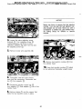
Model Views
I
3208 Naturally Aspirated Engine
Positive Crankcase Ventilation Valves (PCV)
"3208 Turbocharged Engine
Fuel Priming Pump
EGF] Valve
3208 Engine with Low Emission
System (L.E.S.)
7
MIMS Machinery Movers mimsriggers.com
Serial Number and
Information Plate Location
General lnformatI'On
serial Number- Plate (Earlier Engines)
The Caterpillar 3208 Truck Engine is a
lO.4 liters (636 cu. in.) displacement, ll4
mm (4,5 in.) bore, l27 mm (5.0 in.)
strokel four stroke cycle] 8 cylinder goo
Vee design engine. The firing order is 12-7-3-4-5-6-8 and the direction of rotation is
counterclockwise, as viewed from the
flywheel. The engine can either be naturally
aspirated, turbocharged or turbocharged
aftercooledl with direct fuel injection.
A mechanical governor controls the fuel
injection pump output to maintain the engine
rpm selected by the operator.
Located on the right rear side of the
cylinder block.
Individual injection pumps, one for each
cylinder, meter and pump fuel under high
Serial Number Plate (Later Engines)
pressure to an injection valve for each
cylinder.
The cooling system consists of a belt
driven centrifugal pump' with two
thermostats which regulate engine coolant
temperature) an oil cooler and a radiator
incorporating a- shunt system.
The engine lubricating oil is supplied by a
gear-type pump, which is both cooled and
filtered. Bypass valves provide
unrestricted flow of lubrication oil to the
engine parts when oil viscosity is high, or
if either the oil cooler or the oil filter
Located on the left front side of the
cylinder block.
elements should become clogged.
Information plate
Efficiency of emission controls and engine
performance depends on adherence to
proper operation and maintenance
recommendations, and use of recommended
fuels and lubrication oils.
Follow the recommended maintenance
schedule with special emphasis on emission
related components.
For Engines Used in California
Low Emissioh System (L E.S.) Caterpillar
3208 Truck Engines with exhaust gas
recirculatio.n. These engines are equipped
with an exhaust gas recirculation valve,
which on engine start-up, directs some of
the exhaust gases to the inlet manifold to
Located on the left valve cover.
should the water pump be replaced.
be burned again. At full load there is no
exhaust gas recirculation'
8
u
MIMS Machinery Movers mimsriggers.com
Gauges
i
your truck may not have the same or all
of the gauges as shown in the illustrations.
The illustrations shown are oi typical
gauges:
Gauges provide a "look"
engine., Be sure they are
order. You can determine
"normal" -operating. range
inside the
in good working
what is
by observing the
gauges, over a period of time. The cause
of any "sudden or significant c)hange in the
readings should be determin6d and
corrected.
engine coolant temperature. lt
should normally indicate between
(160oF) and -93oC
(200OF).
©Water7lOC
Temperature
Indicates
Somewhat higher temperatures may occur
under certain conditions. Maximum allowable
temperature is 99oC (210oF) with the
cooling system pressurized.
®Oil
:Iopuiasauereb.eTwheee3iI2P4rOeSaSnu:e480
kPa (35 and
70 psi) when
the
Pressure
- Indicates
engine
engine is running at rated engine speedl
with SAElOW/30 oil, at operating
temperature. A lower pressure is normal
at low idling speed. lf no pressure is
indicatedl stop the engine.
amount of charge or discharge in
the battery charging circuit.
Normal- operation
of the
©Ammeter
Indicates
theindicator
should be slightly to the positive (right)
side of "0" (zero).
With the engine running, during normal
operationl if the indicator is constantly to
the negative (left) side of "0" (zero) or
O
shows excessive charge, have the charging
system checked for malfunction.
MIMS Machinery Movers mimsriggers.com
Gauges
rpm (speed). The engine can be
operated between rated speed
pressure to the injection pump.
The indicator should register in
the NORMAL
(green) range.
When
Pressure
- Indicates
fuel
and high -idle
without damage,
©Tachometer
Indicates
enginebut
should not be allowed to overspeed (such
the filter element becomes clogged the
as when going downh"I).
indicator will move to the OUT position.
©Fuel
Fuel Level - Indicates fuel level
Service Hour Meter - Indicates
in the fuel tank. Electrically
the total number of hours the
engine has operated.
operated, it registers only when
the key switch is ON.
10
MIMS Machinery Movers mimsriggers.com
Before Starting the
Engine
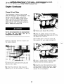
Under the Hood Inspection
For maximum service life of your truck
engine, 'make a thorough under the hood
inspection before starting thel engine.
Look folr such items as oil or coolant leaks!
loose bolts, worn fan belts and trash
buildup. Remove trash buildup and have
repairs made as needed.
I
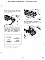
5. Inspect the engine fo-r oil leaks, such
as front and rear seals, crankcasel oil filters
and valve covers.
6_ Inspect the fuel system for leaks]
loose fuel line clamps and fittings and loose
or worn hoses'
1. Inspect the radiator for leaks and
trash buildup'
2- lnsbect the radiator and icv hoses
for cracks and loose clamps.
7- Inspect wiring for loose.connections
and worn or frayed wires.
¬;
8. Inspect air intake system hoses and
elbows for cracks and loose clamps.
9, Inspect engine-to-frame ground -strap
for good connection and condition.
3. Inspect the fan, water pump and
accessory drive belts for cracks] breaks
and frayed edges. Belts for multiple
groove pulleys are sold in matched sets'
O
4- Inspect the water pump for leaks.
Slight evidence of coolant from the drain
. hole is normal'
iI
MIMS Machinery Movers mimsriggers.com
Before Starting the
Engine
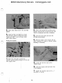
Pre-Start Checks
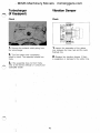
5- observe the air cleaner service
i- Measure the crankcase oil level. The
correct oil level is shown by the marks just
below the words FULL and ADD on the
d'lpstick. Two dots are currently used to
indicate the correct level. Some earlier
dipsticks have a line across the dipstick in
the same location, Keep the oil level
between these marks. Never use _the words
themselvesl to measure the oil level.
indicator (if equipped). Service the air
cleaner when the yellow diaphragm enters
the red zone or the red-piston locks in the
visible position.
Fuel leaked or spilled onto hot surfaces or
electrical components can cause a fire.
2l check the coolant level.with the
engine stopped and cold. F]emove the
radiator cap slowly to relieve pressure.
3. Maintain the coolant level to within l3
6I Drain water from the water separator'
mm (1/2.inch) of the bottom of the fill pipe.
Install the radiator cap.
4l lf equipped with a sight glassl
maintain the coolant to the proper level.
12
MIMS Machinery Movers mimsriggers.com
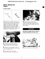
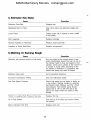
Starting the Engine
Below -12OC (10oF)
Above -12OC (10oF)
Caterpillar 3208 Truck Engines are
designed to start at temperatures above -12oC (10oF) without usingitarting
aids. lf the temperature is below -12oC
(looF),,la starting' aid may be necessary
and/or 'cylinder block coolant heater may
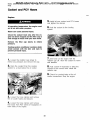
Use starting fluid sparingly and SPray it
only while cranking the engine. Follow
manufacturer,s instructions carefully.
be needed or crankcase oil tray need to
be heated.
Do not store starting fluid containers in
the cab.
1- place the transmission controls in
NEUTF]AL and d'lsengage the, flywheel clutch)
if so equipped.
I
1- Follow steps i and 2 for "Above
2. push down on the accelerator pedal
to the floor once and then release to low
idle
-12oC (10oF)."
position.
2, Turn the starter switch to the STAF]T
position.
3, Turn the starter switch to|he START
position. lf the engine fails to start within 30
seconds, release the starter switch and
wait 2 minutes to allow the starter motor to
NOTICE
cool before using it again.
4- As soon as the engine starts, release
the starter switch and reduce engine rpm to
Excessive ether can cause piston and ring
damage. Use ether for cold starting purposes
low idle.
only-
5l Do not apply load to the'engine or
increase engine rpm until the oil pressure
gauge indicates normal.
3l spray starting fluid into the precleaner
for one second while cranking the engine.
6, operate the engine at low load and
Wait at least two seconds before
low rpm until the coolant temperature is
spraying starting fluid again.
66oC (1500F) or higher. Check all
gauges during the warmup period.
4- F]elease the starter switch when the
engine starts and reduce engine rpm to low
idlel
5. operate the engine at low load and
low rpm until the coolant temperature is
66oC (150oF) or higher. Check all
gauges during the warmup period.
O
13
MIMS Machinery Movers mimsriggers.com
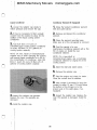
Starting the Engine
Starting With Boost Cables
Batteries..gl've off flammable fumes that
can explode-.
Prevent sparks near the batteries. They
could cause vapors to explodeI Do not all
low battery cable ends to contact each
other or the engine.
Do not smoke when obserying the battery
electrolyte levels.
ll- Fasten the positive (+) clamp of the
boost cable to the positive (+) post of the.
battery.
EIectrolyte is an acid and can cause per.
sonal injury if it contacts skin or eyes-
Always
wear
protective
glasses
when
2- Fasten the negative (-) clamp of the
boost cable to the truck frame away from
working with batteries-
and below the battery,
3I Start the engine'
NOTICE
4I After the engine startsl disconnect the
negative (-) cable from the truck frame.
Your engine may have a 12 or 24 Volt starting system. Use only the same voltage for
boost starting. The use of a higher voltage
will damage the low emission system.
5_ Disconnect the positive (+) cable
from the battery.
Always connect the boost cables in parallel
with the truck battery cables, NEGATIVE (-)
to NEGATIVE (-) and POSITIVE (+) to
POSITIVE (+).
Do not reverse the battery cables. The alternator can be damaged.
Attach ground cable last and remove first.
14
MIMS Machinery Movers mimsriggers.com
Operating the Engine
Proper operation and maintenance are
The naturally aspirated engines can be
operated at full load down to 1900 rpm and
may be Operated for short periods at_full
load down to t400 rpm, Operation at full
load below l400 rpm is not
recommended, How6ver, 3208 engines maly
be operated below 1400 rpm at light
loads and low truck speeds. ln fact)
operation below l400 rpm at light loads
is recommended to achieve the best fuel
economy, using the progressive shifting _
key factors in obtaining the maximum life
and economy of Caterpillar truck engines.
Following the directions in this guide will
lower operating costs.
I
1- After normal oil pressu-re "is reachedl
operate the engine at low load until the
temperature gauge begins to move before
operating at full load.
I
technique.
2.llSelgc"he lowest gear for a smooth!
easy, start without slipping the clutch. Avoid
Upgrade Operation
jerky starts which put unnecessary stress
on the drive train.
1- upgrade operation varies between
turbocharged and naturally aspirated engine)
due to the differences in minimum rpml
where full load operation is recommended'
3l use, progressive shifting to reduce fuel
cohsuinption. progressive shifting is using
only the rpm required to make.an upshift
(See NOTE above).
into the next gear. The amount of rpm
required to make an upshift increases as
the truck speed increases or if upshifts are
made on upgrades. Experience with your
truck will show you how much rpm is
required to -make upshifts under various
2_ Truck performance on upgrades is
normally improved by eliminating
unnecessary shifting on either
turbocharged or naturally aspirated engines.
Turbocharged engines will operate at full
load at a lower rpm and require less shifting
than naturally aspirated engines.
conditions.
4. when the desired speed is reached, if
the truck can be operated in more than one
gear, select the gear that allows the
Downgrade Operation
lowest rpm (the highest gear) that will.pull
the load.
NOTICE
NOTE: Caterpillar manufactures both
turbocharged and naturally aspirated (nonturbocharged) 3208 engines, The
operating requirements of each are different.
Do NOT allow the engine rpm to exceed the
maximum rated rpm of the engine.
The turbocharged engines may be
operated at full loadl at any rpm betwe6n
rated engine speed and l400 rpm.
i. on a downgrade, do not coast or put
the transmission in neutral.
I
2, select the correct gear that does not
allow the engine rpm to go more than 200
rpm above rated speed.
ll
I
3- A simple rule to follow is to select the
same gear that would be required to go up
the grade.
15
MIMS Machinery Movers mimsriggers.com
Stopping the Engine
Maintenance
Recommendations
Cooling System
Before stopping the engine when the
engine is operated at low loadsl the engine
needs to run at low idle about 30
seconds before it is stopped. But, if the
engine is operated at highway speeds
where the engine was operated at high
loads, the engine should be run at low
idle for 3 minutes to reduce and stabilize
internal engine temperature.
NOTICE
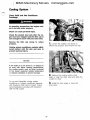
Never add coolant to an overheated engine;
allow the engine to cool first.
check the specific gravity of the antifreeze I
solution frequently in cold weather to ensure I
adequate protection-
To stop the engine, use the method listed
that applies to the shutoff system on your
lf the engine is to be stored in, or shipped to,
an area with below freezing temperatures;
the cooling system must be protected against.
freezing to the lowest expected outside
temperature.
truck.
1, Turn the key switch to the OFF
positionI Or I
2..
All water is corrosive at engine operating
temperature. The cooling system should be
protected with conditioner at all times regardless of the concentration of antifreeze. This I
can be.done by either using caterpillar cool- I
ant conditioner elements, or by maintaining a
, pull OUT the manual shutoff
control]
or..
3... push lN and hold the stop button
until the engine stops, then release the
button.
3eyo to 6% concentration of liquid Caterpillar
cooling system conditioner, or equivalent.
Make sure the shutoff procedure is
understood. F]efer to the truck
manufacturer's instructions for your type
of engine shutoff system used.
To prevent over inhibiting the cooling system,
never use both liquid cooling system conditioner and coolant conditioner elements at the
same time.
Do not use Caterpillar cooling system conditioner or coolant conditioner elements with
Dowtherm 209 Full-Fill coolant. Follow the instructions provided with the Dowtherm 209
Full-Fill coolant.
I
Cooling System Conditioner Liquid
Maintain a 3O/o to 60/o concentration of
liquid Caterpillar cooling system conditionerl
or equivalent. Add the correct amount of
cooling system conditioner at every oil
change interval. Use 0.24 liters (i/2 pint)
conditioner per 38 liters
(10 U.S,
gallons)
of cooling system capacity. On newt
rebuilt or remanufactured engines and when
changing coolant, use 0.95 liters (1 quart)
of conditioner per 30 liters (8 U.S, gallons)
of cooling system capacity.
16
MIMS Machinery Movers mimsriggers.com
Fuel System
Coolant Conditioner Elements
NOTICE
For engines equipped with coolant
conditioner elementsl install a new
maintenance element at every oil change
interval. Use a precharge element only when
Fill the fuel tank at the end of each day of
operation to drive out moist air and to prevent condensation. Do not fill the tank to the
top. The fuel expands as it gets warm and
may overflow.
filling the system on newt rebuilt or
remanufactured engines, or changing
coolant, Your Caterpillar dealer can
provide you with the correct coolant
Do not fill the fuel filters with fuel before in-
conditioner element.
stalling them. Contaminated fuel will cause
accelerated wear to the fuel system parts.
General
coolant should be drained a'nd replaced
every 2400 service hours or'2 year) when
Caterpillar cooling system conditioner, or
equivalentl is added) as recommended.
After changing the fuel filtersl bleed the
fuel system to remove air bubbles from the
system.
Premix antifreeze solution to provide
protection to the lowest expected outside
Drain water and sediment from the water
separator daily and the fuel storage tank
temperature. Pure undiluted antifreeze will
freeze at -23OC (-10oF).
weekly] and before the tank is refilled.
This will help prevent water or sediment
A mixture of 500/o ethylene glycol and
500/o water will protect the coolant from
from being pumped from the storage tank
into the engine fuel tank.
freezing down to a temperature of
-37oC (-34oF).
Use only fuel as recommended in the
"Coolant; Fuel and Lubricant Specifications"
Use clean water that is low in scale
forming mineral. Do not use softened water.
section of this guide.
Filling at over 20 liters (5 U.S. gallons)
Air Intake System
per minute can cause air pockets in the
Service the engine air cleaner at regular
intervals as determined by the truck
manufacturer's recommendations and dust
cooling system.
After draining and refilling the cooling
conditions.
system, start and operate the engine with
the fill cap off until the coolant level
An air cleaner service indicator may be
mounted on the dash panel or in the engine
compartment. A colored piston showing in
the window indicates the need for servicing
the air cleaner. Replace the filter element
at least once a year.
stabilizes. Add coolant as necessary to fill
the system.
Operate with a thermostat in the cooling
system year-round. Overheating will occur
without a thermostat.
Inspect the air intake system hosesl
elbows and gaskets for cracks or damage)
replace as needed. Check for loose
clampsl tighten as needed.
O
Check the precleaner (if equipped) daily
for accumulation of dust and debris.
17
-
MIMS Machinery Movers mimsriggers.com
Maintenance
Recommendatidns
Scheduled Oil Sampling (S-O-S)
General
Use Scheduled Oil Sampling (S-O-S) to
monitor the condition and maintenance
requirements of your equipment. Each oil
sample should be taken when the oil is hot
and well mixed) to ensu.re that the sample
is representative of the oil in the
compartment.
Follow a scheduled preventive
maintenance program.
Consult your Caterpillar dealer for
complete information and assistance in
establishing a S-O-S program for your
equipment.
Accumulated grease and oil on the engine is
a fire hazard.
NOTICE
Fiemove the grease, oil and debris at least
every 1000 hours and each time any signifi-
EIectricaI System
cant quantity of oil is spilled on the engine.
Caterpillar 3208 Truck Engines installed in
trucks without an engine-to-frame ground
strap can be damaged by electrical
discharge.
To prevent electrical discharge damage)
check to make sure the truck's electrical
system has an engine-to-frame ground I
strap. For trucks which have the alternator
connected to an engine component, the
ground strap must connect that component
to the frame.
NOTICE
Some vehicles have starter-to-frame ground
straps. But, many of these starters are not
electrically grounded to the engine. They
have
internal
electrical
insulation
systems-
For this reason, the starter-to-frame ground
strap may not be an acceptable ground. Use
a separate engine-to-frame ground strap.
When boost starting the engine, follow the instructions in the "Operation Section-"
Your engine may have a 12 or 24 Volt starting system.. Use only the same voltage for
boost starting. The use of a higher voltage or
a welder will damage the electrical system
and the low emission system (L.E.S.).
18
MIMS Machinery Movers mimsriggers.com
coolant, Fuel and
O
Lubricant Specifications
coolant specifications
I
Antifreeze
NOTICE
Use ethylene glycol-type antifreeze, Use
the correct amount, mixed with water) to
provide freeze protection to the lowest
expected outside_ temperature'
Use a mixture of water) antifreeze and cooling
system
conditioner. :lpure,
undiluted
antifreeze will freeze at -230C (-1OOF).
Cooling System Conditioner (Liquid)
AIways add cooling system conditioner to water, or install a coolant conditioner element (if
equipped). Never use water only.
Use Caterpillar cooling System conditioner
or equivalent. Add the correct amount of
cooling system conditioner at every oil
change interval to maintain a 30/o to 60/o
concentration. Conditioner can be
purchased from `your caterpillar dealer.
To prevent over inhibiting the cooling system,
never luse both liquid cooljr]g system conditioner,and a coolant conditioner element (if
eduipF)ed) at the Same time.
Coolant Conditioner Elements (lf Equipped)
Do not use Caterpillar cooling system conditioner " or coolant conditioner elements with
Coolant conditioner elements should be
used to maintain a 30/o to 60/o concentration
of conditioner. Install a new maintenance
element at every oil change interval, Use a
Dowtherm 209 Full-Fill coolant. Follow the in-
structions provided with the Dowtherm 209
Full-Fill coolant-
precharge element when filling the
complete system or changing coolant. Your_Caterpillar dealer can provide you with the
correct coolant conditioner element.
I
Refer Ilo "Know Your Cooling System)"
Form 'SEBDO518, for more detailed
specifications and instructiohs on water
and c6oling system conditioner sambling
and testing.
Fuel Specifications and Information
Types of Fuel
Caterpillar diesel engines have the ability
to burn a wide variety of fuels..These fuels
are divided into two general groupsI
watei,I
Acceptable water for use in the ethylene
glycol-type antifreeze and water mixture is
shown in the chart below:
preferred and permissible.
The preferred fuels provide maximum
engine service life-and performance. They
are distillate fuels. They are commonly.
Acceptable Water
50% Antifreeze
50% Water
Without
Antifreeze
Chlorides
loo ppm
or less
50 ppm
or less
Sulfates
100 ppm
or less
50 ppm
200 ppm
or less
100 ppm
50O ppm
or less
250 ppm
or less
6.5 or higher
6.5 or higher
Water Content
Hardness as
CaCo3
Dissolved Solids
O
I
`
pH
called diesel fuel, furnace oill gas oil or
kerosene.
The permissible fuels'are crude o"s-or
blended fuels. Use of these fuels can result
in higher maintenance. costs and reduced
or less_
engine service life.
or less
ppm - parts per million
19
-..
MIMS Machinery Movers mimsriggers.com
coolant, Fuel and
Lubricant Specifications
Lubricant Specifications
F]efer to "Fuels for Caterpillar Diesel
Engines," Form SEHS7067, for a detailed
summary of preferred and permissible
fuels and their specifications.
The abbreviations listed below follow
S,A,E. J754 nomenclature. The
classifications follow S.A,E. Jl83
classifications. The MIL specifications are
F3efer to S.A.E. J313 Diesel Fuels for
definitions will be of assistance in
U.S.A. Military Specifications. These
information about better quality fuels, such
purchasing lubricants. The recommended
oil vjscosities are found on the
"F]ecommended Lubricant Viscosities"
as ignition qualityl gravity/denSity!
viscosity] cloud pointl sulfur contentl etc.
chart.
Fuel Sulfur Content
The prefix "SPC" is a general
abbreviation used by Caterpillar to identify
special oils such as synthetics or semi-
The percentage of sulfur in the fuel will
affect the engine oil recommendations. lf the
fuel has over 0.50/o sulfur content] the
synthetic oils.
CD/SE or CD/SF engine oil must have a
TBN of 20 times the percentage of fuel
sulfur (TBN as measured by the ASTM D2896 method)I
Engine Oils
Use o"s that meet the Engine Service
Classification CD/SE or CD/SF (MIL-L-
Fuel sulfur is chemically changed during
combustion to form sulfuric acids. The acid
2104D) or CC/SE or CC/SF
(MIL-L-46152B).
chemically attacks metal surfaces and
causes corrosive wear. Higher engine oil
Consult the "EMA Lubricating Oils Data
Book," Form SEBU5939, for a listing of
TBN values are essential to minimize
corrosive wear.
CD/SE, CD/SF, CC/SE and CC/SF oil
brands.
Periodically request fuel sulfur content
information from your fuel supplier. Fuel
The percentage of sulfur in the fuel will
affect the engine oil recommendations. lf the
fuel has over 0.5O/o sulfur contentl the
sulfur content can change with each bulk
delivery.
Fuel Cetane Fiequirement
CD/SE or CD/SF engine oil must have a
TBN of 20 times the percentage of fuel
sulfur (TBN as measured by the ASTM D2896 method).
-
The minimum fuel cetane number
recommended for the direct injection engine
is40.
Higher TEN values are essential to retard
the corrosive damage to metal engine parts.
Fuel Cloud Point
Your oil supplier should be able to furnish
the correct oils'
Fuel waxing can plug the fuel filters in
cold weather. The fuel cloud point must be
below the temperature of the surrounding
air to prevent filter waxing and power loss.
Fuel heating attachments are available
from your Caterpillar dealer to minimize fuel
Lubricating Grease (MPG)
Use Multipurpose-type Grease (MPG).
Multipurpose-type grease which contains 3O/o
filter waxing.
to 5O/o molybdenum disulfjde (MPGM) is
preferred. NLGI No. 2 Grade is suitable for
most temperatures. Use NLGI No. i or
No. 0 Grade for extremely low temperatures.
20
MIMS Machinery Movers mimsriggers.com
Oil and Filter Change
O Interval (lVIileage)
M'[leage and Kilometer Conversion
Chart
To use the "Mileage Oil and Filter
The recommended oil and filter change
interval in service hours of engine operation
the APl classification of oil used and the
crankcase capacity are given in the "Oil
and Filter Change Interval Chart."
Change Interval Chart" shown belowl
determine the hour change interval from
the "Lubrication and Maintenance Chart" by
the classification of oil used and the
crankcase capacity.
The oil and filter change intervall as
noted in the "Lubrication and Maintenance
Use this hour figure and the calculated
average MPH figure as cross reference on
Chart)" may be too long when a truck is
not equipped with an engine service hour
meter and the odometer mileage is used
the chart, to determine the approximate
for determining the change interval.
Examples of this type of application are
blank space provided in the "Lubrication
and Maintenance Chart" under "Oil and
concrete mixersl garbage Packers and fire
Filter Change
mileage interval for oil and filter changes.
This mileage figure may be written in the
Interval."
trucks.
O
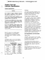
Mileage Oil and Filter Chang e
lnterv al Chart
(Approximate)
To use mileage as a change interval,
calculate the number of miles the truck
travels per week or month and divide this
figure by the number of hours the engine
operates per week or month. This answer
will give you the average miles per hour
AverageMPH(km/h)
Oil Change Interval in Hours
150 hr.
(MPH) the truck operates. The average
MPH figure times the hour interval, from the
"Lubrication and Maintenance Chart" will
give you the approximate number of miles
to be used for oil and filter changes.
2,00O mi
3,000 mi
(l6)
2,400 km
3,200 km
418OOkm
3,00O mi
41800 km
7,250 km
15
2,250 mi
(24)
3,GOO km
20
(32)
3,OOO mi
4,OOO mi
6,000 mi
4,8OO km
6,500 km
9.coo km
25
(40)
3,750 mi
5,000 mi
7,5OO mi
6'OOO km
81000 km
12'000 km
4,500 mi
7,250 km
6,000 mi
9,60O km
9,00O mi
14,500 km
5,250 mi
8,5OO km
7,000 mi
ll,000 km
17100O km
30
week divided(i)by an average 30 hours
per week of engine operation, equals (-)
(48)
35
(56)
(-) 6000 miles approximately for the oil
and filter change interval.
21
BOB hr+
1,500 mi
Example: 600 miles of truck operation per
an average of 20 miles per hour (MPH)I
times a 300 hour change interval) equals
200 hr.
10
4,5OOmi
1O,500 mi
40
6,000 mi
8,000 mi
12,OOO mi
(64)
9,6OO km
1310OO km
191000 km
.
.
MIMS Machinery Movers mimsriggers.com
Refill Capacities -
Oil and Filter Change
Interval (Service Hours of
Engine Operation)
(Approximate)
Compartment
or System
Imperial
U.S.
Quarts
Liters
Minimum AP I Oil CIassification When Diesel Fuel
Sulfur Content is 0.5% or
Quarts
ENGINE CF]ANKCASE including FILTEF]S(1)
Crankcase RefillCapacity lnclud-ingFilters(U.S.
Serial No.32Y68441-Up,51Z1-Up
Less
CD/SE or
CC/SE or
15
Quarts)
CD/SF(1)
CC/SF(1)
1 1.5(2)
1 O(2)
l8 and 20 quarts
300 Service
or13
or ll.5
(TurbochargedEngines)
Hours
Not Flecommended(3)
l8 quarts
300 Service
200 Service
17
15
(Non-TurbochargedEngines)
Hours
Hours
18 quarts
20O Service
150 Service
16.5
(Non-TurbochargedEngines)CaliforniaL.E.S.(2)
Hours L.E.S.(2)
Hours L.E.S.(2)
l4 quarts
200 Service
(Non-TurbochargedEngines)
Hours
150 Service
Hours
18
17
Serial No.
I 2(2)
40S1-Up
or14
18
Serial No. 2Z1-Up(3)(Californiaarrangementsonly)
Serial No. 2Z1-Up(4)(allarrangementsexceptCalifornia)
20
19
Serial No-32Y32i81-32Y68440
Serial No.
32Y1 - 32Y3218O
14
13
ll.5
1 2(2)
1 1.5(2)
10(2)
or14
or 13
or ll.5
Cooling System - See Truck Mfg. Specifications
(1)lf fuel contains more than o.5% sulfur use only CD/SE or CD/SF
(1)Additional oil is required with the use of auxiliary filters. Make sure to
oil with a TBN of 20 times the percentage of fuel sulfur.
add enough oil to fill the auxiliary oil circuit.
(2)Natura"y Aspirated engines equipped with Low Emission System
(2)These engines originally had an 1 1.5 liters (12 U.S. quarts) capacity.
(L.E.S.) exhaust gas recirculation.
The dipsticks on these engines should be re-marked for 13 liters (14
U.S. quarts) capacity. Consult your Caterpillar engine dealer for proce-
(3)cc/sE and CC/SF oils are not recommended for turbocharged
engines.
dure.
(3)Turbocharged engines WITHOUT piston coolingjets should use these
Coolant Conditioner
refill capacities. These engines will have an engine oil cooler that is
approximately 254 mm (10" long).
(4)Turbocharged engines WITH piston cooling jets should use these refill
Cooling system coolant conditioner is
necessary to prevent cylinder wall pitting.
Most antifreeze solutions DO NOT contain
sufficient coolant conditioners. See topics
"Cooling System," "Coolant, Fuel and
capacities. These engines will have an engine oil cooler that is approximately 356 mm (14" long).
-
NOTE: For remanufactured engines, use the Reference Serial No. (F]EF.
SEFi- NO.) to determine the crankcase refill capacity. F3emanufactured
engines with F]EFi. SEF3. NO. 40S1-Up and 32Y1-32Y68440 have the
correct dipstick markings for 13 liters (14 U.S. quarts) capacity.
Lubricant Specifications" and "Maintenant)e
Recommendations. "
Recommended Lubricant Viscosities
For Use At Outside Temperatures From -30oC (-22oF) lo +50oC (+122OF)*
Outside
Temperature
oC
oF
-3O
-22
-2O
- 4
I
I
-10
+14
I
I
0
+10
+5O
+32
I
I
I
I
I
+20
+68
+30
+86
+ 40
+1O4
+ 50
+122
SAE stow-2O
I
I
I
I
9RE fNV-co
CD/SE,
CD/SF,CC/SEOrCC/SF
I
I
I
I
I
I
I
I
I
SAE tow
I
I
I
I
SagiI
I
I
I
I_
I
I
I
I
I
I
I
I
SAI 16WLco
I
I
I
I
I
I
SAE so
I
I
I
I
SAE co
I
I
I
I
I
I
I
Outside
oC
-3O
-2O
-1O
0
+10
+20
+3O
+ 4O
+ 50
Temperature
OF
-22
- 4
+14
+32
+5O
+68
+86
+1O4
+l22
`When operating below -30oC (-22oF) refer to the Cold Weather Operation Guide' Form SEBU5338, available from your
Caterpillar dealer.
22
MIMS Machinery Movers mimsriggers.com
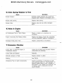
Lubrication and Maintenance Chart
I Lube-
Service
Item
Page
Daily
Engine Crankcase(2)
CD/SE,(EngineStopped)(2)CD/SF,CC/SEorCC/SF 24
Measure oil level.
II
Cooling System
Check coolant level - inspect.
Water Separator
Drain water and sediment - inspect.
24
25
Air Tank (lf Equipped)
Drain water and sediment.
27
Under the Hood Inspection
Inspect engine compartment.
27
First Oil Change Interval Only - New, FIebuilt or F]emanufactured Engines
Engine Valve Lash
NOTE: Check and adjust at first oil change interval.
Then Every 120O Service Hours or One year.
scheduled oil change interval, due to initial
wear and seating of valve train compo-nents.
Oil and Filter Change Interval
Every
Service Hours or 3 Months or
Engine Crankcase(2)
NOTE: Make sure to fill in the number of service hours
in the blank space above for the oil and filter change
interval. This interval in service hours is determined
by the crankcase capacity and the API classificationIofoilused.F]efertothetwochartsonpage22.
29
Check and adjust valve lash at the first
km (
Miles) Whichever Occurs First
Change oil and filters - if mileage figures
are to be used to determine the service
interval, see page 21 "Oil and Filter
Change Interval (Mileage)" for method
and procedure.
CD/SE,
CD/SF,
CC/SE o'r
30
CC/SF
(2)
I.1
Fuel Filters
Fieplace.
32
Engine Crankcase Breather (lf Equipped)(1)
Clean.
34
Cooling System
Add coolant conditioner or replace ele-ment.cleanradiatorfins-inspect.
Air Cleaner
Clean or replace elements-or at intervalrecommendedbytruckmanufactllrer.
36
Batteries
Clean - check electrolyte level.
AIternator, Fan and Accessory Drive Belts
flow Emission System (L.E.S.)
Check - adjust.
38
38
39
34
Every 1200 Service Hours or One Year or
--
Check for correct operation.
km (
Miles) Whichever Occurs First
Engine Valve Lash
Check and adjust.
Air-Fuel Ratio Control (Turbocharged)
'PCV Valve (lf Equipped)
Check setting - adjust if necessary.
Check diaphragms - replace if neces-Sary.
Thermostats
Check - replace if necessary.
Check - repair or replace if necessary.
Check - replace if necessary.
'Turbocharger (lf Equipped)
Vibration Damper
Every 2400 Service Hours or Two Years or
km (
40
43
43
44
45
45
Miles) Whichever Occurs First
Coolant and PCV Hoses
F]eplace.
Cooling System
Clean, conditioner precharge.
*Fuel Injection Nozzles
Test - replace if necessary.
Governor
Check full load speed (set point) and lowidlerpm.
46
47
49
52
NOTE: Mileage and kilometer figures have been left blank and w"I need to be filled inl if mileage figures are used to determine
the service intervals. Calculate the average miles per hour (mph) or kilometers per hour (km/h) the truck operates. Multiplying the
average mph or km/h figure times (X) the number of service hours for each service interval will equal (-) the service interval in
miles or kilometers. Enter this mileage or kilometer figure in each appropriate blank space in the chart and in the page heading.
'Emission control required- maintenance 'scheduled items.
(1)Engines equipped with Low Emission System (L.E.S.) exhaust gas recifoulation.
(2)cc/sE and CC/SF oils are not recomniended for turbocharged engines.
23
Daily
MIMS Machinery Movers mimsriggers.com
Engine Crankcase
Cooling System
Measure Oil Level (Engine Stopped)
Check Level - Inspect
Hot oil and components can cause person_
al
injury.
Do
not
allow
hot
oil
At operating temperature, the engine cool.
ant is hot and under pressure-
or
COmPOnentS tO COntaCt SkinI
Steam can cause personal injury.
Check the coolant level only after the engine has been stopped and,the filler cap is
cool enough to touch with your bare handFIemove the filler cap slowly to relieve
Pl.eSSure-
Cooling system conditioner contains alkaliAvoid contact with the skin and eyes to
prevent personal injury.
1_ Measure the o" level.
1- check the coolant level with the
engine stopped and cold.
2- Remove the radiator cap slowly to
relieve any pressure.
2- Maintain the oil level between the
FULL and ADD marks on the dipstick, Do
not i"I the crankcase above the FULL
mark.
3. Maintain the coolant level within l3
mm (i/2 inch) below the bottom of the fill
3. Add oil if necessary.
pipe or to the proper level on the sight
glass) if so equipped.
4. Inspect the radiator cap. F]eplace it if
damaged. Install the radiator cap.
5- Inspect and clean the radiator fins.
"24
MIMS Machinery Movers mimsriggers.com
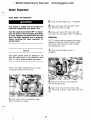
Water Separator
Drain Water and Sediment
2- close the fuel supply line) if equipped.
Fuel leaked or spilled onto hot surfaces or
electrical components can cause a fireI
3- open vent valve ® and drain valve
Turn the disconnect switch OFF or disconnect the battery when changing fuel filters
or water separator elements. Drain_.the fuel
from the water separator into a container
before removing the water separator re-
4. close vent valve o, drain valve ©
©' Allow the water to drain.
and open the fuel supply valvel if equipped.
Replacing
NOTE: Change element anytime the water
separator becomes contaminated enough
that water level cannot be seen through
the transparent cover.
taining clamp-
1- close the fuel supply valve, if
equipped.
NOTICE
The engine should never be allowed to run
I with, the water level in the separator more
than 1/2 full or engine damage may result.
NOTE: The water separatorlis not a filter.
lt separates water from the fuel.
I
I
.
I
2I Remove a" dirt from the separator
and surrounding area.
3- open vent valve o and drain valve
8 A"ow fuel to draln Close valves O and
1, Drain water from trie separator daily
before starting the engine.
O
25
Daily
E=-=-=_i5
I--=-`-`
MIMS Machinery Movers mimsriggers.com
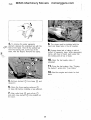
4_ To,remove the water se.parator
element) depress the extended tab with the
8- The clamp must be installed wI.th the
hand and finger tabs in the UP position.
heel of the hand. Then lift the slottad tab
from the locking slotl at the-top of the
base] with the fingers_.IRemov6 the clamp.
9. Eng'age lower tab of clamp in slot at
bottom of separator base. while __d_epressing
cl-amp, with heel of hand, push upper tab
F-+=" ¬\\\.~
into locking slot at top _Qf base.
"``3,; ±rl
1O-. open the fuel supply valve, if
equipped.
ll, prime the fuel system. see "priming
the- System". under.item "Fuel Filters."
12. start the e.ngine and ch:ck for fuel
leaks.
5. Remove elemen_I © from bas_e © and
discard it.
6. clean the three sealing surfaces ©
on base © before installing a new_element
7nldA;lugsnhonu:I:t eleoLeeS 6nqntroo"ppolsnltie on
the base.
26
MIMS Machinery Movers mimsriggers.com
Air Tank (lf Equipped)
Under the Hood
Inspection
Drain Water and Sediment
Inspect the Engine Compartment
For your-own safety and maximum
service life of the engine, make a thorough
inspection under the hood before starting
the engine.
Look for such items as loose bolts]
debris buildupI Oil and COOlant leaks.
F]emove all debris and have repairs made
as needed.
|' open the drain valve on the air tank
and drain the water and sediment. Close
the valve.
1- lnspe-_ct all cooling system hoses for
cracks) splits and leakage. Tighten hose
clamps if neessary.
2. Inspect the water pump for coolant
leaks. Slight evidence of coolant from the
drain hole is normal. Only with consistant
measurable coolant loss should the water
pump be replaced.
O
'27
MIMS Machinery Movers mimsriggers.com
3- Inspect for excessive oil leakage from
the front and rear crankshaft seals.
7_ Inspect engine mounting bolts for
looseness.
4- Look on the ground for an indication
8, Inspect a" wiring for worn or frayed
of oil or coolant leaks.
insulation and loose connections.
9, Make sure the engine-to-frame ground
strap connection is Clean and tight.
5. Inspect for any fuel leakage at
connectionsl lines and hoses.
6- Inspect the oil cooler and pcv hoses
for leaks or damage.
28
MIMS Machinery Movers mimsriggers.com
First Oil Change Interval Only - Newl F]ebuilt or F]emanufactured Engines
Engine Valve Lash
O
Check and Adjust
Initial valve lash adjustment on new]
rebuilt or remanufactured engines is
recommended at the first scheduled oil
change interval, due to initial wear and
seating of valve train components.
For the procedurel see topic "Engine
ValvellLash" in "Every 1200 Service Hours
or i Year) Whichever Occurs First'"
O
O
29
MIMS Machinery Movers mimsriggers.com
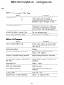
Oil and Filter Change Interval - Every
Service Hours or 3 Months
Miles) Whichever Occurs First
Engine Crankcase
Change Oil and Filters
The percentage of sulfur in the fuel will
affect the engine oil recommendations. lf the
fuel has over 0.5O/o sulfur content, the
CD/SE or CD/SF engine oil must have a
TBN of 20 times the percentage of fuel
sulfur (TBN as measured by the ASTM D2896 method). Your oil supplier should be
able to furnish the correct oils.
3- Remove and discard the oil filters'
Hot oil and components can cause personal
injury.
Do
not
allow
hot
oil
or
components to contact skinI
Drain the crankcase with the oil warm and
the engine stopped.
I. F]emove the crankcase drain plug and
4_ wipe the s:aling surface of the filter
element mounting base. Make sure all of the
old gaskets are removed.
NOTE: Make sure to use the correct oil
filter element for your engine arrangment.
5- Apply a small amount of clean engine
oil to the new filter element gaskets.
allow the oil to drain'
6. Install the new filter elements by hand
2, lnsta" the crankcase drain plug and
tightenitto70
±
l4N.m(50
±
10lbft).
unt" the gasket contacts the base. Tighten
the filters 3/4 of a turn more with a filter
wrench. Do not overtighten.
MIMS Machinery Movers mimsriggers.com
9l start and run the engine at low idle
for two minutes. Inspect for oil leaks. Slob
the engine.
7. Fill the crankcase. See "Refill
Capacities. "
NOTICE
|0_ wait lo minutes to allow the oil to
drain back into the crankcase. Check the oil
O
lf equipped with auxiliary oil filters, extra oil
level. Maintain the oil level to the FULL
must be added when filling the crankcase.
mark on the dipstick.
If the extra oil is not added, the auxiliary oil
filter will take priority and the engine may
starve for oil-
8I Before starting the enginel check the
oil level. The oil level should be at or above
the FULL mark on the dipstick.
O
1
?
Service Hours
or 3 Months
MIMS Machinery
Movers
mimsriggers.com
Miles) Whichever Occurs First
Oil. and Filter Change Interval - Every
Fuel Filters
Replace
Final Fuel Filter
Fuel leaked or spilled onto hot surfaces or
electrical components can cause a fire.
Turn the disconnect switch OFF or disconnect the battery when changing fuel filters.
1l stop the engine.
ll- Remove and discard the fuel filter
element.
2- shut off the fuel tank supply valve.
Primary Filter (If Equipped)
I. Loosen nut ® on the filter housing
and remove filter case ©.
2. clean the gasket sealing surface of
the filter base. Make sure all of the old
gasket is removed.
2l Remove element © and Wash it in
cleanl nonflammable solvent.
g;#es:a[u:le6ent © and case ©
32
MIMS Machinery Movers mimsriggers.com
3_ Apply clean diesel fuel to the fuel filter
2. unlock and operate the priming pump
gasket.
plunger until the flow of fuel from the vent
valve is continuous and free of bubbles.
I.
4. Install the i"ter and tighten by hand
until the filter gasket contacts the base.
Tighten the filter i/2 to 3/4 turn more
3_ close the vent valve and lock the
priming pump plunger.
with a filter wrench.
Priming the System
4. start the engine. lf the engine will not
start] continues to misfire or smoke, further
bleeding is necessary.
"
O.
1- open the vent valve on"the fuel
injectl.on pump housing andllturn on the fuel
tank Supply valve.
I
5- Loosen the fuel line nuts at the
cylinder head.
6- crank the engine until fuel flows free
of air bubbles.
7. Tighten the fuel "ne nuts to 40 ± 7
N.m(30
O
33
±
5lbft)I
MIMS Machinery Movers
mimsriggers.com
Service Hours
or 3 Months
Oil and Filter Change Interval - Every
Miles) Whichever Occurs First
Engine Crankcase
Breather (lf Equipped)
Cboling System
Clean
Add Conditioner or F]eplace EIement
NOTE': Truck engines equipped with Low
Emission System (L.E.S.) do not use PCV
valves. A crankcase breather is used on
the valve cover.
At operating temperature, the engine coolant is hot and under pressure.
Steam can cause personal injury-
Check the coolant level only after the en.
gine has been stopped and the filler cap is
cool enough to touch wl.th your bare hand.
Remoye the filler cap slowly to relieve
PreSSureI
Cooling system conditioner contains alkaliAvoid contact with the skin and eyes to
prevent personal injuryll- Loosen hose clamps © and `slide the
hose on to the tube.
J|
NOTICE
2n.dLsoeoaslegolt O, remove breather ©
All water is corrosive at engine operating
temperature. Use Caterpillar liquid cooling
system conditioner or Caterpillar cooling
3- wash breather © in clean]
nonflammable solvent and dry it.
system conditioner. element to treat either
plain water or ethylene glycol antifreeze
solution`.
Never use both the liquid cooling system conditioner and the conditioner element at the
same time-
NOTE: See "Know Your Cooling System"
Form SEBDO518 and your Caterp"lar dealer
for more detailed specifications.
frle::hS:ar"6neTYghsteeanl b?t ad)d ttohel4Cle:nN m
(10
±
2lbft)..
O
5, slide the hose on to bre;ther © and
tighten hose clamps ©.
34
MIMS Machinery Movers mimsriggers.com
Liquid Conditioner
Conditioner Element (If Equipped)
I
i- L3osen the radiator. cab slowly to
relieve pressure and remove the. cap.
i, close :he,.coolant conditioner element
inlet and outlet 'valves. ,
2. lt lmay be necessa,ry to!.drainJeno'ugh
coolant from the radiator td allow for the
2l R,emove and di;card th-e -conaitio-ner
element.,
addition of the liquid cooling system
conditioner.
I
_
I
I,
3-I-ci:an the eleinent mojnting base.
I.
Make sure all of the old gasket'is removed.
3. Add 0.24 liters (1/2 pint) of
Caterpillar liquid cooling system conditioner
for every 38 liters (10.I.S. gallons) of
Cooling system capacityl
4- coat the gasket of a new
mainte`nance conditioner eleinent with a thin
film of engine oil. Install the new
I
conditioner element.
NOTE: on new, rebuilt or remanufactured
engines only or when changing the coolantl
add enough liquid conditioner for a 30/o to
60/o concentration of conditioner. Add 0.95
NOTE: On a new,rebuilt or
remanufactured engine) use a precharge
conditioner element for original fill of the-
liters I(1 quart) for every 3Q liters (8 I.S.
cooling system.
gallons) of cooling system capacity.
5_ open the inlet and outl6t valves.
6I Remove the radiator cap. 7- start the engine and check for leaks. I
Allow the coolant level to. stabilize.
8_ Add coolant if necessary,to bring trie
coolant to within 13 mm (i/2 inch) below
the bottom,of the fill Pipe or to the
proper level on the sight glass, if so
equipped.,
9- Inspect the radiator cap. Replace the
cap if the gasket is damaged, Install the
4- lnspec"he radlator cap gaskets.
Replace the cap if the gaskets are
damaged.
Cap.
5I Install the radiator Cap.
_,,I
I
O
35_
I
Service Hours
or 3 Months or
MIMS Machinery Movers
mimsriggers.com
Oil and Filter Change Interval - Every
Miles) Whichever Occurs First
Engine Air CIeaner
Gleaning Air Cleaner Elements
u
Service the engine air cleaner at regular
intervals determined by dust conditions. See
the truck manufacturer's operator's guide
for detailed information.
Pressure air can cause personal injury-
A service indicator may be mounted on
the instrument panel or in the engine
compartment. A colored piston showing in
the window indicates the need for servicing
the air cleaner. Replace the f"ter element
at least once a year.
When using pressure air for cleaning7 Wear
a protective face shield, protective clothing and protective shoes-
NOTICE
NOTICE
Do not clean filter elements by bumping or
tapping.
Never service the air cleaner with the engine
running.
Do not use filter elements with damaged
pleats, gaskets or seals.
Changing Air Cleaner Elements
NOTE: Air cleaner filter elements can be
cleaned with either air, water or detergent.
1. Loosen the retaining bolts and remove
the end cover on the air cleaner housing.
u
Have spare elements on hand to use
while cleaning used elements.
2- F]emove and Inspect the element for
damaged pleats, gaskets or seals. F]eplace
the element if damaged.
Pressure Air - 2O5 kPa (30 psi)
Maximum Pressure
3. clean the inside of the housing
4. Install a new or cleaned element in
the air cleaner housing.
5I Install the end cover On the air
cleaner housing'
6, F]eset the service indicator by pushing
on the piston plunger.
ll. Direct air inside of the element along
the length of the pleats.
u
36
MIMS Machinery Movers mimsriggers.com
I
2- Direct air on the outsid: of the
2_ Direct water on the outside of the
element along the length of the pleats.
Direct air on the inside along the pleats.
Inspect the element for any rips, tears or
damd,ge.
I
element along the length of the pleats. Air
dry thoroughly before using and inspect
the ,eleinent.
Detergent
pres:ure water - 280 kPa (40 psi)
Maxiinum Pressure
ll. wash the element in warm water and
nonsudsing detergent.
ll- Direct water on the inside of the
elementl along the length of the pleats.
2- Rinse the element with clean water.
See instruction for cleaning with water.
3. Air dry it thoroughly before using and
inspect the element.
Inspecting EIement
1. Insert a light inside of the cleaned and
dry element. Inspect it for rips and tears.
Discard the element if damaged.
2. wrap and store good cleaned
elements in a cleanl dry place.
'l
37
Service Hours
or 3 Months or
MIMS Machinery Movers
mimsriggers.com
Oil and Filter Change Interval - Every
Miles) Whichever Occurs First
Batteries
Alternator, Fan and
Accessory Drive Belts
Clean - Check EIectrolyte Level
Inspect - Adjust
Batteries give off flammable. fumes that
can explode.
Do not smoke when observing the battery
electrolyte levels-
EIectrolyte is an acid and can,cause per.
sonal i,njury if it contacts skin or eyesAlways w6-ar protect-ive
working with batteries.
glasses
when
ll, Inspect-the condition and adjustment
of the belts.
2. To check the belt ;ension, apply ilo
N (25 lbs) of force midway between the
pulleys, Correctly adjusted belts will
deflect l3 to l9 mm (i/2 to 3/4 inch).
To Adjust
1- clean the top of the batteries'
2- Remove the fi"er caps. Maintain the
electrolyte level to the bottom of the filler
openings. lf an addition of water is
necessary, use distilled water. lf not
available, use clean water, low in
minerals. Do not use artificially softened
water.
1l To adjust the alternator drive belt]
loosen mounting bolt O and the adjusting
bracket bolt ©.
2l Move the alternator in or out as
required to-obtain the correct adjustment.
At proper charging rate, batteries should
not require more than 30 cc (1 ounce) of
water per cell Per week.
3l`Install
3- Tighten bolts O and ©.
filler cabs'.
4. lf new belts are installed, check belt
adjustment again after 30 minutes of engine
operation.
38
i
1¬..
"j'. I
I
MIMS Machinery Movers mimsriggers.com
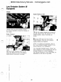
Low Emission System (If
O
Equipped)
Check
Engine F]unning at Idle
Visually check the low emission system
for correct operation at each oil change of
the engine.
1- wth the engine started and running at
low idle speed) lever O should be in the
Engine Stopped
DOWN position, below horizontal] as
shown.
26W\evpeorslgnld:::ent;hteToo#et:I:::on
system tested and repaired.
NOTE: For teS-ting and adjustingl refer to
the "Low Emiss'lon System" Section in the
Service Manuall :Form SEBRO514'
The Caterpillar 6V3060 System Tester has
been designed to test (troubleshoot) the. low
emission system for correct operation.
See Special lnstructionl Form SEHS7808, for
With the engine stopped lever O onl
valve © should be in the up position)
instruction on the rise of -the `tester.
slightly above horizontall aS Shown.
J
O
39
"
I
i-*.
i.
Miles) Whichever Occurs First
MIMS Machinery Movers mimsriggers.com
Every 1200 Service Hours or One Year or
Engine Valve Lash
Check - Adjust
NOTE: Initial valve lash adjustment on
newl rebuilt or remanufactured engines onlyl
is recommended at the first scheduled oil
change interval, due to initial wear and
NOTICE
Adjust the valve lash (clearance) only with
the engine stopped. AIways turn the flywheel
seating of valve train components.
in the direction of normal rotationl which is
When the valve lash (clearance) is
checked, an adjustment is NOT necessary if
the measurement is within the range given
in the "Valve Clearance Check" chart
shown below.
clockwise, as viewed from the front of the
engine.
Valve Clearance Check
Intake
..... ........
Exhaust .. ...,....
0.Solo 0.46 mm (.012 to.018 in)
0.56 to 0.71 mm (.022 to.028 in)
lf the measurement is outside of the valve
clearance check range shown above, an
adjustm-ent.Sis necessary. set the
". - clearance|o the nominal clearance given in
"::+-#-\tshheoJ¥abve?o;!earance setting" chart
Valve CIearance SettI'ng
Intake
.... .........
Exhaust . ........,
0.38 mm (.015 in)
o:64 mm (.025 in)
2- Loosen hose clamps on the
.crankcase ventilation valves or the
crankcase breather and slide the hose
away from them.
To Check and Adjust Valve Lash
(Clearance)
3_ clean around the valve covers'
1- Disconnect the battery or the wire to
Remove both valve covers. -
the shutoff s6Ienoid on the fuel injection
Pump.
To prevent possible injuryJ be Sure fuel
system is shut off and do not use the
Starter motor tO turn the flywheel. Engine
may startt
4_ Turn the crankshaft clockwise (as
viewed from the front of the engine) until
No. 1 cylinder is on top dead center
(TDC-i) compression stroke.
40
MIMS Machinery Movers mimsriggers.com
O
5l Align the TDC-1 mark on the damper .
with the timing pointer located on the front
of the engine block.
8- check and adjust (if necessary) the
intake and exhaust valve lash for No. i and
No. 2 cyl.lnders.
6_ Both the exhaust and inlet valves for
No. i and No. 2 cylinders will be closed.
The four rocker arms should move with
finger pressure. lf both. valves for No, 1
cylinder' are not closed! rotate the engine
360o to obtain TDC-1 compression.
®
"..*_E?.\%.L& \B
9- Loosen the valve adjusting screw
INTAKE
0.38 mm (.015 in.)
FlltINC
locknut.
I)l}DEFl
1|Z!.7,9,4.5,C'B
O
EXHAUST
&5tLS,t\¥t\S
o.64 mm (.O25 in.I)
7l To adjust valve lash] use clearances
shown above. The numbering of cylinders
and valve location are also shown.
I:
O
I.
41
\\
_
`
Miles) Whichever Occurs First
MIMS Machinery Movers mimsriggers.com
Every 1200 Service Hours or One Year or
|5- Turn the crankshaft l80o clockwise
(as viewed from the front of the engine)I
Align the TDC-1 mark on the damper with
the timing pointer.
|6- check and adjust (if necessary) the
intake and exhaust valve lash for No. 4 and
No. 5 cylinders.
|7_ Turn the crankshaft 180o clockviise
(as viewed from the front of the.'engine).
Align the VS timing mark on the damper
with the timing pointer'
10- Turn.the adjusting screw until a
feeler gauge of the correct thickness (see
chart) can be inserted between the valve.
stem and the rocker arm.
18- check and adjust (if necessary) the
intake and exhaust valve lash for No. 6 and
No. 8 cylinders.
lil when the correct adjustment is
obtained, hold the adjusting screw and
tighten the locknutto 32 ± 7 N.m (24 ±
l9- Inspect the valve cover gaskets.
5 lb ft).
Install.new gaskets if necessary.
|2. After the locknut is tightened, check
the adjustment again.
a
O
a
5
1
4 6
7
3
O
O
2
a
a8
O
20- Install the valve covers. Tighten the
bolts in the sequence shown, to l4 ± 3
N.m(10
±
2Ibft)I
|3. Turn the crankshaft l80o clockwise
2ll- connect the hoses to the crankcase
(as viewed from the front of the engine). On
later engines align the VS timing mark on
the damper with the timing pointer.
ventilat'lon valves or the crankcase breather
(If LE.S. equipped) and tighten the hose
clampsto2.3
±
0.2N.m(20
±
2lbin).
14- check and adjust (if-`necessary) the
intake and exhaust valve lash for No. 3 and
22. start the engine and check for o"
No, 7 cylinders.
leaks. Stop the engine.
-- I,.=£J
42
MIMS Machinery Movers mimsriggers.com
Air-Fuel Ratio Control
(Turbocharged Engines
Only)
Check - Adjust
I
2
I
4
3
I-)/Tlm ooo
a
I
# oooo©-.`
Slow engine response and low power may
indicate a need for adjustment or repair.
Your authorized dealers are equipped with
3_.Remove cover O and the spring.
the necessary tools, personnel and
procedures to perform this service.
4I Remove the diaph,ragm assemblyl
inner sleeve © and gasket © from housing
©.
5l Disassemble the diaphragm assembly.
o
pcwalve (If Equipped)
6- clean. and inspect all parts, F]eplace
any part that is worn or damaged.-Always
install a hew gasket and diaphragm when
the PCV valve is disassembled.
FIeplace Diaphragms
7sln:sasenmebJed::eph::agpmhra6m assembly
8. To prevent diaphragm © from
distorting and tearing during assembly, coat
both flange sides of the diaphragm with
gasket cement..Install it with the face
marked "piston face" facing piston ®.
9, coat new gasket © with gasket
cement and install it against the rear face of
inner sleeve ®.
1. clean the outside of the pcv valve(s)
and the area around it. Inspect PCV hoses
for deterioration or damage, replace if
necessary.
|0- lnsta" the diaphragm assembly in
housing ©.
2. F3emove the screws and washers that
hold cover O.in place.
|l. Install the spring and cover ® with
the washers and screws that hold cover O
O
in place.
43
I
Miles) Whichever Occurs
MIMS Machinery Movers mimsriggers.com
Every 1200 Service Hours or One Year or
First
Thermostats
Check - F]ep[ace lf Necessary
5. F3emove the thermostats and gasket
froin the engine block.
At operating temperature, the engine coolant is hot and under pressure.
6- Replace thermostats and gasket.
Steam can cause personal injury.
NOTE: The thermostats should begin
opening (bench test in atmospheric
Check the coolant level only after the engine has been stopped and the filler cap is
cool enough to touch with your bare hand.
pressure) at approximately 80oC to 84OC
(176oF to 183OF). The thermostats should
be fully open at approximately 90oC to
94OC (l94OF to 201oF).
Flemove the filler cap slowly to relieve
Pressure.
Cooling system cond'ItiOner COntainS alkali_
Avoid contact with the skin and eyes to
prevent personal injury.
ll_ Loosen the radiator cap slowly to
relieve any pressure and remove the cap.
2. Drain the coolant from the cooling
system to a level below the thermostat
7- Install the thermostats in the engine
housing.
block.
3- Loosen the hose clamps and remove
the radiator hose from the thermostat
NOTE: Former thermostats may be
reusedl if they meet test specifications
housing.
above and are not damaged or have
excessive buildup of deposits.
8- Install a new gasket and the
thermostat housing on the engine block.
9l lnsta" the radiator hose and tighten
the hose clamps.
10_ Add coolant to the cooling system.
to bring it to the proper level.
ll- start the engine and inspect for
leaks and proper operating temperature.
4- Remove the thermostat housing from
the engine block.
44
MIMS Machinery Movers mimsriggers.com
Turbocharger
Vibration Damper
o (If Equipped)
Check "
Check
1l_ Remove the exhaust outlet piping from
the turb6charger.
ring) between the inner hub and the outer
|l Inspect for separation of the rubber
flywheel ring.
2- Turnlhe turbine and compressor
2_ Replace I:e vibration damper if there
is separation or damage to the rubber ring.
wheel bly hand. The assembly should turn
freely'
O
3- lf the assembly does not turn freely)
refer to the Service Manual or consult your
Caterpillar dealer.
O
45
Miles) Whichever Occurs
MIMS Machinery Movers mimsriggers.com
Every 2400 Service Hours or Two Years or
First
Coolant and PCV Hoses.
IReplace
5- Install all new coolant a'nd PCV hoses
and tighten the clamps.
At operating temperature, the engine cool.
ant is hot and under pressure.
6. Add the coolant to the Cooling
system.
Steam can cause personal injury'
Check the coolant level only after the en.
gine has been stopped and the filler cap is
cool enough to touch with your bare hand.
Ftemove the filler cap slowly to relieve
Pressure.
Cooling system conditioner contains alkaliAvoid contact with the skin and eyes to
prevent personal injury_
7- start and run the engine with the
radiator cap off. Allow the coolant to warm
1l Loosen the radiator cap slowly to
relieve any pressure and remove the cap.
and stabilize.
2. Drain the coolant from the cooling
system to a level below the oil cooler.
8I Add coolant if necessary to brI.ng the
coolant to the correct level. Install the
radiator cap.
9, check for coolant leaks at the oil
cooler connections. Stop the engine.
3l Loosen the hose clamps and remove
the oil cooler hoses and discard.
4- Loosen the hose clamps and remove
the hoses from PCV valves (if equipped) on
both sides of the engine'
46
MIMS Machinery Movers mimsriggers.com
ill
Cooling System
I"
CleapJ Refill and Add Conditioner
Precharge
At operating temperature, lthe engine coolant is hot and under pressure.
Steam can cause personal injury'
Check the coolant level only after the en.
gine has been stopped and the filler cap is
cool enough to touch with your bare handI
FIemoVe the filler cap slowly to relieve
ll- Loosen the radiator cap slowly to
relieve any pressure and remove the cap.
Pressure.
Coolirlg system conditioner contains alkali'
Avoid contact with the skin :and eyes to
prevent personal injury.
NOTICE
lf the engine is to be stored,inl or shipped to
an area with below freezing temperatures)
the cooling system must be either protected
to the lowest expected outside temperature
or drained completely to prevent damage.
2l Remove the coo"ng system -:rain
plugs or open the drain valve and allow the
coolant to drain'
Do not use Caterpillar cooling system
conditioner or coolant conditioner elemerfts
3- Install the drain plugs or close the
with Dowtherm 209 Full-Fill coolant. Follow
drain valve.
recominendations provided with Dowtherm
209 Full-Fill coolant.
I
47
Miles) Whichever Occlirs First
MIMS Machinery Movers mimsriggers.com
Every 2400 Service Hours or Two Years or
4. Fill the cooling system with a cleaning
solution. Use a commercially available
cleaner or 1 kg (2 lb) sodium bisulphate
l1_ Fill the cooling system with the
coolant solution at 20 liters (5 U.S, gallons)
per minute or less to avoid air locks.
per 40 liters (lO U.S. gallons) water.
12- start and run the engine with the
radiator cap removed. Allow the coolant to
warm and the level to stabilize.
5- start and run the engine 1/2 hour.
Stop the engine and drain the cleaning
solution.
13. Add coolant if necessary to bring
6- Flush the system, with engine
stopped) with water unt" the draining water
the coolant level to the bottom of the fill
is clear.
pipe or to the correct level on the sight
glass.
7- Install or close the drain valve. Fill the
system with a commercially available
neutralizer or 250 g (1/2 lb) sodium
carbonate per 40 liters (10 U. S. gallons)
cap gasket. Replace it if damaged. Install
the radiator cap.
|4- check the condition of the radiator
water.
8. start the engine an'd run it for lo
minutes. Stop the engine and drain the
neutralizing solution.
9, Flush the system with clean water until
draining water is clear.
ilo- Mx a solution of acceptable water]
antifreeze and cooling system conditioner or
if equipped with a coolant conditioner
element, install a precharge element. Add
0.95 liters (i quart) of Caterpillar cooling
system conditioner per 30 liters (8 U.S.
gallons) of cooling system capacity (for a
3% to 6O/o concentration)I
NOTICE
lf the engine is equipped with a Caterpillar
coolant conditioner element, to prevent over
inhibiting do not use both the liquid cooling
system conditioner and the coolant conditioner element at the same time.
48
I
MIMS Machinery Movers mimsriggers.com
Fuel Injection Nozzles
I.
I
Thest..I Fteplace lf Necessary
To F]emove Injection Nozzles
Whenever the engine performs in such a
manner that a fuel injection nozzle 'ls
suspected of causing irregular running]
smoking or knocking, isolate each fuel
injection nozzlel one at a time) to determine the malfunctioning nozzle.
NOTE: For complete fuel injection nozzle
testing and cleaning, consult your authorized
Caterpillar engine dealer.
i.
1l clean the area around the valve
COVer'
2, Loosen the hose clamp and
disconnect the hose from the PCV valve(s)
or if low emission system equipped)
disconnect the hose from the crankcase
breather'
ll, Loosen the fuel injection line nut at
the cylinder headl one at a timel with the
engine running. Be sure to tighten each
fuel line nut after the test, before the next
fuel line nut is loosened.
2- when a cylinder is found where the
loosened fuel line nut does not make a
difference in engine performance or
smoking) have that cylinder injection nozzle
tested'
3- F]emove the valve cover.
49
Miles) Whichever Occurs First
MIMS Machinery Movers mimsriggers.com
Every=2400 Service Hours or Two Years or
I
NOTICE
Never use force to remove 'the_fuel injection
nozzles. Turn and pull the fuel injection nozzles straight out by hand. Never pry with a
screwdriver or similar tool. Use 6V4O6l Nozzle Pulling Group for difficult to remove
nozzles.
4- Loosen the valve adjusting screw
locknuts ®. Turn adjusting screw ©
counterclockwise until there is some
clearance between the push rod end and
the adjusting screw ©.
5l Remove rocker arm assembly ©.
9- Remove fuel injection nozzles © from
the cylinder head.
|0. Have fuel injection nozzles © tested
by an authorized Caterpillar engine dealer.
6, Thoroughly clean the area around
each fuel line connection. Disconnect fuel
line © from adapter ©.
fro.mDlasdc:;tneerctd)nles::doen andoazpz[:rllg et of the
cylinder head'
8. Remove clamp ® and the spacer that
holds the fuel injection nozzle in place.
50
MIMS Machinery Movers mimsriggers.com
F
ll
To Install Injection Nozzles
NOTICE
NOTICE
Do not bend the injector inlet line when installing injector into the cylinder head. Bending of
the inlet line creates tension on the injector
I
Never install an injector that has been
dropped without first testing it. Examine the
tip to be sure it is not broken or cracked. Using the Caterpillar 6V3020) 20X scope,
provides a close examination of the nozzle tip
and orifices.
and can cause binding of the needle in the
guide and can result in injector failure.
4- lnsta" fuel injection nozzle ® in the
cylinder head. Turn and push the nozzle into
its correct position. Never put lubricant on
the nozzle or bore in the cylinder head.
cia.,:nos.ta#mn5 ::Tup:::,s,,eocnt,:ned:o2,ean6
2l Make sure the bore in the cylinder
5, Install adapter © in the cylinder head.
Connect the nozzle and fuel injection lines
to the adapter. Tighten the fuel line nuts
to40± 7N.m(30 ± 5lbft).
head and the fuel inlet fittings are clean.
6. Install the spacer and clamp ® that
hold the fuel injection nozzle in place.
O
3, Install new o-ring seals on adapter ®
and fuel injection nozzle ®.
51
Miles) Whichever Occurs
MIMS Machinery Movers mimsriggers.com
Every 2400 Service Hours or Two Years or
First
Governor
Check Full Load Speed (Set Point)
and Low Idle FIPM
NOTICE
These adjustments are to be made only by
an authorized Caterpillar engine dealer or a
mechanic that has the correct training.
7_ put rocker arm assembly © into
position. Make sure that valve adjusting
screws © are loose and do not bind with
the push rods during installation.
8. Tighten the rocker shaft mounting
boltsto24
±
7N.m(18
±
5lbft).
9- Adjust the valvesl see item "Engine
Valve Lash."
|0- purge the fuel lines of air.
ll. start the engine and check for any
fuel leaks. Stop the engine and correct any
fuel leaks that may occur'
12- Install the valve cover and tighten
the bolts in sequence to l4 ± 3 N.m (10
±
2lbft).
|3, connect the hose to the pcv
valve(s) or if low emission system equippedl
connect the hose to the crankcase
breather.
52
MIMS Machinery Movers mimsriggers.com
Troubleshcoting
Troubleshooting lndex`
On the following pages there is a list of
1. Engine Will Not Start
2. SIarting Motor Does Not Turn
3. AIternator Gives No Charge
4. AIternator Charge Rate ls Not FLegular
5. Alternator Has Noise
6. Misfiring Or Running Rough
7. Low Power
8. Stall At Low RPM
9. Sudden Changes ln RPM
10. Loud Combustion Noise
ll. Valve |Tain Clicking Noise
l2. Loud Valve |Tain Noise
13. Excessive Valve Lash
14. Little Or No Valve Clearance
15. Valve Spring Retainer ls Free
|6. Noise ln Engine
|7. Excessive Vibration
18. Excessive White Smoke
19. Excessive Blue Smoke
20. Oil At The Exhaust
21. Too Much Lubrication Oil Used
22. Excessive BIack Or Gray Smoke
23. Fuel Consumption Too High
24. Low Oil Pressure
possible problems. To correct a probleml
make reference to the CAUSE and
CORRECTION.
If problems are encountered, they should
be corrected promptly to maintain engine
operation.
I
This list-of problems, causes, and
corrections, will only give ah indication of
where a possible problem can be, and
what repairs may be needed.
F]emember that a problem is not normally
caused only by one part, but by the relation
of one part with other parts.
This list can not give all possible
problems and corrections. The serviceman
must find the problem and its sourcel
then make the necessary repairs.
25. Coolant [n Ol'l
26. Oil ln Cooling System
27. Coolant ls Too Hot
28. Engine Has Early Wear
29. Improper Operation Of The Low
Emission System
30. Low Voltage To The Fuel Shutofl
Solenoid
O
53
MIMS Machinery Movers mimsriggers.com
Troubleshooting
1. Engine Will Not Start
Cause
Correction
No Fuel to Engine
Check for empty fuel tank, plugged fuel tank
connections, obstructed or kinked.fuel suction
lines, fuel transfer pump failure, or plugged
fuel filters.
Solenoid must be energized to shut off
engine. Actuate the control that operated the
Shutoff Solenoid Sticking
shutoff solenoid and listen for a clicking
sound. lf the clicking sound is not heard and
the engine will not start, remove the
solenoid. Lift the exposed lever and try again
to start the engine. lf the engine startsl the
solenoid is bad. Replace the solenoid. Check
the voltage supply.
Low Fuel Pressure
At cranking speed, the fuel transfer pump
should supply fuel to the engine at 20 kPa
psi). lf fuel pressure is less than 20 kPa
replace the fuel filter.'Check for air (n3 : u3el
system, sticking, binding or defective fuel
bypass valve. lf pressure is still low, replace
the fuel transfer pump.
psi),
Engine Improperly Timed
See your authorized dealer.
2, Starting Motor Does Not Turn
Cause
Correction
Low Output from Battery
Check battery. Charge or replace.
Defective Wiring or Switch
Repair or replace.
Defective Solenoid
Replace.
Defective Starting Motor
Repair.
Starter Ground Strap
Check connections from starter ground
strap to frame ground.
54
MIMS Machinery Movers mimsriggers.com
3. AIternator Gives No Charge
Cause
Correction
Drive Belt Loose
Adjust belt.
Open or High,Resistance in Charging or.
Ground F]eturn Circuit or Battery Connections
Inspect all cables and connections. Cleanl.
retighten or replace defective parts.
Excessively Wornl Open or Defective
Brushes
F]eplace brush assembly.*
Open Rotor Field Coil
F]eplace rotor assembly.*
Engine Ground Strap
Check connections from engine to frame
ground strap. (Starter ground strap not a
suitable replacement ground for engine to
frame grounding,)
4. AIternator Charge Rate ls Not Regular
Cause
Correction
Drive Belt Loose
Adjust belt.
Intermittent or High Fiesistance in Charging
or Ground Return Circuits or Battery
.
Connections
Inspect all cables and connections. Clean)
retighten or replace defective parts.
Excessively Wornl Sticky or Defective
F]eplace brush assembly.*
Brushes
- Faulty Regulator
I
"
Replace regulator.*
Shorted or Open Rectifier Diodes
Replace defective rectifier diode assembly in
alternator.*
Grounded or Shorted F]otor
Replace rotor assembly. *
Check connections from engine to frame
ground strap. (Starter ground strap not a
suitable replacement ground for engine to
EnginellGround Strap
frame grounding.)
55
MIMS Machinery Movers mimsriggers.com
5. AIternator Has Noise
Cause
Correction
Defective Drive Belt
F]eplace belt.
Misaligned Belt or Pulley
Align drive pulley and alternator pulley and
belt.
Loose Pulley
Tighten pulley nut. lf keyway is worn, install
a new pulley.
Worn bearings
Replace bearings.
Shorted F]ectifiers in Alternator
Replace diode assembly. *
Armature or Rotor Shaft Bent
Replace components.*
6. IVlisfiring Or Running Rough
Cause
Correction
Run the engine at the speed where it runs
Defective fuel injection nozzle or fuel pump
rough. Momentarily loosen the fuel line nut at
the cylinder head to stop fuel supply to that
cylinder. Check each cylinder in this manner. lf
a cylinder is found.where loosening of the
nut makes no difference in roughness, that
nozzle and pump only need be tested.
Improper Valve Lash
Set to specified clearance.
Incorrect Fuel Injection Timing
See your authorized dealer.
Low Fuel Supply Pressure
Check fuel supply line for leaks or kinks, air
in fuel system) stickingl binding or defective
fuel bypass valve. F]eplace fuel filter, Check
fuel pressure. Fuel transfer pump should
supply fuel at l40 to 205 kPa (20 to 30
psi) to the engine when the engine is fully
loaded.
Broken or Leaking High Pressure Fuel Line
Replace the line.
Air in Fuel System
Find source of air entry and correct. Bleed
the system.
Bent or Broken Push F]od
Replace push rod.
56
MIMS Machinery Movers mimsriggers.com
O
7I Low Power
Cause
Correction
Accelerator Linkage
Adjust to obtain sufficient travel. F]eplace if
damagedl bent or if linkage is too short. When
accelerator is pushed to the floor, the
spring retained levers at the governor should
separate for full governor travel.
Low Fuel Supply Pressure
Check fuel supply line for leaks or
restrictions, air in fuel system, throttle shaft
seal leakingl stickingl binding or defective
fuel bypass valve, Replace fuel filter. Check
fuel pressure. Fuel transfer pump should
supply fuel at l40 to 205 kPa (20 to 30 psi)
to the engine when the engine is fully
loaded.
Bad Quality Fuel
Remove bad fuel from the tank and put a
good grade of clean fuel in the fuel tank.
Install new fuel filter element.
O
Fuel Nozzle Failure
Run the engine at the speed where the
defect is most pronounced. Momentarily
loosen the fuel line nut on the injection
pump to "cut out" that cylinder. Check each
cylinder in this manner. lf one is found
where loosening makes no difference in
irregular operationl the pump and nozzle for
only that cylinder need be tested.
Leaks in Air Induction System (Turbo Only)
Check inlet manifold pressure.
Air Cleaner F]estriction
Check air cleaner for restriction.
Incorrect Fuel Injection Timing
See your authorized dealer.
Excessive or Insufficient Valve Lash
Set to specified clearance.
Air-Fuel F]atio Control (Turbo Only)
Check adjustment or rebuild.*
8.Stall At Low RPM
Cause
Correction
Idle Speed Too Low
See your authorized dealer.
Accelerator Linkage F]eturn Spring Too
Strong
F]eplace with lower rate return spring.
57
MIMS Machinery Movers mimsriggers.com
8. Stall At Low RPM (cont'd)
Cause
Correction
Low Fuel Supply Pressure
Check fuel supply line for leak or kinks, air
in fuel system, sticking] binding or defective
fuel bypass valve. Replace fuel filter. Check
fuel pressure. Fuel transfer pump should
supply fuel at 140 to 205 kPa (20 to 30
psi) to the engine when the engine is fully
loaded'
High Parasitic Loads
Check for excessive loading due to auxiliary
attachments.
9. Sudden Changes ln RPM
Cause
Correction
Governor Component Problems
Look for damaged or broken springs]
linkage or other components. Determine if the
rack can be moved manually. lf any damage
is noted in any of these components; replace
if necessary.*
10. Loud Combustion Noise
Cause
Correction
Air in Fuel System
Bleed air from system.
Defective or Leaking Fuel Injection Valve
Replace.
Defective Fuel Injection Pump Plunger and
Barrel Assembly
Replace. *
Incorrect Fuel Injection Timing
See your authorized dealer. *
ll. Valve Train CIicking Noise
Cause
correction
Excessive Valve Lash
Set to specified clearance.
Broken Valve Spring(s)
F]eplace valve spring(s) and all other
damaged components. *
Insufficient Lubrication
Check lubrication in valve compartment.
Should be very wet at all speeds.
58
MIMS Machinery Movers mimsriggers.com
lI2. Loud Valve Train Noise
Cause
Correction
Broken Valve Spring(s) or F]ocker Arm Shaft
Replace damaged parts.*
Broken Camshaft
F]eplace all damaged parts. Clean engine
"
thoroughly. *
Broken or Severely Worn Valve Litters
F]eplace camshaft and valve litters. Check
for sticking valves and bent valve stems. Set
valve lash to specified clearance' I
13I Excessive Valve,,Lash
Cause
Correction
Severely Worn Cam Lobes
Check valve lash. Replace camshaft and
followers. Clean engine thoroughly. Set valve
lash to specified clearance.
O
Broken or Severely Worn Valve Liftersl
Loose or Broken Rocker Arm Shaft or
Replace valve litters, Check camshaft for
wear. Check for sticking valves and bent valve
stems. Replace damaged parts. Set valve
lash to specified clearance.
F]etaining Bolts
Valve Tip Wear
Set valve lash to specified clearance, lf
wear is excessivel replace valve.
Moderate Valve Litter Face Wear
Set valve lash to specified clearance. lf
wear is excessivel replace Valve litter.
Push F]od Wear
Set valve lash to specified clearnace. lf
wear is excessivel replace push rod.
F]ocker Arm Anvil Wear
Set valve lash to specified clearance. lf
wear is excessive, replace rocker arm.
I
Insufficient Lubrication
Check lubrication in valve compartment.
Should be very wet at all speeds.
|4, Little Or No Valve Clearance
Cause
Correction
Worn Valve Seat or Face of Valve
F]econditioning of cylinder head is needed.
Make adjustment of valve clearance.
59
MIMS Machinery Movers mimsriggers.com
15. Valve Spring Retainer ls Free
Cause
Broken Keepers
Correction
Extensive engine damage may result from
dropped valve. F]eplace all damaged parts.*
Broken Valve Spring
Replace valve spring.i
Broken Valve
Replace valve and any other damaged
parts.i
16, Noise ln Engine
Cause
Correction
Air Compressor F]od or Piston Failure
F]epair or replace air compressor as
necessary.
Eng'lne Connecting Rod Bearing Failure
Replace the bearing, Check the connecting
rod and crankshaft. F]eplace if necessary.i
Damaged Timing Gear Train
F]eplace components as necessary. *
|7, Excessive Vibration
Cause
Correction
Loose, Worn or Defective Engine or
Tighten all mounting bolts securely. F]eplace
Transmission Mounts
components as necessary'
Loose Pulley and Damper
Retighten.
Defective Damper or Pulley
F]eplace damper or pulley.
Misfiring
See ITEM 6.
Unbalanced Fan or Clutch Components
Check by loosening or removing fan belts
and operating engine for "short duration" at
affected speed range to see if vibration is
still present. lf not, replace fan assembly. Out
of balance clutch components can also
cause vibration.
60
MIMS Machinery Movers mimsriggers.com
18. Excessive White Smoke
Cause
correction
Cold Weather
Normal for some white smoke on starting.
Air in Fuel System
Bleed fuel system. Check for air leaks on
suction side of fuel system.
19. Excessive Blue Smoke
Cause
Correction
Valve Guides Worn
F]econdition cylinder head assembly..i
Piston Flings Worn, Stuck or Broken
F]eplace.*
High Crankcase Oil Level
Misfiring
Avoid overfilling.-Determine cause and drain
excessoil'
`.I
See ITEM 6.
Fuel Injection Pump Timing Wrong
See your authorized dealer.
20. Oil At The Exhaust
Cause
Correction
Excessive Valve Guide Wear
Recondition cylinder head assembly.*
Excessive Lubricating Oil in Valve
Compartment
I
Check rocker arm shaft and plugs to assure
that they are in place.
Worn Piston Flings
Inspect and replace components as
necessary.
21. Thoo Much Lubl.ication Oil Used
Cause
Correction
Oil Leaks
Replace gaskets or seals and tighten all
connections.
Excessive Oil to Intake
See ITEM 20.
Excessive Valve Guide Wear
See ITEM 20.
61
MIMS Machinery Movers mimsriggers.com
I21. |Too Much Lubrication Oil Used (cont'd)
Cause
Correction
Crankcase Oil Level Too High
Avoid overfilling. Determine cause and drain
excessoil.
High Oil Temperature
Check oil cooler bypass valve. Replace if
defective. Clean oil cooler core.
Worn Piston Rings
Replace components as necessary.*
Worn Piston Flings in Air Compressor
F]epair or replace air compressor as
necessary.
Engine Overload
Engine operating with horsepower increased.
PCV Valve(s)
Inspect and repair as necessary.
22. Excessive Black Or Gray Smoke
Cause
Correction
Check air cleaner for restriction. Check inlet
manifold pressure'
Insufficient Combustion Air
Fuel Nozzle Plugged or Leaking
Replace nozzle.
Incorrect Fuel Setting or Injection Timing
See your authorized dealer.
Low Emission System Malfunction
See your authorized dealer.
Turbocharger Failure
See your authorized dealer.
Air-Fuel F]atio Control (Turbo Only)
Check adjustment or rebuild.*
62
MIMS Machinery Movers mimsriggers.com
O
ll
23I Fuel Consumption 'Too High
" Cause
correction
Fuel System Leaks
Large changes in fuel consumption may
result. Internal leaks will probably be
accompanied by low engine oil pressure and
increased oil level in the engine oil sump.
Replace leaking components.
Fuel and Combustion Knock
Small but measurable increases in fuel
consumption may be the result of defective
fuel nozzles, misfiring or factors contributing
to loss of power. See ITEM 6 and ITEM 7'
Incorrect Fuel Setting or Injection Timing.
See your authorized dealer.
Air-Fuel Ratio Control (Turbo Only)
Check adjustment or rebuild. *
24. Low Oil Pressure
Cause
Correction
Check lip-type seals on fuel transfer pump
drive shaft. Drain crankcase and refill with
Engine Oil Diluted With Fuel Oil
clean lubricant.
Defective Suction Bell
Replace.
Excessive Crankshaft Bearing Clearances
Replace bearings and/or crankshaft, *
Check oil filter operation.
Excessive Timing Gear Bearing Clearances
Inspect bearings and replace components
aS necessary.
Excessive Rocker Arm Bore or F]ocker Arm
Check lubrication. F]eplace components as
Shaft Wear
necessary.
Defective,I Oil Pump
F]epair or replace. *
Defect in" oil pressure gauge.
Install new gauge.
Oil PumpllF]elief Valve Stuck
Clean valve and housing, Replace if
necessary.
Oil Filter Plugged
Install new oil filter.
Improper loll Level) Possible Oil Aeration
Check oil for foaming and level.
63
MIMS Machinery Movers mimsriggers.com
25. Coolant ln Oil
I Cause
Correction
Cylinder Head Gasket Failure
Replace gasket. Maintain proper torque on
cylinder head bolts.
Cracked or Defective Cylinder Head
Replace cylinder head.*
Crack or Defect in Cylinder Block
Install a new cylinder block.
Leak in Oil Cooler
Install a new core for the oil cooler. Drain
crankcase and refill with clean lubricant. Install
new oil filter element.
Defective Air Compressor Cylinder Head or
F]eplace cylinder head and/or gasket..
Gasket
26. Oil ln Cooling System
Cause
Correction
Plugged Water Pump Cavity Drain
Remove plug.
Failed Oil Cooler Core
Replace oil cooler core.
Failed Head Gasket
F]eplace head gasket.
Cracked Cylinder Head Top Deck
Replace cylinder head.
27. Coolant ls Too Hot
Cause
Correction
Engine Speed Low
Low horsepower causing lug and low fan
speed.
Coolant Level Low
Determine cause. F]eplace leaking gaskets
and hoses. Tighten connections. Add coolant.
Shutters Not Opening Properly or Shutter
Operating Temperature.Set Too High
Adjust as necessary.
Defective Water Thermostat or Temperature
Gauge
Check thermostat for proper opening
temperature and correct installation. Check
temperature gauge. F]eplace if necessary.
64
MIMS Machinery Movers mimsriggers.com
27. Coolant ls |Too Hot (cont'd)
Cause
Correction
Incorrect Water Piping Connections From
Engine to Truck Radiator
Check shunt line (if equipped) and vent line
for correct installation.
Air Flow Through Radiator F]estricted
Remove all debris from outer surface of
- radiator.
Combustion Gases in Coolant ll
Determine point at which gases enter the
system. F]epair or replace components as
necessary.
Defective Water Pump
Check water pump impeller. Repair-water
Pump.aS necessary.
F]adiator Too Small for Engine Application
Install correct size radiator.
Fan Improperly Positioned in Shroud or Not
Shrouded
Position fan correctly.*
28. Engine Has Early Wear
Cause
Correction
Intake Piping Failure (Air Cleaner)
Inspect all gaskets and piping for leaks.
Repair all leaks.
Excessive Fuel Dilution of Lubricating Oil
Replace leaking components.. This will
probably be accompanied by high fuel
consumption and low engine oil pressure.
Dirt in Lubricat'lng Oil
High Sulfur Fuel
Locate and correct source of dirt entry.
Change lubricating o". Change ,oil filter.
The percentage of sulfur in the fuel will
affect the engine oil recommendations. lf the
fuel has over 0.50/o sulfur contentl the CD/SE or
CD/SF engine oil must have a TBN of 20
times the percentage of fuel sulfur (TBN as
measured by the ASTM D-2896 method). Your
oil supplier should be able to furnish the
correct oils.
O
65
MIMS Machinery Movers mimsriggers.com
I29. Improper Operation Of The Low Emission System
Cause
Correction
Extended Oil Change Periods
Change oil at the correct intervals.
Switches Are Out of Adjustment
Adjust the switches. Inspect the load stop
pin for wear.
5lluegagnee9 EOlreReesnttr!cted precleaner and/or Air
Enedm/oovrer:epiir;cetioarr :lreac[eearnePeric::fsnewrlth new
OneS.
30. Low Voltage To The Fuel Shutoff Solenoid
Cause
Correction
A Defective Battery or Battery Not Fully
Charged
Defective Battery Cables and/or Connectors
Recharge low battery or replace defective
ones.
Replace defective battery cables and/or
connectors.
Improperly Adjusted Voltage F]egulator
and/or Alternator
Adjust voltage regulator and/or alternator.
Incorrectly Constructed Wiring Harness With
Resistance Wires
Replace wiring harness.
The Wiring Harness Was Not Assembled
Properly
F]eplace wiring harness.
NOTE: A minimum of l2 volts must be supplied to the fuel shutoff solenoidl with the engine
runningl to ensure correct operation of the Low Emission System.
*Authorized dealers are equipped with the necessary tools and personnel familiar with
disassembly and assembly procedures to perform these services.
66
I-
MIMS Machinery Movers mimsriggers.com
Emission Related ll
Components
Flequired Maintenance and Warranty
Information
Under certain conditions oxides of
nitrogen react with certain- hydrocarbons to
form smog which can become irritating
and toxic if large concentrations accumulate'
Concentrations of this pollutant combined
with pollution of other sources all contribute
to the total air quality problem.
I
Information in this sectionl does -not-
apply Outside the ,United States of
America
I
Foreword
The United States Environmer:tal
Protection Agency has issued regulations to
As an engine manufacturer) our goal is to
establish emission standards and ensure
see that environmental standards are met
that neiv motor vehicle engines will perforin
within prescribed limits. These regulations
require new motor vehicle and new motor
vehicle eng'lne manufacturers to furnish
maintenance instructions nece'ssary to
ensure the proper. functioning of the
engine viithin these limits, The Operation
with a minimum additional complexity or
and Maintenance Guide has been
prepared for this purpose.
TUF3BOCHARGING: Reduces exhaust ,
no'lse and provides more air per cylinder
allowing the fuel to burn more efficiently.
cost to the product. Throughout the yearsl
continuing research and design
improvements have been directed at
minimizing exhaust emissions. Caterpillar
has incorporated items such as -
Maintenance) replacement or repair of the
emission control dev'lces and systems may
be performed by,any automotive repair
These engines are integrally designed for
turbocharging.
establishment or individual using any- ,
RECOMMEND FUELS, LUBF]lCATING OILS
AND MAINTENANCE SCHEDULES: To
automotive part which has been certifie'd
pursuant to EPA regulations.
assure minimum exhaust emissions.
Authorized dealers are recommended for
major maintenance and repair work as they
are staffed with trained servicemen)
proper tools and are aware of the latest
service methods and procedures. Owners
and others who desire to perform their own
work should purchase a Service Manual
Caterpillar truck engines are.certified by
the United States Environmental Protection
Agency to comply with smoke and
gaseous emission standards prescribed by
Federal laws at the time of manufacturer.
and obtain current information from their
caterpillar dealer.
Efficiency of emission control and good
Maintenance Recommendations
engine performance depend on adherence
to proper operation and maintenance
recommendations, use of recommended
Emissioh Control
The combustion process of a diesel
engine produces exhaust byproducts such
as smoke (visible), hydrocarbons and
fuels and lubricating oils. lt is
oxides of nitrogen (invisible). The dark
dealer.
recommended that major adjustments and
repair be entrusted to your authorized
smoke emitted by a. diesel engine is soot
or carbon particles and even in low
concentration makes the diesel exhaust
highly visible and offensive to most people.
Every effort must be made to eliminate
smoke through proper maintenance and
operation.
67
MIMS Machinery Movers mimsriggers.com
Emission Related
Components
Various chemical fuel additives are
commercially available that claim to reduce
visible smoke. Although additives have
been used by ind,lviduals to solve som6
isolated smoke problems in the field, they
FUEL INJECTION NOZZLES: Defective fuel
nozzles will normally -cause the engine to
are not recommended for general use.
Federal smoke regulations require the
certification of engines without a smoke
depressant.
nozzles can be tested by an authorized
misfire, run rough and smoke. Test and
replace if necessary as recommended in the
Lubrication and Maintenance Chart. Fuel
Caterpillar engine dealer.
AIF]-FUEL RATIO CONTROL: The air-fuel
ratio control is a device to control the
smoke emission of an engine during its
operation when low inlet manifold pressure
exists.
The correctiive steps taken immediately on
discovery of worn parts, which may affect
emission levels) will help assure proper
operation of emission.control systems. The
use of genuine Caterpillar parts is
,
recommended. Suppliers of non-Caterpillar
poslTIVE CF3ANKCASE VENTILATION
VALVE: Check and replacel if necessary]
the diaphragm(s) in the PCV valves. The
parts must assure the user that the use
of such parts will not adversely affect
positive crankcase ventilation valve vents
crankcase fumes back into the engine
through the intake.
emission levels.
F]egular service intervals, along with
special emphasis on the following items) are
TURBOCHAF3GEFi: Check for any unusual
sound or vibration in the turbocharger.
Inspect inlet and exhaust piping and
necessary to keep exhaust emissions
within acceptable limits for the useful life of.
the engine, F]efer to the Maintenance
Section of this guide for details and
maintenance schedule. lf the engine is
JOPerating under Severe conditions, adjust
connections. Check bearing condition and
repair or replace as necessary.
maintenance schedule accordingly, See
your authorized caterpillar dealer to help
analyze your specific maintenance
schedule.
The following is an explanation of
emission related component maintenance.
See the Lubrication'and Maintenance
Chaft for the specific service interval for the
following `items.
LOW EMISSION SYSTEM: Check.for
correct operation at every oil change:
68
MIMS Machinery Movers mimsriggers.com
Supplemental California Emission
Warranty
Effective with engines delivered to the
initial user on or after January ll 1980.
During the term of this supplemental
warrantyl Caterpillar will provideI.through a
Caterpillar warrants to the initial user and.
each subsequent user of diesel truck
-
engines" (powering on-highway trucks) that
such engines sold.by it for installation in
vehicles to be registered in the State of
California conform at the time of sale with
regulations of the California Air F]esources
Board applicable at time of manufacture for
the time periods and subject to the ter-ms
and conditions of the Caterpillar Warrahiy
for Emission Related Components)- Form
FEGO2590, set forth below. This
supplemental warranty covers the
Caterp"Iar dealer or other establishment
authorized by iL diagnostic labor that leads
to the determination that a Caterpillar
engine emission part is defective and will
repair or replace at its.option all other
engine components damaged as a-result of
the failure of such defective engine
emission part. user is encou-raged to keep
adequate maintenance records but the
absence of such, in and of itself, will not
invalidate this warranty
-
The vehicle owner may obtain routine
maintenance, repairs, and other nonwarranty
work at any repair facility) or may perform..
following parts:
the work himself. Such nonwarranty work
Air-fuel Ratio Control - diaphragm, valve
Fuel Injection System - injector)
camshaft and followers, timing
O
advance
Intake Manifold
PCV Valve and oil Filler Cap
Exhaust Gas F]ecirculation (EGR)
Valve Body
Low Emission Control System
Turbocharger - compressor or
turbine wheel rub or burst
ll
need not be performed at a designated
warranty station in order for the warranty to
remain in force.
MIMS Machinery Movers mimsriggers.com
Emission FIelated
components
For information regarding an authorized
service facility, call toll free 800-447-4986. lf
an authorized service fac"ity is not.
available in the event of an emergency) .
Customer Assistance
warranty service may be performed by an
properly administered. ln the event that
you do not receive the warranty service to
which you believe you are entitled under
the Emission Control Systems Warranty, call
Caterpillar wishes to ensure that the
Emission Control Systems warranty is
indMdual or automotive repair establishment.
Caterpillar will reimburse the user for the
cost of such service as is covered under
this supplemental warranty up to an
amount equal to Caterpillar's suggested list
price for parts used and labor charged
based on Caterpillarls recommended time
allowance for the warranty repair at the
customary hourly labor rate in that
geographic area. As a condition of
reimbursement, replaced parts and receipted
invoices must be presented at a place of
business of a CaterpiIIa,r dealer or other
establishment authorized by Caterpillar.
or write:
Caterpillar Tractor Col
Managerl Truck Engine Business.
Peoria,
Illinois 61629
(309) 578-6288
Etlective November 1, 1972
Caterpillar Warranty
EMISSIOH RELATED COMPOHEHTS
Caterpillar warrants to the initial user and each subsequent user of new
Diesel Truck Engines (powering on-highway trucks), subject to the provisions set forth below, that the engine (1) was designed, built, and equipped
so as to conform at the time ot sale with United States Environmental
Protection Agency regulations applicable at the time of manufacture, and
(2) is free from defects in material and workmanship at the time of sale
which will cause the engine to fail to conform with such regulations for five
(5) years or 100.000 miles or 3000 hours of engine operation. whichever
occurs first after delivery of the engine to the initial user.
Caterpillar will provide a new part or a repaired part, whichever Caterpillar
elects. along with labor for the installation of such new or repaired partsl in
place of any parts found upon its inspection to be defective in material or
workmanship. All of the charges for such parts and labor, when provided
during normal working hours eta place of business of a Caterpillardealeror
other establishment authorized by Caterpillar, will be paid by Caterpillar.
An engine failure shall not be considered to be caused by a defect in
workmanship or materials when such failure occurs as the result of:
(a) Improper installation of the engine.
(b) The use of engines in applications which exceed the limits recommended by Caterpillar for the model engine involved.
(c) The use of attachments which are not approved by Caterpi"ar.
(a) Lack of proper maintenance or other operator abuse.
This warranty is in addition to Caterpillar's standard warranty applicable
to the series of engine involved.
Fieinedies under this warranty are expressly limited to the provision and
installation of parts, as specified above, and any claims for loss arising out
of failure of the engine to operate for any period of time, or special, indirect
or consequential damage, or other economic loss are expressly excluded.
The term ''Caterpillar" as used herein means Caterpillar Tractor Co.. or
one of its subsidiaries. whichever last sold the truck engine involved.
FEGO2590-O1
(6-83)
70
MIMS Machinery Movers mimsriggers.com
Important Reference Numbers
Chassis Serial NoEngine Model
Engine Serial No.
Fuel Filter NoI
Lubrication Oil Filter Element No.
Auxiliary Oil Filter EIement No-
Coolant Conditioner EIement No.
Precharge
Maintenance
Air CIeaner EIement No.
Power Steering Pump Belt NoI
Fan Belt NoI AIternaI:or Belt No-
When service is needed for,your
Caterpillar engine, be prepared to give the
dealer all the information that is provided
on, the 9L653l Information Plate located on
the valve cover'
Discuss the problem with the dealer, such
as; when it occurs, what happens) etc. This
will help the dealer in troubleshooting and
solving the problem faster.
O
7l
MIMS Machinery Movers mimsriggers.com
Keep Maintenance Records
IKeep records to show proof of compliance with the required maintenance practices and intervals.
The following types of documents are generally accepted as proof of maintenance or repair.
All documents must show date, mileage, unit number, vehicle and/or engine serial number. lf
the vehicle is sold within the warranty periodl transfer the records with the vehicle.
ll. DSalerwork order or itemi_zed bill
2- ownerls repair o.rder
3. owner,s vehicle log
4I RecSipt:
MODE
sEFilAL NO.
SEF3VICEHOuF]S
MILES
kM
ITEM SEF3VICED
DATE
u
72
MIMS Machinery Movers
mimsriggers.com
j
)
.+_v
_I_
I-:=`i:_i.:>=::::.-:_-i:``_:: :`:i.
ENGINES L!SErm T® POWEEE ON-FilGHWAV VEREiCLES
.p`,
'.vltlrrdn(y
"\./r)rlU.
a[)Pl;e., (O
the
iOllC)Wm)
Products
de"Vet("I
:O
the
:lrS'L
lj.:?r (,\1
C/r
clit(?'
user
Responsibimi8S
19i30
Ca(err)ll!;-1r W:-irra"I:; ne,v,/ eng)neS Sold
lJ:-;(Jr lL; reSPOrlS;l[):r-: for
®
I.,ll)Or not
®
by lt and used tO Power On-lllghW:iy/
Drt:?Ven:
vohlcI'es (except, erlg,neS SOICl tor U.C,C ln the Umte:I Std(es a( Amenca I"
I)erSOIlal Or iamlly r)leaSUre ,v,c-=hlCIC- ape;iCa:long,
a)
:a V,/'r,tCh Cl:iterent Warran-
the
fc)Ill),v\/ln(i
a
PrO\,,lSIOnS.
warrantry period
b`y Cjterl"I:rlr
k):;:
I()
P¬)rlShalJIe
i;a()dS
i)(~rt,s srl i,:(."lO C:n,-irgeS "1 eXCe.SS Of !l"r)e Wl"Cf., are
u:3Ua;
t"-=s (,:ipply) (o i)() (roe frc)m defects ln mate"i {,1n(I I/vOrkmaJl:;hlL-)I SubjeC`t ((,`
Prow-Ie(1
Pr(-,,mlum or c),v/erllme !aI)or c(_,/sts |mles3 ,.--?,.-::i(1nUal to
ar`t(i
CU:3tOn`Iar`y,
Costs (or ln.v.(,`Stl9,i:ln:-J I)(-,`riOrmi,1nCe i::?..rlr/lalr:tS IJO-
le,c;a thr! proDlorl lS CaU:-;a.(i D.y d det.eC! lr: 'Crllere,"I-!r
rrlaterlal (-)I w()rkmanshlr)
The b:lsc warranty perlo(1 IS 100,000 rr"Ies (loo.000
kLOme:CrS,), 3600 operaUng hours. ()r 24 montlls.
"'./hlche,.,er occurs first after clate a.; dellvery to the flr:3t
a
I,`J!.ur"
i,"(3l\,/
user
During :Ile'eX!erlrlea.,,+:irr,Jn:/ i;er a(i
An ex,i(?ndec! warrant.y, I)crloc] also ,=pp"es to :rle Gym-
Ser;es i-:nglnes on y,)
der I)lock crankshaf( and connecUng r()cjs lrl 3300 ,:lr"i
3400 genes Englnes These parts (,1r,-i Warranted "I) I:a
300.000 rT"!eS (48(),000 kllometerr,), lO,800 opt,,rat.lng
a
DrOm[l:I,
nC)tlCe
:?1`2klng
the
OT,I
a
Warranta[)l6.
-I:)r(:)duct
aValla[)le
t.ll!Ure
tor
:and
rePa:r
(,,33()0 and 3400
All cost.i except ior the cy,'IrlCjer Oir)i.,;<, C.drlKSra¬: Or
connectlng rc)cls as expldlned ,Jn.,:er C,\TERPU,+.^`f3
F3ESDONSIBILITIF_S
I.,o,JrS Or 36 montI1:_;, Wl1,(?he\,er Occurs (lrSt after C]:i!e O(
dell/cry (o (he ilrst lJSe'
Limita¬iens
Ca'leTJ, Iar I:;.riot ,esl)(;.i
a
Caterpillar
Fiesponsibilities
li a (1efect
!lle.
ln
Warranty
Ca:erp!llar
mater:(,Ill
Or Vrork"_ir,I.,3"!r)
PerlOd,
c!ealer
Caterr""(,).,,
c)r
other
w:"I
sour(,,e
pro,vld\,?
at
approvecl
a
a
by
C,.lterpiilar:
L)ur(ng the has(j w,,1rrcC).nty PerlO(l'
a
a
Any
appllcal,on
i-:l!)le tor ialllJre9 res.JI'ung irom
(jl
rlStd"atop
\.'rllCll
CaterDll!:ir
:S fOl.,rid.:IIJring
(,-ir)I/royed
a
New, or reDcll,,C(I Parts at Caterp:;jar's ch3lCe
I-abor nee'ded lo make the.rep`,ilr du"nC] rlOrrTal
w("klng hot"s lncludln(J reclSOmDle l3t'),Or !O remove a^nd relnslall the I)rodlJet lf neCeS:3ar`y,, eX-
jucl\:JeS lrYIPrOPer
At((,-3ChrTlenlSl access(-)ry lte.,rlS am-i i-)ZirtS not S()lC1 0r
®
A[)us-;e.
I)y
rlegleC!
Caterr)IIIar
C)r
JnurOPer
r(,`tr)alr
Use?r':, unreasonc!!)le lie.ay ln maklr19 PrC)duct aVclllable ,alter nOUce :or
I-lZed i)y C3lerD lldr
proc!uct
(,Tip,OvenentS,
:i\J!rlO
cent 'lrla: on (3200 Serles Er\9lneS SIJCh lab)Or WIll
be
pro',I(i(i(i
(,1+S
fOl!OVv,S.
PerIO(I
o-M516e8(,)a
`()0001-100,000
\,\/ltICne.,er
a
OI
K!93T6e6eor6J.
80-Col-loo.000
0(:C,lJrC;
Set.v)ce
6H-o15,8;
M6,?nih'`'
1801 -3600
24
tGoi89or
50`,o
tlrSt
Usual art(i custofnary I)art,; srllPPln(I GI)arcJeS tO I.I\e
dental or consequential damages.
approve:-I 3()urCe
a
Lubncatlng
oll.
flltcrs
This warranty is expressly in Heu of any other warranties, express c)r implied! including any warranty of merchantability or fitness for a particular purpose, except
Caterpillar emission related components warranties
where applicable. Fiemedies under this warranty are
limited to the provision of material and services, as
specified above. Caterpillar is not responsible for lncl-
dntliree7e
:-iU(i
()(ller
Service
;(ems made unusab!e I)y tits waITanty fdliUre.
Durlng tile extended W:1rran(y PerIOC] (3300 anc1 3400
SerICS En(JlneS Only).
a New or repa(rec1 (ci(
Ca!crplllar's
choice)
cyllnder
b'lock, c,rankshaft, ancj comec!lnlJ rods CjamageCI
i)yalalfure Caused byadefeCt lnOneOftheSe Parts
SELF5O19
(4-80)
As usec! ln tl"s warranty (he term "Ca(erplllar" means
CaterDlllar Tractor Co, or one of its subsICIIarICS WhlCh-
ever last sold the product Involved,
MIMS Machinery Movers mimsriggers.com
=`
.I-J'i
!``
I
eeffiEFE= EE EBE ELEEL=ffirm
;-_iTi Caterpillar,
Cat and E are Tredomarks of Caterpillar Tractor Co.
SEBU5947-O2 (6-84)
Printe(Un U.S.A.