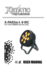
1
A S S E M B L Y
P R O C E D U R E
Chapter
Assembly Procedure
Please follow the information provided in this section to perform
the complete assembly procedure of the notebook. Be sure to
use proper tools described before.
After you have completed the previous chapter of complete disassembly, please follow
this chapter to assemble the notebook back together. This chapter describes the
procedures of the complete notebook assembly. In addition, in between procedures,
the detailed assembly procedure of individual modules will be provided for your service
needs.
V.01-Change HDD screw Twist force
The assembly procedure consists of the following steps:
•
•
•
•
•
•
•
•
•
•
•
M / B A N D B A S E
M O D U L E
Motherboard & Base Module
TOP Module
BASE unit
Blue tooth and HDD Module
CPU and Memory Module
VGA and CPU Thermal Module
ODD Module
LCD Module
Keyboard Module & Wireless Module
Thermal Door
Battery Module
M/B and Base Module
The illustrations below show how to assemble and install the motherboard module of
the notebook. The module contains the motherboard itself, modem board, speaker
cable, adapter cable, audio board module.
1–1
V.01
A S S E M B L Y
M / B
A S S E M B L Y
P R O C E D U R E
Assembling M/B Module
1. Get modem board then insert modem cable.
2. Install modem board to M/B and fasten 2pcs screws to fix.
M2.0*L3
M2.0*L3
PN: MM20030ICI3
Twist force: 2.0+/-0.2KG/CM
Number 1 cross screwdriver
3. Get HDD cable then install to M/B connector.
1-2
V.01
A S S E M B L Y
P R O C E D U R E
4. Install M/B left side into base at first, carefully to arrange HDD cable, make
sure M/B lie on base unit property.
5. Insert adapter cable to M/B connector.
6.
7.
8.
9.
Insert audio cable to audio board.
Install audio board to BASE.
Insert audio cable to M/B connector.
Fasten screw to fix audio board.
M2.5*L6.5
PN: MS25065I007
Twist force: 2.5+/-0.2KG/CM
Number 1 cross screwdriver
1-3
V.01
A S S E M B L Y
P R O C E D U R E
M2.5*L6.5
10. Use a electric type to fix audio cable.
T O P
M O D U L E
TOP Module
The illustrations below show how to install the TOP module into the notebook.
T O P
A S S E M B L Y
Assembling TOP Module
1. Get the TOP install to Base then press the hook of Top and Base.
1-4
V.01
A S S E M B L Y
P R O C E D U R E
2. Install the TP cable to M/B connector.
3. Fasten 3pcs screws to fix TOP.
M2.5*L3
PN: MS25030I057
Twist force: 2.5+/-0.2KG/CM
Number 1 cross screwdriver
4. Fasten 2pcs screws to fix TOP.
M2.5*L6.5
PN: MS25065I007
Twist force: 2.5+/-0.2KG/CM
Number 1 cross screwdriver
M2.5*L3
M2.5*L6.5
5. Turn off the Base unit then put it on worktable.
B A S E
U N I T
B A S U
U N I T
S C R E W
Base unit
The illustrations below showed how to install the screw into the notebook.
Assembling Base screw
1. Fasten 13pcs screws to fix BASE.
M2.5*L6.5
PN: MS25065I007
Twist force: 2.5+/-0.2KG/CM
Number 1 cross screwdriver
1-5
V.01
A S S E M B L Y
P R O C E D U R E
M2.5*L6.5
B L U E
A N D
T O O T H
H D D
M O D U L E
B L U E
T O O T H
M O D U L E
A S S E M B L Y
Blue Tooth and HDD Module
The below illustrations showed how to install the Blue Tooth and HDD module
into the notebook.
Assembling Blue Tooth Module
1. Get blue tooth cable then insert to blue tooth.
2. Insert blue tooth cable to audio board connector then install blue tooth module to
BASE unit and press down blue tooth to make sure the hook locked.
LOCK
H D D
M O D U L E
A S S E M B L Y
Assembling HDD Module
1. Fasten 4 screws to fix HDD BKT with HDD.
M3*L3.5
PN: MS30035I354
Twist force: 3.2+/-0.2KG/CM
Number 1 cross screwdriver
1-6
V.01
A S S E M B L Y
P R O C E D U R E
M3*L3.5
2. Insert the HDD cable to HDD module then install HDD module to base unit.
3. Install the HDD Door to Base unit then fasten 2pcs accessory screws to fix.
Twist force: 2.5+/-0.2KG/CM
Number 1 cross screwdriver
C P U
M E M O R Y
B L U E
C P U
T O O T H
M O D U L E
A S S E M B L Y
CPU & Memory & Blue Tooth Module
The illustrations below showed how to install the CPU and memory module into the
notebook.
Assembling CPU Module
1. Use the CPU vacuum to “suck up” the CPU and place on CPU socket properly.
2. To lock CPU with “—”screwdriver and follow the arrow direction.
1-7
V.01
A S S E M B L Y
M E M O R Y
M O D U L E
A S S E M B L Y
V G A
A N D
C P U
T H E R M A L
V G A
T H E R M A L
A S S E M B L Y
P R O C E D U R E
Assembling Memory Module
Insert RAM at the same 45° angles and press down until it clicks into the latches.
VGA and CPU Thermal Module
The illustrations below showed how to install the VGA and CPU thermal module
into the notebook.
Assembling VGA Thermal Module
1. Get VGA Thermal install to Base unit then fasten 3pcs accessory screws to fix.
Twist force:
2.5+/-0.2KG/CM
Number 1 cross screwdriver
1-8
V.01
A S S E M B L Y
C P U
T H E R M A L
A S S E M B L Y
P R O C E D U R E
Assembling CPU Thermal Module
1. Get CPU thermal install to Base unit then fasten 3pcs accessory screws to fix.
Twist force: 3.0+/-0.2KG/CM
Number 1 cross screwdriver
2. Install FAN cable to FAN connector.
O D D
M O D U L E
ODD Module
The illustrations below showed how to install the ODD module into the notebook.
O D D
M O D U L E
A S S E M B L Y
Assembling ODD Module
1. Get ODD BKT install ODD, fasten 2 screws to fix.
M2.0*L3
PN: MM20030ICI3
Twist force: 1.5+/-0.2KG/CM
Number 1 cross screwdriver
2. Get ODD bezels install to ODD.
M2*L3
3. Install ODD module to Base unit.
4. Fasten 1pcs screw to fix.
M2.5*L16
PN: MS25065I007
Twist force: 2.5+/-0.2KG/CM
Number 1 cross screwdriver
1-9
V.01
A S S E M B L Y
P R O C E D U R E
M2.5*L6.5
L C D
M O D U L E
L C D
M O D U L E
A S S E M B L Y
LCD Module
The illustrations below showed how to install the LCD module into the notebook.
Assembling LCD Module
1. Get LCD to remove ESD bag then check LCD appearance.
2. Insert LCD cable into LCD connector.
3. Remove the Mylar of adhesive and paste LCD cable on LCD.
4. Fasten 4pcs screws on the left and right LCD BKT.
M2.0*L3
PN: MM20030ICI3
Twist force:
2.0+/-0.2KG/CM
Number 1 cross screwdriver
1 - 10
V.01
A S S E M B L Y
P R O C E D U R E
M2*L3
5. Get the LCD cover then check the appearance.
6. Get the LCD module and put into LCD cover then install the camera.
7. Assembly left and right hinge cap.
1 - 11
V.01
A S S E M B L Y
P R O C E D U R E
8. Get inverter and remove Mylar of adhesive then insert cable.
9. Arrange inverter into LCD cover.
10. Fasten 4pcs screws to fix LCD module on LCD cover.
M2.5*L5
M2.5*L5
PN: MM25050ICI6
Twist force: 2.5+/-0.2KG/CM
Number 1 cross screwdriver
11. Take LCD bezel to combine with LCD module and press down all edges to snap
the front bezel and LCD cover together, and then fasten 4pcs screws on LCD
Module.
M2.5*L6.5
PN: MS25065I007
Twist force: 2.5+/-0.2KG/CM
Number 1 cross screwdriver
1 - 12
V.01
A S S E M B L Y
P R O C E D U R E
M2.5*L6.5
L C D
T O
M O D U L E
B A S E
U N I T
Installing LCD Module to Base Unit.
1. Get the LCD module install to Base unit; lock left and right hinge cap.
2. Fasten 2 screws on LCD hinge to fix.
M2.5*L6.5
PN: MS25065I007
Twist force: 3.5+/-0.2KG/CM
Number 1 cross screwdriver
M2.5*L6.5
1 - 13
V.01
A S S E M B L Y
P R O C E D U R E
M2.5*L3
3. Insert LCD cable to M/B connector.
4. Arrange antenna.
5. Turn over the Base unit then fasten 2 screws on LCD hinge.
M2.5*L6.5
PN: MS25065I007
Twist force: 3.5+/-0.2KG/CM
Number 1 cross screwdriver
M2.5*L6.5
K / B \ K / B
C O V E R \ W I R E L E S S
K / B
M O D U L E
A S S E M B L Y
K/B Module & Wireless Module
The illustrations below showed how to install the K/B Module & Wireless module
into the notebook.
Installing K/B Module.
1. Install the power cable to power board then lock.
2. Install the power cable to M/B connector then lock.
1 - 14
V.01
A S S E M B L Y
P R O C E D U R E
3. Put power board into TOP.
4. Put keyboard on TOP.
5. Get K/B the install to system.
6. Assembly K/B Cover.
3
1
2
1 - 15
V.01
A S S E M B L Y
P R O C E D U R E
7. Close the LCD module and turn over notebook.
8. Fasten 4pcs screws to fix power board and K/B cover.
M2.5*L3
PN: MS25030I057
Twist force: 2.0+/-0.2KG/CM
Number 1 cross screwdriver
M2.5*L6.5
M2.5*L3
9. Fasten 1pcs screw to fix keyboard.
M2.5*L6.5
PN: MS25065I007
Twist force: 2.0+/-0.2KG/CM
Number 1 cross screwdriver
W I R E L E S S
M O D U L E
A S S E M B L Y
Installing Wireless Module.
1. Install wireless card into Mini-PCI slot then fasten 1pcs screw to fix.
M2.5*L3
PN: MS25030I057
Twist force: 2.5+/-0.2KG/CM
Number 1 cross screwdriver
1 - 16
V.01
A S S E M B L Y
P R O C E D U R E
M2.5*L3
2. Connect the antenna cable and wireless card.
3. Install Mini-PCI door and fasten 1pcs accessory screw to fix.
Twist force: 2.5+/-0.2KG/CM
Number 1 cross screwdriver
T H E R M A L
D O O R
A S S E M B L Y
T H E R M A L
D O O R
A S S E M B L Y
Thermal Door
The illustrations below showed how to install Thermal door into the notebook.
Assembly Thermal Door.
Get Thermal Door install to the Base unit then fasten the 2pcs accessory screws.
Twist force: 2.5+/-0.2KG/CM
Number 1 cross screwdriver
1 - 17
V.01
A S S E M B L Y
B A T T E R Y
M O C U L E
B A T T E R Y
M O D U L E
P R O C E D U R E
Battery Module
The illustrations below showed how to install the Battery module into the
notebook.
Assembly Battery Module.
Install battery pack into battery slot properly then lock.
A S S E M B L Y
Disassembly Reminding
First needs remove the battery module.
Release K/B cover、Power board and Keyboard screws, disassembly the
K/B Cover carefully, must pay attachment damage the hook of K/B
Cover.
B A T T E R Y
M O D U L E
B A T T E R Y
M O D U L E
D I S A S S E M B L Y
Battery module
The illustrations below show how to remove the Battery module from the notebook.
Battery Module Disassembly
1. Turn over the notebook, Unlock one latch and push another latch (No.2), remove
the battery pack(No.3)
2
1
3
K E Y B O A R D
M O D U L E
K / B
C O V E R
D I S A S S E M B L Y
. Keyboard Module
The illustrations below show how to remove the K/B cover and keyboard plate from
the notebook.
Disassembling K/B Cover Module
1. Release K/B cover 、Power board and Keyboard screws.
1 - 18
V.01
A S S E M B L Y
P R O C E D U R E
Twist force: 2.0+/-0.2KG/CM
Number 1 cross screwdriver
2. Turn over notebook and open the LCD module.
3. Pick up the K/B cover from left sides then separate it.
Thank!
1 - 19
V.01