1
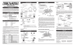
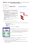
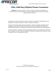
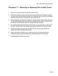
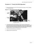
RBK 815 Recumbent Cycle
Procedure 7.1 - Replacing a Cover
Cover Removal
1.
Remove two screws, one each side, from the front of the top cover. Remove the
top cover. See Diagram 7.1.
Diagram 7.1 - RBK 815 Covers
Top Cover
Left Side Cover
Rear Cover
2.
Remove three screws from the right side cover, remove the left side cover.
3.
Remove three screws from the left side cover, remove the right side cover
4.
Remove three screws, one each side and one in the rear, from the rear cover.
Remove the rear cover
5.
Remove three screws from the seat frame cover. Remove the seat frame cover.
See Diagram 7.2.
Diagram 7.2 - RBK 815 Covers
Kick plate
Seat Frame Cover
Page 33
RBK 815 Recumbent Cycle
6.
Slide the kick plate forward and remove it from the frame.
Cover Replacement
7.
Set the kick plate in its mounting position on the frame and slide it back into
place.
8.
Set the seat frame cover in its mounting position and fasten it with the screws
removed in step 5, torque to 20 inch pounds.
9.
Set the rear cover in its mounting position and fasten it with the three screws
removed in step 4, torque to 20 inch pounds.
10. Set the right frame cover in its mounting position and fasten it with the screws
removed in step 2, torque to 20 inch pounds.
11.
Slide the connector assembly into the slot in the lower front portion of the right
side cover. See Diagram 7.3.
Diagram 7.3 - CAT5, Coax Connector Assembly
12. Set the left side cover in its mounting position, with the connector assembly in its
slot in the left side cover and fasten it with the screws removed in step 3, torque
to 20 inch pounds.
13. Set the top cover in its mounting position and fasten it with the screws removed
in step 1, torque to 20 inch pounds.
Page 34
RBK 815 Recumbent Cycle
Procedure 7.2 - Replacing a Primary Belt
1.
Remove the top, rear, left and right covers per procedure 7.1.
2.
Loosen but do not remove the idler pulley mounting nut.
3.
Loosen the primary belt tension adjustment bolt to remove tension from the
primary belt. See Diagram 7.4.
4.
Remove and discard the primary belt.
Diagram 7.4 - Primary Belt
Primary Belt
Tension Adj. Bolt
Idler Pulley
Input Pulley
Secondary
Sheave
Idler Pulley
Mounting Nut
Primary Belt
5.
Place the replacement primary belt in its mounting position around the input
pulley, under the idler pulley and around the secondary sheave.
6.
Tension the primary belt per Procedure 5.1. When the belt tension is correct,
torque the idler pulley mounting nut to 120 inch pounds (10 foot pounds).
7.
Replace the covers per procedure 7.1.
Page 35
RBK 815 Recumbent Cycle
Procedure 7.3 - Replacing a Secondary Belt
1.
Remove the top, rear, left and right covers per procedure 7.1.
2.
Loosen but do not remove the four generator mounting bolts.
3.
Remove tension from the secondary belt by loosening the secondary belt
adjustment bolt mounted on the generator. See Diagram 7.5.
Diagram 7.5 - Secondary Belt
Secondary Pulley
Generator
Secondary Belt
Secondary Belt
Adj. Bolt
Generator
Mounting Bolt
Generator Pulley
Generator
Mounting Bolt
4.
Lift the generator, it will pivot on the rear mounting bolts, to remove the
generator’s weight from the secondary belt then remove and discard the
secondary belt.
5.
Lift the generator and place the replacement secondary belt in its mounting
position around the generator and secondary pulleys.
6.
Tension the secondary belt per Procedure 5.2.
7.
Torque the four generator mounting bolts to 100 inch pounds. Recheck the belt
tension, if it is no longer correct, slightly loosen the four generator mounting bolts
and return to step 6.
8.
Replace the covers per Procedure 7.1.
Page 36
RBK 815 Recumbent Cycle
Procedure 7.4 - Replacing a Crankarm
1.
Using an 15mm open end wrench, remove the pedal from the crankarm being
replaced.
2.
A Park Tool CCP-22 crankarm puller will be used to remove the crankarms.
Diagram 7.6 - Park Tool CCP-22 Crankarm Puller
3.
Using an 8mm allen wrench, remove the crankarm mounting bolt.
4.
Remove the nut from the crankarm puller. Thread the nut fully into the crankarm,
until the bottoms out. See Diagram 7.7.
Note: If the nut is not fully threaded into the crankarms, the crankarm’s threads may
be destroyed when the crankarm is removed.
5.
Thread the crankarm puller into the nut removed from the crankarm puller. See
Diagram 7.7. When the crankarm puller tightens in the crankarm, continue
rotating the crankarm tool clockwise until the crankarm is removed.
Diagram 7.7 - Crankarm with Crankarm Puller
Step 4
Step 3
6.
The right hand crankarm has a pin on the rear that fits into the input pulley. The
left hand crankarm does not have a pin on the rear.
7.
Set the replacement crankarm in its mounting position, ensuring that the pin
(right hand crankarm only) on the crankarm is inserted in its mating hole in the
input pulley.
Page 37
RBK 815 Recumbent Cycle
8.
Thread the crankarm mounting bolt, removed in step 2 into the crankarm until it
is finger tight. Torque the crankarm bolt to 360 inch pounds (30 foot pounds).
9.
The right hand pedal threads onto the crankarm in a normal (clockwise) direction,
the left hand crankarm is reverse (counter-clockwise) threaded.
10. Install the pedal, removed in step 1, on the replacement crankarm and torque it to
800 inch pounds (67 foot pounds).
11.
Pedal the bike for 1 minute and then re-torque left and right crankarms to the
specification indicated in steps 8 and 9.
Page 38
RBK 815 Recumbent Cycle
Procedure 7.5 - Replacing the Input Pulley
1.
Remove the top, rear, left and right covers per procedure 7.1.
2.
Remove the right crankarm per Procedure 7.4.
3.
Loosen, but do not remove the idler pulley mounting nut.
4.
Remove tension from the primary belt by turning the primary belt tension
adjustment bolt counter-clockwise. See Diagram 7.4.
5.
Remove the primary belt.
6.
Remove the retaining nut from the center of the input pulley while holding the
opposite end of the input axle with an open end wrench, turning clockwise. See
Diagram 7.8.
Diagram 7.8 - Input Pulley
Input Pulley
Retaining Nut
7.
Remove the input pulley and discard.
8.
Slide the replacement input pulley onto the input axle, ensuring that the spacer is
still in place behind the input pulley.
9.
Thread the retaining nut, removed in step 6. onto to the input axle, finger tight
only at this time.
10. Place the primary belt in its mounting position around the input pulley, under the
idler pulley and around the secondary sheave.
11.
Replace the right crankarm per procedure 7.4, steps 6 to 8.
12. Using the thin 1-1/8 inch end wrench, reach behind the crankarm and securely
tighten (counter-clockwise) the input pulley’s retaining nut.
13. Tension the primary belt per procedure 5.1.
Page 39
RBK 815 Recumbent Cycle
14. Replace the covers per Procedure 7.1.
Page 40
RBK 815 Recumbent Cycle
Procedure 7.6 - Replacing the Input Axle Assembly
1.
Remove the top, rear, left and right covers per procedure 7.1.
2.
Remove both crankarms per Procedure 7.4.
3.
Loosen, but do not remove the idler pulley mounting nut.
4.
Remove tension from the primary belt by turning the primary belt tension
adjustment bolt counter-clockwise. See Diagram 7.4.
5.
Remove the primary belt.
6.
Remove the retaining nut from the center of the input pulley.
7.
Slide the input pulley off of the input axle assembly and remove spacer.
8.
Remove the two small screws and washers that retain the input axle assembly.
See Diagram 7.9.
Diagram 7.9 - Input Axle Assembly
Axle Retaining Screw
9.
Slide the input axle assembly out of the frame and discard.
10. Slide the replacement input axle assembly into its mounting position in the frame.
11.
Slide spacer onto axle assembly.
12. Fasten the input axle assembly with the screws and washers remove in step 8.
13. Slide the input pulley, removed in step 7, onto the input axle assembly. Thread the
nut, removed in step 6, onto the input axle assembly. Finger tight only at this
time.
14. Place the primary belt in its mounting position around the input pulley, under the
idler pulley and around the secondary sheave.
15. Replace the right crankarm per procedure 7.4, steps 6 to 8.
16. Using the thin 1-1/8 inch end wrench, reach behind the crankarm and securely
Page 41
RBK 815 Recumbent Cycle
tighten (counter-clockwise) the input pulley’s retaining nut.
17. Tension the primary belt per Procedure 5.1.
18. Replace the left crankarm per procedure 7.4.
19. Replace the covers per Procedure 7.1.
Page 42
RBK 815 Recumbent Cycle
Procedure 7.7 - Replacing the Idler Pulley
1.
Remove the top, rear, left and right covers per procedure 7.1.
2.
Loosen, but do not remove the idler pulley mounting nut.
3.
Remove tension from the primary belt by turning the primary belt tension
adjustment bolt counter-clockwise. See Diagram 7.4.
4.
Remove the primary belt.
5.
Remove the idler pulley by removing the idler pulley mounting nut. Discard the
idler pulley.
6.
Mount the replacement idler pulley using the nut removed in step 5. The idler
pulley mounting nut should only be finger tight at this time.
7.
Replace the primary belt and tension the primary belt per Procedure 5.1.
8.
Torque the idler pulley mounting nut to 120 inch pounds (10 foot pounds).
9.
Replace the covers per Procedure 7.1.
Page 43
RBK 815 Recumbent Cycle
Procedure 7.8 - Replacing the Secondary Sheave
1.
Remove the top, rear, left and right covers per procedure 7.1.
2.
Loosen, but do not remove the idler pulley mounting nut.
3.
Remove tension from the primary belt by turning the primary belt tension
adjustment bolt counter-clockwise. See Diagram 7.4.
4.
Remove the primary belt.
5.
Insert a 1/4 inch allen wrench into the primary pulley, the allen wrench will keep
the secondary axle from turning and allow the secondary sheave to be removed.
6.
While holding the secondary axle with a 3/8 inch allen wrench, use the 20030-119
sheave removal tool and a 1/2 inch drive socket wrench to remove the secondary
sheave. See Diagram 7.10.
Diagram 7.10 - Secondary Sheave Removal
20030-119
Sheave Tool
7.
Thread the replacement sheave onto the secondary axle assembly. Using the
allen wrench, 20030-119 sheave tool and socket wrench securely tighten the
secondary sheave.
8.
Replace the primary belt and tension the primary belt per Procedure 5.1.
9.
Torque the idler pulley mounting bolt to 120 inch pounds (10 foot pounds).
10. Replace the covers per Procedure 7.1.
Page 44
RBK 815 Recumbent Cycle
Procedure 7.9 - Replacing the Secondary Pulley
1.
Remove the top, rear, left and right covers per procedure 7.1.
2.
Loosen, but do not remove the generator screws and tension bracket mounting
bolt, thread the tension adjustment bolt counter-clockwise to remove tension
from the secondary belt. See Diagram 7.13.
3.
Remove the retaining clip from the secondary axle. See Diagram 7.11.
Diagram 7.11 - Secondary Pulley
Secondary Pulley
Retaining Clip
Plastic Washer
4.
Remove the plastic washer and the secondary pulley. Discard the secondary
pulley.
5.
Slide the replacement secondary pulley onto the secondary axle. Slide the plastic
washer, removed in step 4 onto the secondary axle. fasten the secondary pulley
with the retaining clip removed in step 4.
6.
Replace the secondary belt and tension it per Procedure 5.2.
7.
Replace the covers per procedure 7.1.
Page 45
RBK 815 Recumbent Cycle
Procedure 7.10 - Replacing the Secondary Axle Assembly
1.
Remove the top, rear, left and right covers per procedure 7.1.
2.
Loosen, but do not remove the idler pulley mounting nut.
3.
Remove tension from the primary belt by turning the primary belt tension
adjustment bolt counter-clockwise. See Diagram 7.4.
4.
Loosen, but do not remove the generator screws and tension bracket mounting
bolt, thread the tension adjustment bolt counter-clockwise to remove tension
from the secondary belt. See Diagram 7.13.
5.
Remove the secondary sheave per Procedure 7.8.
6.
Remove the secondary pulley per Procedure 7.9.
7.
Remove a second plastic washer from the secondary pulley side of the secondary
axle.
8.
Remove a retaining clip and from the secondary sheave side of the secondary
axle.
9.
Remove a large retaining clip from the secondary pulley side of the secondary
axle.
10. Remove the secondary axle from the frame and discard.
11.
Slide the replacement secondary axle into its mounting position in the frame.
Fasten the secondary axle with the large retaining clip removed in step 9. Inspect
the retaining clip to insure that it is securely snapped in.
12. Replace the retaining clip removed in step 8.
13. Slide a plastic washer, removed in step 7, onto the secondary pulley side of the
secondary axle.
14. Replace the secondary pulley per Procedure 7.9.
15. Replace the secondary sheave per procedure 7.8.
16. Tension the secondary belt per Procedure 5.2.
17. Tension the primary belt per Procedure 5.1.
18. Replace the covers per Procedure 7.1.
Page 46
RBK 815 Recumbent Cycle
Procedure 7.11 - Replacing a Generator
1.
Remove the top, rear, left and right covers per procedure 7.1.
2.
Disconnect the two generator cables from the lower PCA. The cables are
connected to M1, M2 and M3, M4, M5 on the lower PCA. See Diagram 6.1. Remove
the generator clips from their cable retaining clips. See Diagram 7.13.
3.
Remove the tension adjustment bolt and washer, remove the tension bracket
mounting bolt, washer and tension bracket. See Diagram 7.13.
4.
Loosen the three generator mounting bolts, one front and two rear.
5.
Lift the generator, it will pivot on the rear mounting bolts, to remove the
generator’s weight from the secondary belt then remove the secondary belt.
Diagram 7.13 - Generator Tension Adjustment Hardware
Tension Adjustment
Bolt & Washer
Tension Bracket
Bolt
Tension Bracket
Cable Retaining
Clip
6.
Remove three generator mounting bolts, one front and two rear.
7.
Remove and discard the generator.
8.
Set the replacement generator in its mounting position. Hand start and hand
tighten the three generator mounting bolts removed in step 6.
9.
Place the tension adjustment bolt and washer in its mounting position on the
replacement generator.
10. Thread the adjustment bolt into the tension bracket. Fasten the tension bracket
with the bolt and washer removed in step 3. The bolt should only be hand tight.
11.
Replace the secondary belt.
12. Tension the secondary belt per Procedure 5.2.
13. Torque the three generator mounting bolts and the tension bracket bolt to 100
Page 47
RBK 815 Recumbent Cycle
inch pounds.
14. Reconnect the two generator cables, removed in step 2 to the lower PCA.
Connect the two red magnet wires to terminals M1 & M2, the order does not
matter. Connect the red generator wire to M3, the white generator wire to M4
and the black generator wire to M5. Check cable routing to insure cables will not
rub on generator. See Diagram 7.14.
15. Replace the covers per Procedure 7.1.
Page 48
RBK 815 Recumbent Cycle
Procedure 7.12 - Replacing a Battery
1.
Remove the top rear, top main and left side covers per Procedure 7.1.
2.
The battery is held in place by the covers.
3.
Remove the red and black wires from the battery.
4.
Remove the battery and properly dispose of the battery.
5.
Set the battery on the frame near its mounting position with the positive terminal
(red dot) to the left.
6.
If the battery does not have a wire clip on the left side, positive side of the
battery, add one at this time.
7.
Connect the black wire to the battery’s negative terminal and the red wire to the
battery’s positive (red dot) terminal.
8.
Route the cables to left side and run them through the wire clip. Ensure cable is
not run near the primary pulley.
9.
Slide the battery in into the battery pocket in the right hand cover, the battery
must be oriented with its long axis side to side and the wire harness must be run
to left side of the bike. If the battery orientation is incorrect, the covers will not fit.
10. Replace the covers per Procedure 7.1.
Page 49
RBK 815 Recumbent Cycle
Procedure 7.13 - Replacing the Lower PCA
1.
Remove the top, rear, left and right covers per procedure 7.1.
2.
Disconnect all of the wires from the lower PCA.
3.
Remove the four screws that fasten the lower PCA. Remove and discard the
lower PCA.
4.
Set the replacement lower PCA in its mounting position and fasten it with the four
screws removed in step 3.
5.
Reconnect the wiring to the lower PCA as follows: two red generator magnet
wires to M1, M2; red generator wire to M3, white generator wire to M4, black
generator wire to M5; red battery wire to M6, Black battery wire to M7; the data
cable to connector J2. See Diagram 7.14.
Diagram 7.14 - Lower PCA
Black Battery Wire
Red Battery Wire
Data Cable
Generator
Magnet Wires
6.
Red, White Black
Generator Wires
Replace the covers per Procedure 7.1.
Page 50
RBK 815 Recumbent Cycle
Procedure 7.14 - Replacing a Display Front Panel, Upper
PCA, Metrics PCA or HR PCA
The keyboard is part of the display front panel front panel. If the keyboard is not
functioning properly, replace the display front panel front panel.
Removing the display Front Panel
1.
Remove the top rear, top main and right side covers and disconnect the red
battery wire from the battery.
WARNING
Before continuing with this procedure, review the Warning and Caution statements
listed in Section One, Things You Should Know.
2.
Attach the anti-static wrist strap to your arm, then connect the ground wire of the
wrist strap to the units frame.
3.
Remove the four screws that secure the display’s rear cover.
4.
Disconnect the interconnect cable and heart rate cable from the upper PCA.
Diagram 7.15 - Display, with Rear Cover Removed
Snap
Interconnect
Cable
Snap
Heart Rate
Cable
Snap
HR PCA
5.
Starting from the top and working downward, unsnap the display front panel
from the display. There are six snaps retaining the display front panel. See
Diagram 7.15.
6.
Proceed to the upper PCA, metrics PCA, HR PCA, D-Pad or display front panel
Page 51
RBK 815 Recumbent Cycle
replacement procedure as required.
Removing and Replacing the Upper PCA
7.
Carefully disconnect the keyboard cable from the upper PCA. See Diagram 6.3.
8.
Disconnect the cables from the metrics PCA and the and the D-pad PCA. See
Diagram 6.3.
9.
Unsnap the upper PCA from the display front panel.
Note:
Package the upper PCA in an anti-static bag and document the problem as described
in Procedure 3.4, Documenting Software Problems.
10. Position the upper PCA at its mounting location on the display front panel and
snap it into place (refer to Diagram 6.3).
11.
Reconnect the keyboard cable, D-pad cable and metrics PCA cable to the upper
PCA. See Diagram 6.3.
12. Skip to step 33.
Replacing a Metrics PCA
13. Disconnect the metrics cable from the metrics PCA. See Diagram 6.3.
14. Unsnap the metrics PCA from the display front panel and discard.
15. Place the replacement metrics PCA in its mounting position on the display front
panel and snap it into place.
16. Reconnect the metrics cable to the metrics PCA.
17. Skip to step 33.
Replacing a HR PCA
18. Disconnect the HR PCA to UPCA cable and HR PCA to hand grips cable from the
HR PCA. See Diagram 7.16
19. Unsnap the HR PCA from the display front panel and discard.
20. Place the replacement HR PCA in its mounting position on the display front panel
and snap it into place.
21. Reconnect the HR PCA to UPCA cable and HR PCA to hand grips cable to the HR
PCA.
22. Skip to step 33.
Page 52
RBK 815 Recumbent Cycle
Replacing a D-Pad Assembly
23. Disconnect the D-pad cable from the D-pad assembly. See Diagram 6.3.
24. Unsnap the D-pad assembly from the display front panel and discard.
25. Place the replacement D-pad assembly in its mounting position on the display
front panel and snap it into place.
26. Reconnect the D-pad cable to the D-pad assembly
27. Skip to step 33.
Replacing a Display Front Panel
28. Remove the keypad cable from the upper PCA. Remove the metrics cable from
the upper PCA and metrics PCA. Remove the D-pad cable from the upper PCA
and D-pad assembly. See Diagram 6.3.
29. Remove the upper PCA, metrics PCA, and D-pad assembly from the display front
panel as described in the above procedures.
30. Snap the upper PCA, metrics PCA and D-pad assembly onto the replacement
display front panel.
31. Reconnect the keypad cable to the upper PCA. Reconnect the metrics cable to
the upper PCA and metrics PCA. Reconnect the D-pad cable to the upper PCA
and the D-pad assembly.
32. Starting from the bottom and working upward, snap the display front panel onto
the display back panel.
33. Reconnect the interconnect and heart rate cables to the upper PCA.
34. Remove the ground wire of the wrist strap from the bicycle frame, then remove
the wrist strap from your arm.
35. Position the display’s rear cover on the display back panel. Replace and tighten
the display mounting screws.
36. Replace the red battery wire removed in step 1.
37. Replace the covers per Procedure 7.1.
38. Check unit operation as described in Section Four.
Page 53
RBK 815 Recumbent Cycle
Procedure 7.15 - Replacing All or Part of a Seat Carriage
Removing the Seat Carriage
1.
There is a heart rate cable that connects the heart rate hand grips in the seat
carriage to the hear rate cable in the seat rail. Care must be taken when removing
the seat carriage to avoid damaging the heart rate cables.
2.
Move the seat carriage to its most forward position. Carefully unsnap the water
bottle holder from the rear of the seat carriage.
3.
Remove the two screws that fasten the end cap in the seat rail. remove the end
cap. Slide the seat stop out of the seat rail. See Diagram 7.16.
Diagram 7.16 - Seat Rail End Cap and Seat Stop
Water
Bottle
Holder
End Cap
Seat Stop
4.
Remove the cable cover and disconnect the heart rate cables. See Diagram 7.17.
Page 54