1
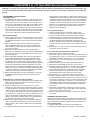
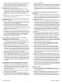
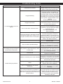
SERVICE INSTRUCTIONS FOR
3M™ 12,000 RPM 3 in. (77 mm)
RANDOM ORBITAL SANDERS
3M™ Overhaul Service Kit
The part number 20346, 3M™ Overhaul Service Kit, contains all the replacement parts that naturally
wear over time and a straightforward manual to make servicing an 3M™ sander simple. Overhauling the
Random Orbital Sander can be made even easier with the use of the above Service Tools. The Service
Tools also reduce the chance of improper assembly.
Part Number
34-8700-5192-6
Description
Qty
3MA0040
EXTERNAL RETAINING RING
1
3MA0021
BEARING - 2 SHIELDS
1
3MB0005
ROTOR
1
3MA0010
VANE
5
3MA0041
WOODRUFF KEY
1
3MA0042
O-RING
1
3MA0019
BEARING - 2 SHIELDS
1
3MA0162
BEARING - NO SEAL/SHIELDS
1
3MA0196
SPACER
1
3MA0161
BEARING - 1 SEAL
1
3MA0039
INTERNAL RETAINING RING
1
3MA0068
MUFFLER INSERT
1
3MA0062
INTERNAL MUFFLER
1
3MA0009
VALVE SEAT
1
3MA0007
VALVE
1
3MA0014
VALVE SPRING
1
3MA0043
O-RING
1
3MA0008
VALVE STEM ASSEMBLY
1
3MA0166
MUFFLER HOUSING
1
3MA1416
INSTRUCTIONS FOR 3 in. ROS OVERHAUL SERVICE KIT
1
Revision 10/03/07
12,000 RPM 3 in. (77 mm) ROS Service Instructions
NOTICE: To receive any expressed or implied warranty, the tool must be repaired by an authorized Service Center. The
3 in. (77 mm) Random Orbital Sander Service Instructions section provided is for use after completion of the warranty
period.
DISASSEMBLY INSTRUCTIONS
Changing Grips:
1. The Grip has two “tabs” that wrap around the body of the
sander under the inlet and exhaust. Use a small screwdriver to pick out one of the “tabs” of the Grip, then continue to go underneath the Grip with the screwdriver and
pry the Grip off the sander. To install a new Grip, hold
the Grip by the tabs making them face outward, align the
Grip and slide it under the Throttle Lever then press the
Grip down until it seats onto the top of the sander. Make
sure the two “tabs” seat under the inlet and exhaust.
Motor Disassembly:
1. Lightly secure the tool in a vise using the T-7 Service Collar or padded jaws. Use a 17 mm Pad Wrench to secure
the Spindle and spin the Pad counter clock-wise off the
spindle.
2. Remove the Lock Ring with the T-6 Motor Lock Ring
Wrench/Spindle Puller Tool. The motor assembly can
now be lifted out of the Housing. Remove the O-Ring
from the Lock Ring.
3. Secure the motor assembly by clamping the Shaft
Balancer in a padded jaw vise and remove the Retaining
Ring from the end of the Shaft Balancer and the O-ring
from the Cylinder.
4. Remove the Rear Endplate. This may require supporting the Rear Endplate with a bearing separator. Use
a light press force to push the Shaft Balancer through
the Bearing. Then remove the Cylinder, Vanes and the
Rotor. Remove the Key from the Shaft Balancer. Support
the Front Endplate with a bearing separator and use a
light press force to push the Shaft Balancer through the
bearing. It may be necessary to remove the Bearing with
a bearing separator if it came out of the Front Endplate
and stuck to the shaft of the Shaft Balancer.
5. Remove the Bearing(s) from the Endplates by using the
T-8 Endplate Bearing Removal Tool to press out the
Bearings.
Shaft Balancer and Spindle Disassembly:
1. Grip the shaft end of the Shaft Balancer in a padded vise.
With a thin screwdriver pick out the slotted end of the
Retaining Ring and peel out.
2. Screw the female end of the T-11 5/16-24 to 1/4-20
Adapter into the male end of the Service Wrench. Screw
the Service Wrench assembly into the Spindle Assembly
until hand tight. Apply a gentle heat from a propane torch
or hot air gun to the large end of the Shaft Balancer until
it is about 212° F (100° C) to soften the adhesive. Do not
over heat. Remove the Spindle Assembly by using the
Slider to give sharp outward blows to the Spindle. Allow
the parts to cool so they are safe to handle.
3. Remove the Retaining Ring from the Spindle Assembly.
Use a small Bearing Separator to remove the Bearing,
Shim, Bearing, Shim and the Washer from the Spindle
Assembly.
4. The bearing shield components are held in place by the
34-8700-5192-6
light press fit of the Retainer. These components can be
damaged during removal and may need to be replaced if
removed. To remove the Retainer, use an O-ring pick or
a #8 sheet metal screw to grip and pull out the Retainer.
Remove the Valve and Filter from the bore in the Shaft
Balancer. If the Retainer and Valve were not damaged,
they can be reused. However, the Filter should be
replaced on re-assembly.
Housing Disassembly:
1. For Non-Vacuum (NV) and Central Vacuum (CV)
machines follow steps A – B below (unless otherwise
noted). For Self Generated Vacuum (SGV) machines
disregard steps A – E and move onto Step G below.
A. Unscrew the Muffler Housing from the Housing. Remove
the Bronze Muffler from the Muffler Housing (if applicable). Remove the Muffler from the Muffler Housing.
For NV machines move onto B. For CV machines move
onto C.
B. Remove the 3 in. (77 mm) Non-Vacuum Shroud. For NV
machines move onto step 2.
For Central Vacuum (CV) Exhaust machines:
C. Remove the Screw, Washer and Nut.
D. Remove the Ø ¾ in. (19 mm) CV Swivel Exhaust Assembly (Optional) or the Ø 1 in. (28 mm) CV Swivel Exhaust
Assembly (Standard) from the 3 in. (77 mm) Shroud.
E. Remove the 3 in. (77 mm) Shroud from the Housing.
Move onto step 2.
For Self Generated Vacuum (SGV) Exhaust machines:
F. Unscrew the SGV Retainer with an 8 mm hex key.
G. Remove the Ø 1 in. (28 mm) Hose SGV Swivel Exhaust
Assembly (Standard) or Ø ¾ in. (19 mm) Hose SGV
Swivel Exhaust Assembly (Optional) from the Adapter.
H. Pull the SGV Retainer out of the bore of the Swivel
Exhaust Assembly and remove the two O-Rings.
I. Remove the 3 in. (77 mm) Shroud from the Housing.
2. Place the Speed Control to the midway position and remove the Retaining Ring. NOTE: If the machine is one of
the vacuum models, the vacuum exhaust assembly must
be removed (See section 1 above, for removal) before
the Retaining Ring can be removed with lock ring pliers.
The Speed Control will now pull straight out. Remove
the O-ring.
3. Unscrew the Inlet Bushing Assembly from the Housing.
Remove the Spring, Valve, Valve Seat, Valve Stem and
the O-ring from the Valve Stem.
4. Press out the Spring Pin from the Housing and remove
the Lever.
ASSEMBLY INSTRUCTIONS
NOTE: All assembly must be done with clean dry parts and
all bearings are to be pressed in place by the correct tools
and procedures as outlined by the bearing manufacturers.
Housing Assembly:
1. Install Throttle Lever into Housing with Spring Pin.
2. Lightly grease the O-Ring and place it on the Speed
Revision 10/03/07
Control. Install the Valve Stem and O-ring (cleaned and
lightly greased) and insert the Speed Control into Housing in the midway position. Install Retaining Ring.
CAUTION: Make sure the Retaining Ring is completely
snapped into groove in the Housing.
3. Install the Valve Seat, Valve and the Spring. Coat the
threads of the Inlet Bushing Assembly with 1 or 2 drops
of 3M Rite-Loc TL22 or equivalent non-permanent pipe
thread sealant. Screw the Inlet Bushing Assembly into
the inlet port on the Housing. Torque to 60 in/lbs (6.77
Nm.)
4. For NV and CV machines follow the steps A - C. For SGV
machines follow the steps G - J.
This section is for Central Vacuum (CV) and Non-Vacuum (NV) machines.
A. Place a clean Muffler all-the-way into the chamber of the
Muffler Housing. Press the Bronze Muffler into the bore
of the Muffler Housing (if applicable).
B. Screw the Muffler Housing assembly into the Housing
until hand tight. Use a 21 mm socket/torque wrench
combination to torque the Muffler Housing. Torque to 20
in/lbs (2.25 Nm). For NV machines move onto C. For CV
machines move onto step D.
C. Install the 3 in. (77 mm) Non-Vacuum Shroud onto the
Housing by working the Shroud over and around the bottom of the Housing flanges. Make sure the line up slots
on the Housing and tabs on the Shroud are engaged.
Move onto the “Spindle Bearings, bearing shield and
Shaft Balancer Assembly” Section.
This section continued from Section I for Central
Vacuum (CV) Exhaust machines:
D. Install the 3 in. (77 mm) CV Shroud on to the Housing
by working the shroud over and around the bottom of
the Housing flanges. Make sure the line up slots on the
Housing and tabs on the Shroud are engaged.
E. Slide the inlet end of the Ø ¾ in. (19 mm) CV Swivel
Exhaust Assembly (Optional) or the Ø 1 in. (28 mm) CV
Swivel Exhaust Assembly (Standard) into the exhaust
port of the 3 in. (77 mm) CV Shroud until it hits the stop
on the CV Swivel Exhaust Assembly. Make sure the key
on the CV Swivel Exhaust Assembly bracket is aligned
and engaged with the keyway on the Housing.
F. Place the Washer over the Screw. Thread the screw into
the CV Swivel Exhaust Assembly or Ø 1 in. (28 mm) CV
Swivel Exhaust Assembly (Optional) and Housing until
the end of the screw is flush with the inside surface of
the Housing. Place the Nut into the cavity of the Housing
and thread the screw into the nut until tight. Move onto
the “Spindle, bearing shield and Shaft Balancer Assembly” Section.
For Self Generated Vacuum (SGV) Exhaust machines:
G. Install the 3 in. (77 mm) Shroud onto the Housing by
working the shroud over and around the bottom of the
housing flanges. Make sure the line up slots on the
Housing and tabs on the Shroud are engaged. Slide the
SGV Exhaust Adapter Fitting into the exhaust of the 3 in.
(77 mm) CV Shroud.
H. Lightly grease two O-Rings and place them into the two
grooves in the SGV Retainer.
I. Put the SGV Retainer into the mounting hole of the Ø 1
in. (28 mm) Hose SGV Swivel Exhaust Assembly (Standard) or the Ø ¾ in. (19 mm) Hose SGV Swivel Exhaust
34-8700-5192-6
Assembly (Optional).
J. Slide the Swivel Exhaust Assembly into the SGV Exhaust
Adapter Fitting while at the same time inserting the SGV
Retainer into the sander Housing exhaust port. Screw
the SGV Retainer into the threaded exhaust port on the
Housing with an 8 mm hex key. Torque to 45 in/lbs (5.08
Nm. ).
Spindle Bearings, Bearing Shield and Shaft Balancer
Assembly:
1. Place the T-5A Spindle Bearing Pressing Tool Base onto
a flat, clean surface of a small hand press or equivalent
with the spindle pocket facing upward. Place the Spindle
into the spindle pocket with the shaft facing upwards.
See Figures 1 and 2.
2. Place theWasher on the Spindle shaft with the curve of
the Washer facing out so that the outside diameter of the
Washer will contact the outer diameter of the Bearing
(one seal). Lay the Shim on the shoulder of the Spindle.
Place the Bearing (one seal) on the Spindle with the seal
side toward the Washer. NOTE: Make sure that both the
inner and outer races of the Bearings are supported by
the Bearing Press Tool when pressing them into place.
Press the Bearing onto the shoulder of Spindle using
the T-5B Spindle Bearing Pressing Tool Top as shown in
Figure 2.
3. Place the Shim over the Spindle shaft and onto the face
of the Bearing making sure it is on center. Press the
(no seals/shields) Bearing down using the T-5A Spindle
Bearing Pressing Tool Top, being careful to make sure
the Shim is still centered on the vertical axis of the
Spindle shaft and Bearing. See Figure 3. NOTE: When
the Spindle Assembly is done correctly, the Bearings will
rotate freely but not loosely and the Shim can be moved
but will not slide or move by gravity.
4. Secure the Retaining Ring onto the Spindle Assembly
making sure it is completely snapped into the groove.
Set the Spindle Assembly aside.
5. Take the Filter and center it on the small bore that the
original filter was in before removal. With a small diameter screwdriver or flat end rod, press the Filter into the
bore until it is flat in the bottom of the bore. Place the
Valve into the bore so it is oriented correctly, then press
the Retainer into the bore until it is flush with the bottom
of the bearing bore.
6. Apply a pin head size drop of 3M Rite-Loc TL71 or equivalent to the outside diameter of each of the bearings on
the Spindle Assembly. Spread the drop of bearing locker
around both bearings until distributed evenly. CAUTION:
Only a very small amount of bearing locker is needed to
prevent rotation of the bearing OD. Any excess will make
future removal difficult. Place the Spindle Assembly
into the bore of the Shaft Balancer and secure with the
Retaining Ring. CAUTION: Make sure that the Retaining
Ring is completely snapped into the groove in the Shaft
Balancer. Allow the adhesive to cure.
Motor Assembly:
1. Use the larger end of the T-13 Bearing Press Sleeve to
Press the front Bearing (with 2 Shields) onto the shaft of
the Shaft Balancer.
2. Slide the Front Endplate with the bearing pocket facing
down onto the Motor Shaft. Gently press the Front
Endplate onto the front Bearing using the larger end of
the T-13 Bearing Press Sleeve until the front Bearing is
Revision 10/03/07
Bearing
Press Tool Top
Bearing
Shim
Shim
Washer
Spindle
Press Tool Base
Figure 1
Figure 2
seated in the bearing pocket of the Front Endplate. CAUTION: Only press just enough to seat the bearing into the
pocket. Over-pressing can damage the bearing.
3. Place the Key into the groove on the Shaft Balancer.
Place the Rotor onto the shaft of the Shaft Balancer,
making sure that it is a tight slip fit.
4. Oil the five Vanes with a quality pneumatic tool oil and
place in the slots in the Rotor. Place the Cylinder Assembly over the Rotor with the shorter end of the Spring
Pin engaging the blind hole in the Front Endplate. NOTE:
The Spring Pin must project .060 in. (1.5 mm) above the
flanged side of the Cylinder.
5. Press fit the rear (2) Bearing (2 shields) into the Rear
Endplate with the T-1B Bearing Press Tool. Make sure
the T 1B Press Tool is centered on the O.D. of the outer
race. Lightly press fit the Rear Endplate and Bearing
Assembly over the Shaft Balancer using the small end
of the T-13 Bearing Press Sleeve. The sleeve should
press only the inner race of the bearing. IMPORTANT:
The Rear Endplate and Bearing Assembly is pressed
correctly when the Cylinder is squeezed just enough
between the Endplates to stop it from moving freely under its own weight when the shaft is held horizontal, but
be able to slide between the Endplates with a very light
force. If pressed to tightly the motor will not run freely. If
the pressed assembly is to loose, the motor will not turn
freely after assembly in the Housing.
6. Secure the assembly by placing the Retaining Ring in the
groove of the Shaft Balancer. CAUTION: The Retaining
Ring must be placed so that the middle and two ends of
the hoop touch the Bearing first. Both raised center portions must be securely “snapped” into the groove in the
Shaft Balancer by pushing on the curved portions with a
small screwdriver.
7. Carefully screw the Lock Ring into the Housing using the
34-8700-5192-6
Figure 3
T-6 Motor Lock Ring Wrench. Torque to 60 in/lbs (6.77
Nm.) NOTE: A simple technique to assure first thread
engagement is to turn the lock ring counter clockwise
with the service tool while applying light pressure. You
will hear and feel a click when the lead thread of the lock
ring drops into the lead thread of the housing, then turn
clockwise to tighten.
8. Spin on a new Pad and hand tighten it using a 17 mm
Pad Wrench.
Testing:
Place 3 drops of quality pneumatic air tool oil directly into
the motor inlet and connect to a 90 psig (6.2 bar) air supply.
The tool should run between 11,500 and 12,000 RPM for
12,000 RPM machines when the air pressure is 90 psig
(6.2 bar) at the inlet of the tool while the tool is running
at free speed. This free speed will be about 500 RPM to
1,000 RPM less when a Vacuum or Hook Face Pad is used
because of wind resistance. This will not affect performance
when sanding.
Revision 10/03/07
Troubleshooting Guide
Symptom
Low Power and/or Low Free
Speed
Air leakage through the Speed
Control and/or Valve Stem.
Vibration/Rough Operation
34-8700-5192-6
Possible Cause
Solution
Check air line pressure at the Inlet of the
Insufficient Air Pressure
Sander while the tool is running at free
speed. It must be 90 psig (6.2 Bar).
See the “Housing Disassembly” section
for Muffler removal. The Muffler can
be back flushed with a clean, suitable
cleaning solution until all contaminates
Clogged Muffler(s)
and obstructions have been removed. If
the Muffler can not be properly cleaned
then replace it. Replace Muffler Insert
(See the
“Housing Assembly” Section).
Clean the Inlet Screen with a clean, suitPlugged Inlet Screen
able cleaning solution. If Screen does
not come clean replace it.
Install a complete set of new Vanes
(all vanes must be replaced for proper
operation). Coat all vanes with quality
One or more Worn or Broken Vanes
pneumatic tool oil.
See “Motor Disassembly” and
“Motor Assembly”.
Check for proper Motor alignment and
Lock Ring engagement. Check for
Internal air leakage in the Motor Housing
damaged O-Ring in Lock Ring groove.
indicated by higher than normal air conRemove Motor Assembly and Re-Install
sumption and lower than normal speed.
the Motor Assembly. See “Motor Disassembly” and “Motor Assembly”.
Overhaul Motor. Contact authorized
Motor Parts Worn
Service Center.
Replace the worn or broken Bearings.
See “Shaft Balancer and Spindle DisasWorn or broken Spindle Bearings
sembly” and “Spindle Bearings, Bearing
Shield and Shaft Balancer Assembly”.
Disassemble, inspect and replace worn
Dirty, broken or bent Valve Spring, Valve or damaged parts. See Steps 2 and 3 in
or Valve Seat.
“Housing Disassembly” and Steps 2 and
3 in “Housing Assembly”.
Only use Pad Sizes and Weights deIncorrect Pad
signed for the machine.
Only use abrasive and/or interface
designed for the machine. Do not attach
Addition of interface pad or other material
anything to the Sanders Pad face that
was not specifically designed to be used
with the Pad and Sander.
Disassemble the Sander and clean in a
Improper lubrication or buildup of foreign
suitable cleaning solution. Assemble the
debris.
Sander. (See “Service Manual”)
Replace the worn or broken Bearings.
Worn or broken Rear or Front Motor
See “Motor Disassembly” and “Motor
Bearing(s)
Assembly”.
For SGV machines add extra washer(s)
For vacuum machines it is possible to
to the pad spindle to increase the gap
have too much vacuum while sanding on a between the pad and shroud. For CV
flat surface causing the pad to stick to the
machines reduce vacuum through
sanding surface.
the vacuum system and/or add extra
washer(s) to the pad.
Revision 10/03/07