1
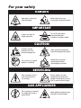
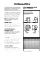
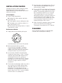
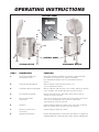
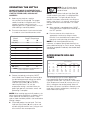
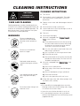
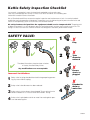
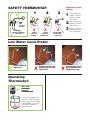
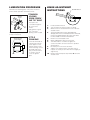
Operators Manual
Installation & Operation
Electric Floor Model Kettles
For units built after August 1999
MODELS:
KEL-25, KEL-30, KEL-40, KEL-40-SH, KEL-60, KEL-80, KEL-100
KEL-25-T, KEL-40-T, KEL-60-T, KEL-80-T, KEL-100-T
KEL-40-SH, KEL-40-TSH, KEL-60-SH, KEL-60-TSH
For a complete Service Manual
refer to www.clevelandrange.com
™
Cleveland
Enodis
1333 East 179th St., Cleveland, Ohio, U.S.A. 44110
Phone: (216) 481-4900 Fax: (216) 481-3782
Visit our web site at www.clevelandrange.com
SE95036 Rev. 6
For your safety
DANGER
Keep clear of pressure
relief discharge.
Keep hands away from
moving parts and pinch points.
IMPORTANT
Do not fill kettle above
recommended level
marked on outside of kettle.
Inspect unit daily for
proper operation.
CAUTION
Surfaces may be
extremely hot! Use
protective equipment.
Wear protective equipment
when discharging hot product.
Do not lean on or place
objects on kettle lip.
Stand clear of product
discharge path when
discharging hot product.
SERVICING
Shut off power at main
fuse disconnect prior
to servicing.
0
Ensure kettle is at room
temperature and pressure
gauge is showing zero or less
prior to removing any fittings.
GAS APPLIANCES
Do not attempt to operate
this appliance during a
power failure.
Keep appliance and area free
and clear of combustibles.
INSTALLATION
GENERAL
Installation of the kettle must be accomplished by
qualified electrical installation personnel working
to all applicable local and national codes.
Improper installation of product could cause injury
or damage.
This equipment is built to comply with applicable
standards for manufacturers. Included among
those approval agencies are: UL, NSF, ASME/Ntl.
Bd., CSA, CGA, ETL, and others. Many local
codes exist, and it is the responsibility of the
owner/installer to comply with these codes.
Note: Maximum voltage for LVD (low volt
directive for Europe) to be 440 volts for CE
marked appliances.
CLEARANCE REQUIREMENTS
& RECOMMENDED FLOOR
DRAIN LOCATIONS
Clearance Requirements
Back
Left Side
Right Side *
0
0
12'
* Minimum recommended
clearance for service
2" Tangent
Draw-Off
Valve
2" Tangent
Draw-Off
Valve
INSPECTION
RECOMMENDED
FLOOR DRAIN
RECOMMENDED
FLOOR DRAIN
Before unpacking visually inspect the unit for
evidence of damage during shipping.
If damage is noticed, do not unpack the unit, follow
Shipping Damage Instructions shown below.
A
A
B
B
SHIPPING DAMAGE
INSTRUCTIONS
RECOMMENDED
FLOOR DRAIN
RECOMMENDED
FLOOR DRAIN
12" x 12"
C
If shipping damage to the unit is discovered or
suspected, observe the following guidelines in
preparing a shipping damage claim.
1. Write down a description of the damage or the
reason for suspecting damage as soon as it is
discovered. This will help in filling out the claim
forms later.
C
D
D
Tilting
Models
Stationary
Models
Recommended Floor Drain Locations **
Model #
A
B
C
D
2. As soon as damage is discovered or suspected,
notify the carrier that delivered the shipment.
KEL-25
22 3/8”
34”
5 1/4”
11 1/4”
KEL-30
25 3/8”
37”
6 3/4”
12 3/4”
3. Arrange for the carrier's representative to
examine the damage.
KEL-40
28 5/8”
40”
7 3/4”
13 3/4”
KEL-40-SH
32 1/2”
44”
9 1/2”
15 1/2”
4. Fill out all carrier claims forms and have the
examining carrier sign and date each form.
KEL-60
32 1/2”
44”
9 1/2”
15 1/2”
KEL-80
35 7/8”
47”
11 1/4”
17 1/4”
KEL-100
38 3/8”
50”
12 1/2”
18 1/2”
KEL-25-T
22 1/4”
51 3/4”
4
24”
INSTALLATION
The first installation step is to refer to the
Specification Sheets or Specification Drawings for
detailed clearance and drain requirements in
order to determine the location of the kettle. Next,
carefully cut open the shipping carton for easy
removal of the kettle.
KEL-40-T
26
56
5 1/2”
28 1/2”
KEL-60-T
29 3/4”
62 1/2”
5 1/2”
31”
KEL-80-T
30 1/2”
65 3/8”
5 1/2”
35 1/2”
KEL-100-T
34 1/8”
69 1/4”
4”
40 1/2”
**
Above dimensions apply to standard 2" Tangent Draw-Off Valve
only. For other valves consult factory.
RED
YELLOW
BLACK
4" MINIMUM,
6" RECOMMENDED
RED
BLACK
SINGLE
PHASE
BLUE
RED
THREE
PHASE
BLACK
RECOMMENDED
FLOOR
FLOOR SLOPE
DRAIN
1" IN 4'
Note: Maximum voltage for LVD (low voltage
directive for Europe) to be 440 volts for CE
marked appliances.
BLUE
RECOMMENDED FLOOR
DRAIN DETAIL
RED
YELLOW
BLACK
PIPE DRAIN
RECOMMENDED
MINIMUM VALVE
SIZE PLUS 1"
L1 L2 L3
L1
L2
The kettle is wired for 3-phase operation at the
factory. For single phase operation, rewire the
terminal block to that shown in the above diagram.
ASSEMBLY
Note: Ensure main power is turned off before
connecting wires.
FLANGED
FOOT (5" DIA)
3 1/8"
(3) 7/16" DIA.
HOLES
Flanged Foot Detail
Position the kettle in it's permanent location, and
level the kettle by turning the adjustable flanged
feet. Once positioned and leveled, permanently
secure the kettle's flanged feet to the floor using
5/16" lag bolts and floor anchors (supplied by the
installer). There are three bolts required to secure
each of the flanged feet.
WIRE CONNECTION
Install in accordance with local codes and/or the
National Electric Code ANSI/NFPA No. 70-1990
(USA) or the Canadian Electric Code CSA
Standard C22.1 (Canada). A separate fused
disconnect switch must be supplied and installed.
The kettle must be electrically grounded by the
installer.
The electrical supply must match the power
requirements specified on the kettle's rating plate.
The copper wiring must be adequate to carry the
required current at the rated voltage.
Stationary Models
Remove the screws securing the dome-shaped
service cover underneath the kettle and remove
the cover. A wiring diagram is affixed to the inside
of cover. Fasten permanent copper wiring to the
three-connection terminal block, Be sure to
connect ground wire to the separate ground
terminal connector (ground lug). Slide the cover's
slot over the wiring and secure the cover to kettle
with the screws.
Tilting Models
First remove the handwheel by loosening the allen
screw. Then remove the two screws at the front
and rear of the console cover and remove the
cover. A wiring diagram is affixed to the underside
of the console cover. Feed permanent copper
wiring through the cut-out in the bottom of the
console, and fasten to the three-connection
terminal block. Be sure to connect the ground
terminal connector (ground lug). Replace the
console cover and handwheel.
WATER
The sealed jacket of the electric kettle is
precharged with the correct amount of a waterbased formula, and therefore, no water connection
is required to the kettle jacket. The kettle can be
equipped with optional hot and cold water taps,
the taps require 1/2" copper tubing as supply
lines.
INSTALLATION CHECKS
Although the kettle has been thoroughly tested
before leaving the factory, the installer is
responsible for ensuring the proper operation of
kettle once installed.
Visual Checks
1. Check Tilting (tilting kettles):
A/ Gearbox tilts kettle smoothly and freely.
2. Insure there are:
5. Raise the kettle to the upright position. The Low
Water Indicator Light (Red) (3) should go out
when the kettle is upright.
6. Turn the ON/OFF Switch/Solid State Temperature
Control (1) to "10" (Max.) and allow the kettle to
preheat. The green light should remain on until
the set temperature (260°F/127°C) is reached.
Then the green light will cycle ON and OFF,
indicating the element is cycling ON and OFF to
maintain temperature. Fill the kettle with cold
water to the steam jacket’s welded seam. Refer
to the Temperature Range Chart for the time
required to bring the water to a boil.
A/ Three lag bolts securely holding each foot
B/ The bottom cover (stationary kettles) is in
place and held with a nut.
7. When all testing is complete, empty the kettle
and turn the ON/OFF Switch/Solid State
Temperature Control (1) to the “OFF” position.
C/ The console cover (tilting kettles) is in place
and held with a screw.
CLEANING
Performance Checks
1. Supply power to the kettle by placing the
150
200
100
30
10
300
40
0
IR
NT A
VE
0
250
20
50
50
60
psi
350
400
kPa
fused disconnect switch to the "ON" position.
2. Before turning the kettle on, read the
Vacuum/Pressure Gauge (4). The gauge's
needle should be in the green zone. If the
needle is in the "VENT AIR" zone, follow Kettle
Venting Procedure in the Service Manual.
3. Turn the kettle's ON/OFF Switch/Solid State
Temperature Control (1) to "1" (Min.). The Heat
Indicator Light (Green) (2) should remain lit,
indicating the element is on, until the set
temperature is reached (130°F/54°C). Then the
green light will cycle on and off, indicating the
element is cycling on and off to maintain
temperature.
4. Tilt the kettle forward (tilting models only). After a
few moments the Low Water Indicator Light
(Red) (3) should be lit when the kettle is in a
tilted position. This light indicates that the
element has automatically been shut off by the
kettle's safety circuit. This is a normal condition
when the kettle is in a tilted position.
After installation the kettle must be thoroughly
cleaned and sanitized prior to cooking.
OPERATING INSTRUCTIONS
CONTROL PANEL
6
5
7
4
8
3
9
3.
2
1
10
OFF
1.
4.
5.
KE95555-2-A
4.
5.
2.
6.
8.
8.
CONTROL PANEL
TILTING KETTLE
STATIONARY KETTLE
General Parts Drawing
ITEM #
DESCRIPTION
FUNCTION
1.
On-Off Switch/Solid State
Temperature Control
Turns kettle ON/OFF and allows the operator to adjust the kettle
temperature in increments from 1 (Min.) to 10 (Max.).
(see Temperature Range Chart in the Operating Instructions
section).
2.
Heat Indicator Light (Green)
When lit, indicates that the kettle element is on.
Cycles ON-OFF with element.
3.
Low Water Indicator Light (Red)
When lit, indicates that the kettle is low on water and will not operate
in this condition. This will also light when the kettle is tilted.
4.
Vacuum/Pressure Gauge
Indicate steam pressure in PSI inside steam jacket as well as
vacuum in inches of mercury.
5.
Pressure Relief Valve
(not shown)
This valve is used to vent the kettle and in the unlikely event there is
an excess steam build-up in the jacket, this valve opens
automatically to relieve this pressure.
6.
Tilt Wheel
Used for tilting the kettle up or down. Some units have an optional
Power Tilt Control Switch located in the same position.
7.
Power Tilt Control Switch
(not shown)
Used for tilting the kettle up or down.
8.
Tangent Draw-Off Valve
Used for draining product or wash water from kettle. It is supplied as
standard equipment on stationary kettles and is optional on tilting kettles.
OPERATING THE KETTLE
DO NOT LEAN ON OR PLACE OBJECTS ON
KETTLE LIP. SERIOUS INJURY COULD RESULT
IF KETTLE TIPPED OVER, SPILLING HOT
CONTENTS.
1. Before turning kettle on, read the
Vacuum/Pressure Gauge (4). The gauges
needle should be in the green zone. Once
heated, the kettle's normal maximum
operating pressure is approximately 10-12 psi,
while cooking a water base product.
2. Ensure that the electrical service to the kettle
is turned on at the fused disconnect switch.
Temperature
Control
Setting
Approximate
Product Temperature
°F
°C
1. (Min.)
130
54
2.
145
63
3.
160
71
4.
170
77
5.
185
85
6.
195
91
7.
210
99
8.
230
110
9.
10. (Max.)
245
260
118
127
NOTE: Certain combinations of ingredients will
result in temperature variations
Temperature Range Chart
3. Preheat the kettle by turning the ON/OFF
Switch/Solid State Temperature Control (1) to
the desired temperature setting (see above
"Temperature Range Chart"). The Heat
Indicator Light (Green) (2) will remain lit,
indicating the burner is lit, until the
temperature setting is reached. When the
green light goes off, the heaters are off, and
preheating is complete.
NOTE: When cooking egg and milk products, the
kettle should not be preheated, as products of this
nature adhere to hot cooking surfaces. These
types of food should be placed in the kettle before
heating is begun.
4. Place food product into the kettle. The Heat
Indicator Light (Green) (2) will cycle on and
off indicating the elements are cycling on and
off to maintain the set temperature.
NOTE: Do not fill kettle above
recommended level marked on
outside of kettle.
NOTE: The Low Water Indicator Light (Red) (3)
should not be lit when kettle is in upright position
during operation. This light indicates that the
elements have been automatically shut off by the
kettle's safety circuit. It is, however, normal for the
red light to come on when the kettle is in a tilted
position.
5. When cooking is completed place ON/OFF
Switch/Solid State Temperature Control (1) to
the "OFF' position.
6. Pour the contents of the kettle into an
appropriate container by tilting the kettle
forward. Care should be taken to pour slowly
enough to avoid splashing off the product.
NOTE: As with cleaning food soil from any
cookware, an important part of kettle cleaning is to
prevent food from drying on. For this reason, cleaning
should be completed immediately after cooked foods
are removed.
APPROXIMATE BOILING
TIMES
Times in Minutes
Gals.
25
40
60
80
100
Ltrs.
95
150
225
300
375
Standard Wattage
High Wattage*
208V
240V
480V
208V
240V
480V
60
60
100
130
160
45
50
75
100
120
60
75
75
100
120
40
40
50
65
80
30
30
40
50
60
30
30
40
50
60
*High Wattage is only available with 3 phase units.
The accompanying chart shows approximate
times required for electric kettles of various
capacities to boil water. The ON/OFF Switch/Solid
State Temperature Control (1) must be set at "10"
(Max.) throughout the heatup period. Water will
boil about 1/3 faster if the kettle is filled only to the
outer steam jacket's welded seam, resulting in a
kettle filled to 2/3 capacity.
CLEANING INSTRUCTIONS
CAUTION
SURFACES MAY
BE EXTREMELY HOT!
CARE AND CLEANING
Cooking equipment must be cleaned regularly to
maintain its fast, efficient cooking performance and
to ensure its continued safe, reliable operation. The
best time to clean is shortly after each use (allow
unit to cool to a safe temperature).
CLEANING INSTRUCTIONS
1. Turn unit off.
2. Remove drain screen (if applicable). Thoroughly
wash and rinse the screen either in a sink or a
dishwasher.
3. Prepare a warm water and mild detergent solution in
the unit.
4. Remove food soil using a nylon brush.
5. Loosen food which is stuck by allowing it to soak at
a low temperature setting.
6. Drain unit.
WARNINGS
➩
7. Rinse interior thoroughly.
Do not use detergents or
cleansers that are chloride
based or contain quaternary
salt.
Chloride Cleaners
➩
Do not use a metal bristle
brush or scraper.
8. If the unit is equipped with a Tangent Draw-Off
Valve, clean as follows:
a) Disassemble the draw-off valve first by turning
the valve knob counter-clockwise, then turning
the large hex nut counter-clockwise until the
valve stem is free of the valve body.
b) In a sink, wash and rinse the inside of the valve
body using a nylon brush.
c) Use a nylon brush to clean tangent draw-off tube.
d) Rinse with fresh water.
e) Reassemble the draw-off valve by reversing the
procedure for disassembly. The valve's hex nut
should be hand tight only.
Wire Brush &
➩
Steel wool should never be
used for cleaning the stainless
steel.
9. If the unit is equipped with a Butterfly Valve, clean
as follows:
a) Place valve in open position.
b) Wash using a warm water and mild detergent
solution.
Steel Pads
c) Remove food deposits using a nylon brush.
➩
Unit should never be cleaned
with a high pressure spray
hose.
d) Rinse with fresh water.
e) Leave valve open when unit is not in use.
10. Using mild soapy water and a damp sponge, wash
the exterior, rinse, and dry.
NOTES
High Pressure
Spray Hose
➩
Do not leave water sitting in unit
when not in use.
➩ For more difficult cleaning applications one of the
following can be used: alcohol, baking soda, vinegar,
or a solution of ammonia in water.
➩ Leave the cover off when the kettle is not in use.
Stagnant
Water
➩ For more detailed instructions refer to the Nafem
Stainless Steel Equipment Care and Cleaning manual
(supplied with unit).
STAINLESS STEEL EQUIPMENT CARE AND CLEANING
(Suppied courtesy of Nafem. For more information visit their web site at www.nafem.org)
Contrary to popular belief, stainless steels ARE susceptible to rusting.
4. Treat your water.
Though this is not always practical, softening hard water can do much
to reduce deposits. There are certain filters that can be installed to
remove distasteful and corrosive elements. To insure proper water
treatment, call a treatment specialist.
Corrosion on metals is everywhere. It is recognized quickly on iron and
steel as unsightly yellow/orange rust. Such metals are called “active”
because they actively corrode in a natural environment when their atoms
combine with oxygen to form rust.
Stainless steels are passive metals because they contain other metals, like
chromium, nickel and manganese that stabilize the atoms. 400 series
stainless steels are called ferritic, contain chromium, and are magnetic;
300 series stainless steels are called austenitic, contain chromium and
nickel; and 200 series stainless, also austenitic, contains manganese,
nitrogen and carbon. Austenitic types of stainless are not magnetic, and
generally provide greater resistance to corrosion than ferritic types.
With 12-30 percent chromium, an invisible passive film covers the steel’s
surface acting as a shield against corrosion. As long as the film is intact
and not broken or contaminated, the metal is passive and stain-less. If the
passive film of stainless steel has been broken, equipment starts to
corrode. At its end, it rusts.
5. Keep your food equipment clean.
Use alkaline, alkaline chlorinated or non-chloride cleaners at
recommended strength. Clean frequently to avoid build-up of hard,
stubborn stains. If you boil water in stainless steel equipment,
remember the single most likely cause of damage is chlorides in the
water. Heating cleaners that contain chlorides have a similar effect.
6. Rinse, rinse, rinse.
If chlorinated cleaners are used, rinse and wipe equipment and
supplies dry immediately. The sooner you wipe off standing water,
especially when it contains cleaning agents, the better. After wiping
equipment down, allow it to air dry; oxygen helps maintain the
stainless steel’s passivity film.
Enemies of Stainless Steel
There are three basic things which can break down stainless steel’s
passivity layer and allow corrosion to occur.
7. Never use hydrochloric acid (muriatic acid) on stainless steel.
8. Regularly restore/passivate stainless steel.
1. Mechanical abrasion
2. Deposits and water
Recommended cleaners for specific situations
3. Chlorides
Job
Cleaning Agent
Comments
Mechanical abrasion means those things that will scratch a steel surface.
Steel pads, wire brushes and scrapers are prime examples.
Routine cleaning
Soap, ammonia,
detergent, Medallion
Apply with cloth or sponge
Fingerprints & smears
Arcal 20, Lac-O-Nu
Ecoshine
Provides barrier film
Stubborn stains &
discoloration
Cameo, Talc, Zud,
First Impression
Rub in direction of polish lines
Grease & fatty acids,
blood, burnt-on-foods
Easy-off, De-Grease
It Oven Aid
Excellent removal on all finishes
Grease & oil
Any good
commercial detergent
Apply with sponge or cloth
Restoration/Passivation
Benefit, Super Sheen
Water comes out of the faucet in varying degrees of hardness. Depending
on what part of the country you live in, you may have hard or soft water.
Hard water may leave spots, and when heated leave deposits behind that
if left to sit, will break down the passive layer and rust stainless steel. Other
deposits from food preparation and service must be properly removed.
Chlorides are found nearly everywhere. They are in water, food and table
salt. One of the worst chloride perpetrators can come from household and
industrial cleaners.
So what does all this mean? Don’t Despair!
Here are a few steps that can help prevent stainless steel rust.
1. Use the proper tools.
When cleaning stainless steel products, use non-abrasive tools. Soft
cloths and plastic scouring pads will not harm steel’s passive layer.
Stainless steel pads also can be used but the scrubbing motion must
be in the direction of the manufacturers’ polishing marks.
2. Clean with the polish lines.
Some stainless steel comes with visible polishing lines or “grain.”
When visible lines are present, always scrub in a motion parallel to the
lines. When the grain cannot be seen, play it safe and use a soft cloth
or plastic scouring pad.
Review
1. Stainless steels rust when passivity (film-shield) breaks down as a
result of scrapes, scratches, deposits and chlorides.
2. Stainless steel rust starts with pits and cracks.
3. Use the proper tools. Do not use steel pads, wire brushes or scrapers
to clean stainless steel.
4. Use non-chlorinated cleaners at recommended concentrations. Use
only chloride- free cleaners.
5. Soften your water. Use filters and softeners whenever possible.
6. Wipe off cleaning agent(s) and standing water as soon as possible.
Prolonged contact causes eventual problems.
3. Use alkaline, alkaline chlorinated or non-chloride containing cleaners.
While many traditional cleaners are loaded with chlorides, the industry
is providing an ever-increasing choice of non-chloride cleaners. If you
are not sure of chloride content in the cleaner used, contact your cleaner
supplier. If your present cleaner contains chlorides, ask your supplier if
they have an alternative. Avoid cleaners containing quaternary salts; it
also can attack stainless steel and cause pitting and rusting.
To learn more about chloride-stress corrosion and how to prevent it,
contact the equipment manufacturer or cleaning materials supplier.
Developed by Packer Engineering, Naperville, Ill., an independent testing
laboratory.
MAINTENANCE
ALL SERVICE MUST BE PERFORMED BY A QUALIFIED SERVICE TECHNICIAN.
IMPORTANT!
ENSURE KETTLE IS AT ROOM TEMPERATURE AND
PRESSURE GAUGE IS SHOWING ZERO OR LESS PRESSURE
PRIOR TO REMOVING ANY FITTINGS.
Cleveland Range equipment requires little preventative maintenance. We do however provide the following
chart as a guideline for inspection and maintenance to keep your unit functioning at 100%.
INSPECTION AND MAINTENANCE CHECK LIST
The following check should be completed every six months or more frequently if unit is in a high volume
facility.
WARNING: It is imperative that damaged seals be repaired immediately to prevent equipment failure
and/or damage.
ITEM
CHECK
BOTTOM COVER GASKETS
Check to see both
gaskets are in place
and are not cracked
or split.
Kettle Bottom
Gaskets
CONSOLE COVER
Insure there are two screws firmly holding down the cover. If not replace
screws.
HAND WHEEL (hand tilt models only)
Check hand wheel for tightness. If loose tighten allen screw.
TILTING
Check that kettle tilts smoothly. Grease as described in LUBRICATION
PROCEDURE.
(tilting models only)
PRESSURE GAUGE
Check that the gauge does not have moisture on its inside face.
Replace if moisture is present.
Check that the gauge shows a vacuum (needle is well into the Green
zone) when cold and shows between 25-40 psi when unit is hot. If not
follow VACUUM LEAK TEST PROCEDURE.
PRESSURE RELIEF VALVE
Check pressure relief valve as described in PRESSURE RELIEF VALVE
TESTING PROCEDURE.
TEMPERATURE CHECK
Following CALIBRATING PROCEDURE check the inner kettle surface
temperature with a digital surface thermometer and adjust if required.
Kettle Safety Inspection Checklist
Just recently a competitor’s steam jacketed kettle exploded causing serious personal injury and damage to a kitchen. In most cases these accidents are caused by poor
maintenance and/or incorrect installation.
We at Cleveland would like to restate that regular inspection and maintenance of units is essential to obtain
trouble free and safe operation of equipment. Inspections must include testing of the pressure relief valve and
checks of the operating system to insure that it has not been altered.
No safety features designed into the equipment should ever be tampered with. Tampering with
or bypassing controls is a very dangerous practice and unfortunately we have seen several cases of this. Following is a short list of the most common and the most dangerous alterations performed on kettles.
SAFETY VALVE:
1
✘
Plug
✔
✔
✔
✔
2
The above illustrations show the three variations
of factory installed Safety Valves.
Any modifications are unacceptable.
Incorrect Installations
1
Safety valve has plug threaded into the discharge opening preventing any steam from escaping.
2
Safety valve’s tube diameter has been reduced.
3
Safety valve is sticking, frozen shut or plugged. To test, refer to Service
Bulletin SE90038 rev. 2, “Pressure Relief Valve Periodic Testing”.
4
Safety valve is plumbed to a drain or water line creating back pressure and reducing flow.
3
✘
Tube
diameter
reduced
✘
Frozen,
stuck, or
plugged
✘
4
Plumbed to
drain or
water line
SE90047
SAFETY THERMOSTAT:
1
✔
Probe
fully
inserted
in tube
Wiring is properly
connected
✘
Probe
removed
partially
Incorrect Installations
2
✘
Probe
removed
completely
3
✘
Thermostat
electrically
bypassed
1
Safety thermostat
probe is not completely inserted
into tubing.
2
Safety thermostat
probe is removed
from tubing.
3
Safety thermostat
electrical connection is bypassed.
Low Water Level Probe:
(A)
(B)
✔
Probe properly
attached
✘
Probe bypassed by
running (A) an additional wire
Operating
Thermostat:
265º
✔
260º - 270º
MAXIMUM
KETTLE
TEMPERATURE
If maximum temperature is
not in this range (on empty
kettle), refer to the “Calibrating Procedure” in the unit’s
Installation, Operation &
Service Manual.
✘
Probe bypassed by
(B) grounding the
connecting wire
LUBRICATION PROCEDURE
Lubricate the following parts every three months to
insure smooth operation and reduce wear.
3/8" Allen wrench
TRUNNION
HOUSING,
WORM SCREW
AND TILT GEAR
Adjusting
Screw
Worm
Screw and
Tilt
Gear
Cross
Bar
These parts are
accessed through the
top cover of the
console.
Apply grease to gear
teeth. Check for
excessive play and adjust with adjusting screw located
on top of cross bar.
Trunnion Housing
Grease Nipple
HINGE ADJUSTMENT
INSTRUCTIONS
KETTLE
TRUNNIONS
On the left hand side of
the kettle there are two
grease nipples on the
top back portion of the
trunnion housing. On the
right hand side of the
kettle you must remove
the console cover to
access the grease
nipple.
1.
2.
3.
4.
5.
6.
7.
8.
9.
10.
Insert 3/8" Allen wrench.
Turn clockwise to relieve tension on spring.
While tension is released remove one of the two
slotted screws.
To prevent Allen wrench from springing back
abruptly while the second slotted screw is removed,
insert a pin (approximately 1/8") in the hole where
the first slotted screw was removed from.
Remove second slotted screw.
While holding Allen wrench remove pin.
Turn Allen wrench clockwise to tighten or
counter-clockwise to loosen tension to produce
desired effect.
Re-insert pin in one of the two holes.
Tighten one slotted screw in the other hole (it
may be necessary to turn Allen wrench slightly to
align holes).
Remove pin and repeat step number 9. for other
slotted screw.