1
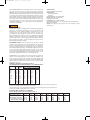
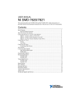
F-P72:TEMPLATE
8/19/10
12:11 PM
Page 1
Bulletin F-P72
Series P72 Industrial Body Flowmeters
Specifications - Installation and Operating Instructions
2-1/2
[63.5]
G
REMOVAL
CLEARANCE
5-23/32
[145.26]
SCALE
A1
A
NPT (AS LISTED)
B
HEX CONNECTION
F
NPT
C
E
P72-A With Optional NPT
D
FEMALE NPT
(OPTIONAL)
2-1/2
[63.5]
5-23/32
[145.26]
SCALE
H
ØL
ØK
OUT
I
IN
A
11-1/32
[280.19]
1-1/2˝ 16-15/16
[430.21]
NPT
3/4˝
B
3-25/64
[86.12]
4-1/4
[107.95]
C
2-53/64
[71.83]
4
[101.6]
J
FLANGE VERSION FOR P72-A/P72-B
(STANDARD)
P72-B With Flange
D
4-43/64
[118.67]
6-29/64
[163.91]
E
3-39/64
[91.68]
5-1/32
[127.79]
F
2-35/64
[64.69]
3-29/64
[87.71]
G
3
[76.2]
5
[127]
DWYER INSTRUMENTS, INC.
P.O. BOX 373 • MICHIGAN CITY, INDIANA 46361, U.S.A.
Flange H
12-1/4
3/4˝
[311.65]
1-1/2˝ 18-5/8
[473.19]
22-35/64
3˝
[572.64]
26-3/8
4˝
[669.86]
I
4-5/8
[117.6]
5-15/16
[151.13]
6-7/64
[155.18]
7-1/2
[190.5]
Phone: 219/879-8000
Fax: 219/872-9057
J
4-1/16
[103.38]
5-11/16
[144.78]
6-7/64
[155.18]
7-1/2
[190.5]
ØK
2-3/4
[69.85]
3-7/8
[98.55]
6
[152.4]
7-1/2
[190.5]
ØL
3-7/8
[98.55]
5
[127]
7-1/2
[190.5]
9
[228.6]
# of
Flange Opening
Bolt Holes Diameter
4
(1-1/8˝)
4
(2˝)
4
(3-1/2˝)
8
(4-1/2˝)
www.dwyer-inst.com
e-mail: [email protected]
F-P72:TEMPLATE
8/19/10
12:11 PM
Page 2
The Series P72 Flowmeters are heavy bodied meters for corrosives, gases, and
high purity fluids. These meters are designed specifically for demanding
applications. They are economically priced meters ideal for caustic solutions as well
as liquid chlorine, sodium hypochlorite and chlorine gas. The Series P72 Flowmeters
are suited for water treatment facilities that deal with these aggressive types of
gases and fluids. The P72-A is comprised of P72 and polysulfone, while the P72-B
has all P72 wetted components for maximum corrosion resistance. Units have a fullscale accuracy of ±2% and can be disassembled quickly without the meter being
removed from the pipeline for easy cleaning. The Series P72 Flowmeters are
available with standard 3/4˝, 1-1/2˝, 3˝, and 4˝ flange connections. Optional NPT
connections are also available.
WARNING
SPECIFICATIONS
Service: Compatible gases or liquids.
Wetted Materials:
P72-A: P72, polysulfone;
P72-B: P72.
Temperature Limits: See operating limits.
Pressure Limits: See operating limits.
Accuracy: ±2% of full scale.
Repeatability: ±1/2% of indicated flow rate.
Process Connections: 3/4˝, 1-1/2˝, 3˝ and 4˝ flange connection with optional
NPT connection available.
Weight: 3 lb (1.4 kg) for 3/4˝, 9 lb (4.1 kg) for 1-1/2˝, 14 lb (6.4 kg) for 3˝, and 18
lb (8.2 kg) for 4˝.
SAFETY PRECAUTIONS
Personnel safety should be considered before pressurizing and operating the
system. There are numerous possibilities for error in system operation and
maintenance as well as component installation. Because human eyes must
necessarily come into close proximity with the flowmeter to read it, it is
recommended that safety shielding be used with the meter along with safety
glasses. Another protective measure is to use a sheet of transparent, high-impact
material in a broad area in front of the meter. If hazardous, toxic, or flammable
fluids are being metered, recommended safeguards should include methods to
protect personnel from splash or rebound. A method of quick, safe removal of
dangerous fluids should also be included.
RECOMMENDED PIPING: Series P72 Flowmeters generally have no special
straight run or other piping requirements. Inlet piping should be the same size as
the meter connection. Some effect on meter accuracy may occur at high flow
velocities if inlet piping guidelines are violated. Please refer to the table below.
When installing on different size pipe, use standard pipe adapters and come into
the meter inlet with a nipple 8 diameters long of the same size for greatest
accuracy. Control valves should be mounted on the outlet side of the meter. The
use of a three valve manifold around the meter is suggested (per Figures 1 & 2) as
it allows uninterrupted process flow while the meter is being cleaned.
INSTALLATION
PREPARATION: Series P72 Flowmeters are ready to install as-is, although the
sight tube may need repositioning so the scale is visible after installation. First,
remove the protective caps from the connection ports. ALSO, REMOVE THE
PLASTIC SHIPPING TUBING ABOVE THE INLET CAP IN THE METER CORE
TUBE! Check that the float moves freely within the core tube, and that no packing
materials are in the meter.
MAXIMUM FLOWS (WITHOUT EFFECTING ACCURACY)
FOR UNDERSIZED PIPES CONNECTED DIRECTLY TO FLOWMETER INLETS
MAX. SCFM AIR @ †
PIPE NPS DATA MAX. *
(ID)2
GPM LIQ. ATMOS 50 PSIG 100 PSIG 200 PSIG
12.6
6.74
0.864
0.132 1.72
3.80
1/4
23.2
12.4
1.59
0.243 2.98
7.00
3/8
37.2
19.8
2.53
0.387 4.74
11.1
1/2
64.9
34.7
4.44
0.679 8.31
19.5
3/4
105
56.1
7.20
1.100 13.47
31.7
1
182
97.2
12.5
1.904 23.32
58.8
1-1/4
248
132
17.0
2.592 31.74
74.6
1-1/2
408
218
28.0
4.272 52.29
123
2
582
311
39.9
6.096 74.56
176
2-1/2
804
480
61.6
9.413 115.2
271
3
1549
827
106
16.209 198.4
467
4
3514
1878
241
36.784 450.0
1059
6
* Data per Cameron Hydraulic Data. Based on 5 FPS max. liquid velocity having no effect on Series P72 flowmeters
accuracy if the inlet pipe is smaller than the meter connections.
† SCFM = 0.445 x (psig + 14.7) x (ID)2. Based on 20 FPS max. air velocity having no effect on Series P72 flowmeters
accuracy if the inlet pipe is smaller than the meter connections.
OPERATING LIMITS FOR SERIES P72 FLOWMETERS
Maximum Non-Shock Working Pressure, PSIG @ °F (bar @ °C)
Body Size and Description
3/4˝ P72-NPT connection
1-1/2˝ P72-NPT connection
3/4˝ P72-Flange connection
1-1/2˝ P72-Flange connection
3˝ and 4˝ P72-Flange connection
70°F (21°C)
270 (19)
180 (12)
150 (10)
150 (10)
150 (10)
80°F (26°C)
270 (19)
180 (12)
150 (10)
150 (10)
150 (10)
100°F (37°C)
250 (17)
170 (11)
150 (10)
150 (10)
150 (10)
120°F (48°C)
200 (10)
145 (10)
135 (9)
135 (9)
135 (9)
140°F (60°C)
150 (10)
115 (8)
110 (8)
110 (8)
110 (8)
160°F (71°C)
130 (9)
75 (5)
90 (6)
90 (6)
90 (6)
180°F (82°C) 210°F (98°C)
80 (6)
50 (3)
50 (3)
30 (2)
70 (5)
40 (2)
70 (5)
40 (2)
70 (5)
40 (2)
F-P72:TEMPLATE
8/19/10
12:11 PM
Page 3
FLOWMETER
MAIN
PROCESS
LINE
SHUT-OFF
VALVES (2)
BY-PASS
VALVE
FLOW
FIGURE 1: TYPICAL INSTALLATIONVERTICAL LINE FOR LIQUID, GAS, OR VAPOR
Figure 1
Apply wrenches only on the flats or outer rims of the connection ports. Avoid overtightening, and do not use wrenches on other portions of the body or sight tube.
When solvent cementing in the vicinity of a meter with a polysulfone sight
tube, the tube should be removed until the cement dries and fumes clear.
SURGE CHAMBERS & ACCUMULATORS: Flowmeters are more accurate and
less likely to be damaged when the fluid flow is smooth. If the meter must be
installed on a line where reciprocating pumps or compressors causing pulsation
are used, surge chambers or accumulators are strongly suggested to damp the
shock wave.
STARTUP
System flow should be started with the by-pass valve open and meter inlet and
outlet valves closed. After the system is operating, open the meter inlet valve
gradually to equalize internal pressure. Then slowly crack meter outlet valve and
wait for float to stabilize. Finally, slowly open the meter outlet and/or flow regulating
valve all the way and close the system by-pass valve. AVOID SUDDEN SURGES
THAT CAUSE THE METER FLOAT TO SLAM INTO THE TOP OF THE SIGHT
TUBE! Although not essential, the meter sight tube should be filled to a level above
the float on liquid systems. The snorkel tube (present in most standard models)
allows escape of entrapped gases except for a small pocket in the upper end which
helps cushion hydraulic shock. To assure proper filling and to flush any foreign
particles from the meter, operate the system at full flow briefly at startup.
READING FLOW
On transparent sight tube models, read flow directly from the scale as the number
nearest the top edge of the float indicator disk. For magnetically-linked models,
flow is read at the center of the ball indicator.
COMPENSATING FOR SYSTEM CHANGES
To find the correct flow reading for a system whose fluid conditions vary from those
for which the meter is scaled, use the conversion data below. The most practical
method of applying the formulae is to calculate a conversion factor for the new
system conditions, multiplying the scale reading by that factor. In the problems
below, ˝Qs˝ has been assigned a value of ˝1˝ to determine the conversion factor.
(The factory can provide special scales at additional cost for other fluids and/or
units.)
WARNING
DO NOT OPERATE THE FLOWMETER ON A SYSTEM
EXCEEDING THE OPERATING LIMITS OF THE UNIT. WHEN CHANGING
OPERATING CONDITIONS, MAKE SURE THAT THE NEW SYSTEM
CONDITIONS ARE WITHIN THE FLOWMETER OPERATING LIMITS, AND ALL
WETTED MATERIALS ARE COMPATIBLE WITH THE FLUID.
CORRECTING READINGS FOR NEW LIQUID CONDITIONS
Qa = Qs
FLOWMETER
SHUT-OFF
VALVES (2)
MAIN PROCESS LINE
BY-PASS VALVE
FIGURE 2: TYPICAL INSTALLATIONHORIZONTAL LINE FOR LIQUID, GAS, OR VAPOR
SIGHT TUBE ROTATION: On P72-A indication models with polysulfone sight
tubes, grasp the tube firmly BY HAND near the body and twist until the scale faces
the desired direction. USE NO TOOLS!
On P72-B flowmeters, the magnet is encapsulated in the top of the float assembly
to seal it from the wetted system.
ds (df - da)
da (df - ds)
pf
VARIES*
df
VARIES*
*Average for these floats is f = 3.50, df = 217.8.
EXAMPLE: Using a standard brass meter scaled for water (s = 1.00), what is the
conversation factor for an oil with a specific gravity of 0.85?
Qa = 1.00 x
Figure 2
or Qa = Qs
Where:
Qa = Actual flow, GPM (or same units as scale).
Qs = Meter reading from scale, (scale units).
ps = Specific gravity of calibration liquid related to water in
std. atmosphere at 70°F. being 1.00.
pa = Specific gravity of metered liquid, same base.
ds = Density of calibration liquid, lbs/ft3.
da = Density of metered liquid, lbs/ft3.
pf =
Specific gravity of meter float.
df =
Density of the meter float per table.
Material
P72-A/P72-B
FLOW
ps (pf - pa)
pa (pf - ps)
1.00 (8.30 - 0.85)
0.85 (8.30 - 1.00)
= 1.096
F-P72:TEMPLATE
8/19/10
12:11 PM
Page 4
CORRECTING READINGS FOR NEW GAS CONDITIONS
Qg = Qs
Pg x Ts x ps)
Ps x Tg x pg)
Where:
Qg = SCFM, corrected to new conditions.
Qs = SCFM read on meter scale.
Pg = Operating pressure, psia (psig + 14.7).
Ps = Pressure stated on scale, psia (psig + 14.7).
Tg = Operating temperature, absolute (°F + 460).
Ts = Temperature stated on scale, absolute (°F + 460).
pg = Specific gravity of metered gas.
ps = Specific gravity stated on scale.
EXAMPLE: If using a standard meter scale for SCFM Dry Air @ 100 psig, 70°F on
argon (SP. GR. = 1.378) at 50 psig, 100°F., what would the conversion factor be?
MAINTENANCE:
Occasional cleaning of the sight tube and internal sensing elements to assure float
visibility and continued accuracy is the only maintenance necessary for Series P72
Flowmeters. Frequency will depend on the application — in most cases, an annual
cleaning is adequate. It is not necessary to remove the Series P72 Flowmeters
from the pipeline for cleaning or replacing parts. The body remains plumbed into
the pipe, allowing easy service and even installation of different sensing elements
to accommodate new flow rates or fluids.
Upon final installation of the Series P72 Flowmeters, no routine maintenance is
required. A periodic check of the system calibration is recommended. Please follow
the instructions in the manual under “Inspection and Cleaning.” The Series P72
Flowmeters are not field serviceable and should be returned if repair is needed
(field repair should not be attempted and may void warranty). Be sure to contact
customer service to receive a return goods authorization number before shipping.
DISASSEMBLY
Qa = 1.00 x
64.7 x 1.00 x 530
114.7 x 1.378 x 560
= 0.522
Thus, actual flow of argon would be observed scale reading times 0.522.
STEAM
Series P72 flowmeters may be used for vapors such as steam. The conversion
factor may be determined with the following formula:
Mfh = Qm
5.879
Sv
Where:
Mfh = Actual flow, lbs/hr.
Qm = Meter scale reading, standard.
(SCFM Dry Air @ 100 psig, 70°F.)
Sv = Specific volume of media (from steam tables).
EXAMPLE: When using a standard Series P72 gas meter scaled for SCFM Dry Air
@ 100 psig, 70°F, what is the conversion factor for lbs/hr. steam at 50 psig, 300°F?
Mfh = 1 x
5.879
6.727
Thus, actual flow of steam in lbs/hr. would be the observed scale reading times
2.267.
VISCOSITY CONSIDERATIONS:
Each Series P72 liquid flowmeter has a so-called “Viscosity Immunity Ceiling”
(V.I.C.). Usually, if the viscosity of the metered liquid is less than the V.I.C. of the
meter, the accuracy will not be influenced by changes in viscosity. When greater
than the V.I.C., the meter will be influenced significantly, and must be calibrated for
that viscosity. Effects of viscosity on a given flowmeter are not always predictable.
Two apparently similar liquids with comparable densities and viscosities may
impact meter calibrations quite differently. The table below provides general
guidelines for the typical maximum viscosity for meter models without affecting
accuracy.
AVERAGE V.I.C., CENTISTROKES, FOR STANDARD
SERIES P72 FLOWMETERS
100% GPM,
SIZE 6
0.54 - 0.80
1.20 - 2.60
3.80 -7.00
10.0 - 23.0
CTS 100% GPM,
1-1/2˝ SIZE
3
11.0 - 15.0
7
21.0 - 35.0
15 50.0
25 70.0 - 120
CTS
50
100
250
500
WARNING
BE SURE PRESSURE IS FULLY VENTED AND FLUIDS COMPLETELY
DRAINED BEFORE DISASSEMBLING THE FLOWMETER. WEAR SAFETY
GLASSES AND PROTECTIVE CLOTHING IF THERE IS ANY CHANCE OF
EXPOSURE TO HAZARDOUS CHEMICALS.
The sight tubes of all standard Series P72 Flowmeters may be removed by,
depending on model type: (a) removing the cotter pins and pulling the lock rings
out horizontally; (b) removing the bolts from the body/sight tube flange; or (c)
removing the internal snap ring with retaining ring pliers. Using hands only, pull the
sight tube straight up out of the body with a slight twisting motion, lifting it clear of
the body and snorkel or guide rod. Remove the float assembly by lifting it up and
away from the snorkel/guide rod. The core tube assembly may then be lifted out —
if stuck, CAREFULLY pry up at the top of the slot with a brass rod, taking care not
to damage the body or core tube.
INSPECTION & CLEANING
Inspect parts for nicks, scratches, chips, wear, and contaminant build-up. The
edges of the core tube slot, ID of the core tube, and OD of the piston (largest
section at the float assembly bottom) are precision machined. Damage to these
areas can destroy the meter's accuracy. Also inspect the O-ring, the bottom section
of the sight tube, and the inside of the upper body section. Damage to these areas
may result in leaking. Clean, rinse, and dry all parts carefully, including the O-ring,
preferably with a mild detergent and water and a soft cloth or soft tube brush. If
solvents are used, make sure they are compatible with all meter parts (plastic sight
tubes may be attacked by chemical vapors or solvents —consult the factory).
NOTICE
DO NOT SCRAPE OR USE ABRASIVE MATERIALS FOR CLEANING.
F-P72:TEMPLATE
8/19/10
12:11 PM
Page 5
ASSEMBLY
Replace all parts in reverse order of disassembly. Note the small key on the core
tube that must be aligned with a corresponding keyway in the meter body. Seat the
O-ring on the sight tube before assembly (put the metal back-up ring on first for
glass sight tube models). Lubricate the O-ring with a small amount of service
compatible silicone grease or petroleum jelly to facilitate replacement.
After replacing the internals, using hands only, press the sight tube firmly down into
the meter body with a twisting motion. Be careful not to rock the sight tube side to
side and bend the snorkel tube/guide inward where it might interfere with float
movement. Rotate sight tube as necessary for scale visibility and/or alignment of
slots for lock ring tabs. Reinsert lock rings and cotter pins, lower flange and snap
ring (be sure snap ring engages groove in body), or flange bolts (do not over
tighten).
REPLACEMENT PARTS
Under proper care, there should be no need to stock replacement parts. Otherwise,
parts only need to be replaced if damaged. Any visible damage to the entire
surface of the O-ring or sight tube (particularly from the bottom edge) indicates
need for replacement. To insure accuracy, the inside surface of the meter core
tube, slot edges, and OD of the float piston should be free of nicks, chips, with no
visible erosion of any surfaces.
STORAGE REQUIREMENTS
There are no special requirements for Series P72 Flowmeters and parts. They
should be kept in a reasonably clean location away from excessive heat (over
120°F, 48ºC) or chemical or solvent fumes and vapors.
If reassembled correctly, the top edge of the indicator disk or center of the ball
should line up with the scale “zero” (either dotted black or scribed line). If it does
not, disassemble the meter completely and carefully reassemble it, making sure
core tube is completely seated in the body.
If new flow internals are used, the scale may have to be remounted on the sight
tube. Depending on the model type, this can be done either by loosening the
mounting screw, or reattaching the scale with double sided adhesive (new flow
internals are shipped with a new scale).
TROUBLESHOOTING
SYMPTOM
FLOAT HANG-UP
USUAL CAUSE
Caused by particles, sludge, etc. (including failure to remove the
plastic tubing used to block meter float during shipment) inside the
core tube and/or sight tube holding float. A bent snorkel tube/guide
rod (usually caused by careless disassembly or violent surges) may
also be causing float to stick. Violent surges may also unseat the
internals in extreme cases.
FLOAT BOUNCE
Caused by pumping/compressor surges or other pulsation sources,
loose valve disks or similar mechanical components, extreme
violation of inlet piping recommendations, or for gas applications,
harmonics commonly found in systems with low pressure, low
density gas.
APPARENT FALSE
Gas density not according to calibration data (different pressure,
READINGS, GAS METERS temperature, gas, etc.), high water vapor content, saturated gas
going into vapor or condensation phases, partially clogged core tube
slot or foreign matter interfering with float movement, and/or violation
of piping recommendations at high flow velocities.
APPARENT FALSE
READINGS, LIQUID
METERS
Liquid density not according to calibration data (different temperature
or new liquid or liquid mixture), excessive dissolved or suspended
solids or gases, partial clogging of core tube slot or foreign matter
interfering with float movement, or viscosity levels above the meter's
immunity index (V.I.C.). Note: If the meter is suspected of giving false
readings, and none of the causes mentioned is found, please advise
as to the method used in determining the suspected flow “error.”
Each flowmeter is individually calibrated by traceable methods, and
carefully inspected. There may be some error in checking the meter
against another standard.
APPARENT METER
READING MIGRATION
(reading changes but flow
appears constant)
Frequently caused by use of soft disc type valves, which may need
to be replaced with a valve more suited to flow control. Can also be
indicative of changing fluid conditions (density, viscosity, etc.).
Problems with other elements of the flow system, including leaks,
clogged filters, pump/compressor wear, etc. may first appear as a
change in meter reading — one of the functions of a flowmeter.
If at the junction of the body and sight tube, it is indicative of either
(a) damaged O-ring (most common); (b) damaged sight tube; or (c)
damage to the gland section of the body. It may also be caused by
improper reassembly of the flowmeter in the field. If there is leakage
at the pipe connections to the meter, it is probably caused from overtightening pipes on a prior installation.
LEAKAGE
SUGGESTED REMEDY
Remedies include tapping the meter gently to temporarily dislodge the
float, but if problem reoccurs, meter should be disassembled & cleaned,
and/or snorkel/guide rod straightened. If hang-up caused by sludge or
pipe scale, clean lines and install a filter or other form of cleaner in supply
line. If surges have caused the internals to unseat, install a de-surger,
accumulator, etc. You may also wish to order a buffer kit — the buffer
serves as a resilient cushion for the float, and prevents unseating.
Modification of piping, such as addition of a de-surger, receiver,
accumulator, vibration eliminators, loops, hoses, etc. between the source
and meter should remedy the problem. Severe vibration may ultimately
damage the meter, and should be avoided. If "bounce" seems to be from
some other source, or shocks such as "water hammer" (a potentially
dangerous condition), discontinue using the meter and contact factory.
Remedies include checking meter pressure & temperature, determining
actual gas mixture density and correcting with appropriate formulae in
this bulletin. Modifying inlet piping, relocating meter to point of higher
temperature and/or lower pressure to eliminate vapor or condensation
phase effects, and/or cleaning the meter (install filter or other form of
cleaner if dirt repetitive problem) may also be required. If accuracy still
questioned, return core tube/float assembly for calibration check.
By determining the actual density (due to changes in mixture,
temperature, etc.), the correction formula may be applied. If dissolved
gases are in the liquid, some elimination means should be provided on
the supply side (also recheck all piping, as improper seals at connection
points are common sources of air in the liquid). If the metered liquid is
near the boiling point producing partial "flash gas" at the meter, relocate
the meter to point of lower temperature and/or higher pressure, or cool
lines and/or increase system pressure. Note: It is potentially dangerous
to meter near the "flash point" of any fluid, and this practice should be
avoided. Consult the factory for recommendations. The previous
recommendations regarding cleaning the meter and/or filtration will also
solve problems due to dirt. If metering liquids with high viscosities,
consult the factory (may require special calibration). If none of these
causes seem to be present, return meter core tube/float assembly along
with application data.
Verifying the proper fluid conditions are known and applying correction
formulae as needed will remedy problems associated with changing
fluids. Cleaning, servicing, and replacement and/or repair of other system
components may be required.
Replace any damaged parts immediately; using the proper assembly
procedures indicated in this instruction and the assembly detail drawings.
Remove the body and inspect for damage — if none is visible, check pipe
threads, reapply proper thread lubricant/sealant, and reinstall. If leak
persists, replace meter body.
Note: All Series P72 Flowmeters are hydrostatically pressure tested before they are shipped. Dwyer Instruments, Inc. encourages you to contact the
factory with any questions regarding proper installation and operation of Series P72 Flowmeters.
F-P72:TEMPLATE
8/19/10
12:11 PM
©Copyright 2010 Dwyer Instruments, Inc.
Page 6
Printed in U.S.A. 08/10
DWYER INSTRUMENTS, INC.
P.O. BOX 373 • MICHIGAN CITY, INDIANA 46361, U.S.A.
Phone: 219/879-8000
Fax: 219/872-9057
FR# R1-443839-00
www.dwyer-inst.com
e-mail: [email protected]