1
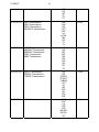
NUMBER:
GROUP:
DATE:
21-003-07
Transmission
February 9, 2007
This bulletin is supplied as technical information only and is not an authorization for repair. No part of this publication may be reproduced, stored in a retrieval system,
or transmitted, in any form or by any means, electronic, mechanical, photocopying, or otherwise, without written permission of DaimlerChrysler Corporation.
THIS BULLETIN SUPERSEDES TECHNICAL SERVICE BULLETIN 21-008-06, DATED
April 8, 2006, WHICH SHOULD BE REMOVED FROM YOUR FILES. ALL REVISIONS
ARE HIGHLIGHTED WITH **ASTERISKS** AND INCLUDE AN ADDITIONAL
VEHICLES, TRANSMISSIONS AND CAUTION STATEMENT.
SUBJECT:
Automatic Transmission Diagnostic Tear Down Procedure
OVERVIEW:
This bulletin provides a procedure to determine repair versus replacement of an automatic
transmission assembly. Follow the proper repair procedure based on the transmission
type. This procedure is to be used after the transmission has been removed from the
vehicle.
Every replaced transmission assembly returned to DaimlerChrysler must include a
properly completed Diagnostic Checksheet. This sheet must be attached to the
transmission bellhousing. Refer to Warranty Bulletin D-06-08 for additional information.
MODELS:
1995
(AA)
Spirit/Acclaim/LeBaron Sedan
1995 - 2003
(AB)
Ram Van/Wagon
1995
(AJ)
LeBaron Coupe/LeBaron Convertible
1997 - 2004
(AN)
Dakota
1995 - 2002
(BR/BE)
Ram Truck
2004 -**2007**
(CS)
Pacifica
1998 - 2003
(DN)
Durango
**2007
(D1/DC)
Ram Truck**
2002 -**2007**
(DR/DH)
Ram Truck
1995 - 2000
(FJ)
Sebring/Avenger/Talon
1996 - 2000
(GS)
Chrysler Voyager (International Markets)
2004 - **2007**
(HB)
Durango
**2007
(HG)
Aspen**
1995 - 2000
(JA)
Cirrus/Stratus/Breeze
**2007
(JK)
Wrangler**
21-003-07
-2-
2001- 2006
(JR)
Sebring Sedan & Convertible/Stratus Sedan
**2007
(JS)
Sebring**
1996 - 2000
(JX)
Sebring Convertible
**2007
(KA)
Nitro**
2002 - **2007**
(KJ)
Liberty
2002 - 2005
(KJ)
Cherokee (International Markets)
1995 - 2004
(LH)
Concorde/Intrepid/Vision/LHS/New Yorker
/300M
2005 - **2007**
(LX)
300/Magnum/Charger
2005 - **2007**
(LE)
300C/300C (International Markets)
2005 - **2007**
(ND)
Dakota
1996 - 2000
(NS)
Town & Country/Caravan/Voyager
2002
(PG)
Chrysler PT Cruiser (International Markets)
1995 - 2005
(PL)
Neon
2001 - **2007**
(PT)
Chrysler PT Cruiser
1997 - 2002
(PR)
Prowler
2001 - **2007**
(RS)
Town & Country/Caravan/Voyager
2001 - **2007**
(RG)
Chrysler Voyager (International Markets)
1997 - 2006
(TJ)
Wrangler
2002 - 2006
(VA)
Sprinter
**2007
(VB)
Sprinter**
1999 - 2004
(WG)
Grand Cherokee (International Markets)
2005 - **2007**
(WH)
Grand Cherokee (International Markets)
1999 - 2004
(WJ)
Grand Cherokee
2005 - **2007**
(WK)
Grand Cherokee
2006 - **2007**
(XH)
Commander (International Markets)
2006 - **2007**
(XK)
Commander
1995
(YJ)
Wrangler
1996 - 1998
(ZG)
Grand Cherokee (International Markets)
**2004 - 2007
(ZH)
Crossfire**
1996 - 1998
(ZJ)
Grand Cherokee/Grand Wagoneer
SPECIAL TOOLS/EQUIPMENT REQUIRED:
C-3339A
Set, Dial Indicator
C-3752-A
Puller Set
6227
Spring Compressor/Alignment
8257
Support Stand
-38261
Plate, Alignment
8266A
Fixtures, End Play
8266-12
Adapter, Geartrain End Play
9082
Remover, Bearing
21-003-07
REPAIR PROCEDURE:
NOTE: **For detailed information, Refer to TechCONNECT 21 - TRANSMISSION AND
TRANSFER CASE or the appropriate service manual in Section 21 for
specific information regarding disassembly and repair procedures**.
40TE, 41TE/AE, 42LE/RLE and **62TE** Transmissions
1. Remove fluid using approved Team PSE Automatic Transmission Fluid X-changer or
equivalent.
2. Remove torque converter (keep with unit).
3. Measure input shaft end play.
4. Remove input speed sensor.
5. Remove pump assembly.
6. Remove input clutch assembly.
7. Remove front sun gear assembly.
8. Remove front carrier/rear annulus assembly.
9. If transmission is determined to be greater than 70% failed follow steps 10 through 13.
If transmission is determined to be less than 70% failed, refer to the service
information available in TechCONNECT or the appropriate service manual in Section
21 for detailed repair instructions.
10. Drop #2 thrust bearing into transmission pan.
11. Reassemble transmission by reversing steps 4 through 8.
12. Return the old torque converter using the same method used to ship to dealer. If the
service unit was received with the converter in a separate box within the transmission
package, return the failed unit in this manner. Otherwise, place converter into trans
and install shipping strap and bolts.
13. Return any loose items by attaching to bellhousing in plastic bag.
NOTE: All parts must be returned with transmission.
NOTE: **For detailed information, Refer to TechCONNECT 21 - TRANSMISSION AND
TRANSFER CASE or the appropriate service manual in Section 21 for
specific information regarding disassembly and repair procedures**.
30RH, 30TH, 31TH, 32RH, 36RH, 42RE/RH, 44RE/RH, 46RE/RH, 47RE and 48RE
Transmissions
1. Remove fluid using approved Team PSE Automatic Transmission Fluid X-changer or
equivalent.
2. Remove torque converter (keep with unit).
3. Measure input shaft end play.
4. Remove pump assembly.
5. Loosen front band adjustment screw until link can be removed (keep link with unit).
6. Rotate front band and remove (keep with unit).
7. Remove front clutch retainer and rear clutch retainer assembly.
21-003-07
8.
9.
10.
11.
12.
13.
14.
15.
16.
17.
18.
19.
20.
21.
22.
23.
24.
-4-
Remove intermediate shaft snap ring (keep with unit).
Remove front and rear planetary assemblies and drive shell (keep with unit).
Remove low/reverse drum snap rings.
Remove low/reverse drum.
Remove overdrive unit.
Remove overdrive clutch snap ring.
Remove overdrive clutch disc and plates.
Remove overdrive wave spring.
Remove overdrive snap ring.
Remove access cover and gasket.
Expand output shaft bearing snap-ring with expanding type snap ring pliers. Then
push output shaft forward to release shaft bearing from locating ring.
Remove geartrain assembly.
If transmission is determined to be greater than 70% failed follow steps 21 through 24.
If transmission is determined to be less than 70% failed, refer to the service
information available in TechCONNECT or the appropriate service manual in Section
21 for detailed repair instructions.
Drop band adjustment link in pan.
Reassemble transmission by reversing steps 4 through 19.
Return the old torque converter using the same method used to ship to dealer. If the
service unit was received with the converter in a separate box within the transmission
package, return the failed unit in this manner. Otherwise, place converter into trans
and install shipping strap and bolts.
Return any loose items by attaching to bellhousing in plastic bag.
NOTE: All parts must be returned with transmission.
NOTE: **For detailed information, Refer to TechCONNECT 21 - TRANSMISSION AND
TRANSFER CASE or the appropriate service manual in Section 21 for
specific information regarding disassembly and repair procedures**.
45RFE/545RFE and **68RFE** Transmissions
1. Remove fluid using approved Team PSE Automatic Transmission Fluid X-changer or
equivalent.
2. Remove torque converter (keep with unit).
3. Remove the transmission oil pan from the transmission case.
4. Remove the primary oil filter and the oil cooler return filter.
5. Remove the cooler return filter bypass valve.
6. Remove the valve body from the transmission case.
7. Install Support Stand 8257 onto the transmission case.
8. Measure input shaft end play.
9. Remove input speed sensor.
10. Remove extension/adapter housing from the transmission case.
11. Remove front pump cover.
12. Remove front pump assembly. Hold the input shaft during pump removal to prevent
the input clutch thrust bearings from falling out of position.
13. Remove input clutch assembly.
14. Remove the 4C clutch retainer/bulkhead tapered snap-ring from the transmission
case.
15. Remove the 4C clutch retainer/bulkhead from the transmission case.
16. Remove the front 2C clutch pack snap-ring from the transmission case.
17. Remove the 2C clutch pack from the transmission case.
-518.
19.
20.
21.
22.
23.
24.
25.
26.
21-003-07
Remove the reaction annulus from the reaction planetary carrier.
Remove the snap-ring holding the park sprag gear onto the output shaft.
Remove the input/reverse planetary assembly.
Remove the snap-ring holding the low/reverse clutch retainer into the transmission
case.
Remove the low/reverse clutch retainer from the transmission case.
If transmission is determined to be greater than 70% failed follow steps 24 through 26.
If transmission is determined to be less than 70% failed, refer to the service
information available in TechCONNECT or the appropriate service manual in Section
21 for detailed repair instructions. Be sure to check input shaft end play during
reassembly and (if low) disassemble the input clutch assembly to check for thrust
bearings which may have fallen out of position.
Reassemble transmission by reversing steps 3 through 22.
Return the old torque converter using the same method used to ship to dealer. If the
service unit was received with the converter in a separate box within the transmission
package, return the failed unit in this manner. Otherwise, place converter into trans
and install shipping strap and bolts.
Return any loose items by attaching to bellhousing in plastic bag.
NOTE: All parts must be returned with transmission.
NOTE: **For detailed information, Refer to TechCONNECT 21 - TRANSMISSION AND
TRANSFER CASE or the appropriate service manual in Section 21 for
specific information regarding disassembly and repair procedures**.
NAG1 Transmissions
NOTE: Be aware of Sprinter NAG1 characteristics:
•
•
•
•
•
•
•
•
Automatic Transmission Fluid (ATF) requires replacement at every second
maintenance interval 96,000 km (60,000 mi).
Special ATF available from Mopar, p/n 05127382AB.
Drain plugs in the oil pan as well as in the torque converter.
Dipstick, only use special tool 8863B to determine the fluid level.
The bell housing has a special geometry fitting OM612 and OM647 engines.
Several clutch discs are unique for Sprinter.
The Transmission Control Module is fine tuned for the use of the special ATF
based on a commercial vehicle duty cycle.
Identification label on the side of the housing has a different placement and
format.
CAUTION: Using a non-approved ATF may result in shifting concerns and clutch
discs may suffer from premature wear resulting in a non-warrantable
failure of the transmission.
1. Remove fluid using approved Team PSE Automatic Transmission Fluid X-changer or
equivalent.
2. Remove torque converter (keep with unit).
3. Measure input shaft end play.
4. Stand the transmission upright on the converter housing. Be sure to use suitable
spacers between the bench surface and the converter housing since the input shaft
may protrude past the front surface of the housing.
21-003-07
5.
6.
7.
8.
9.
10.
11.
12.
13.
14.
15.
16.
17.
18.
19.
20.
21.
22.
23.
24.
25.
26.
27.
28.
29.
30.
-6-
Loosen electrical connector guide bushing and remove from transmission housing.
Remove transmission oil pan.
Remove oil filter.
Unscrew Torx socket bolts and remove electrohydraulic unit.
Place the transmission in PARK to prepare for the removal of the output shaft nut.
Remove the nut holding the propeller shaft flange to the output shaft and remove the
flange.
Remove the transmission rear oil seal with a suitable slide hammer and screw.
Remove the transmission output shaft washer. Be sure to tag the washer since it is
very similar to the geartrain end-play shim and they must not be interchanged.
Remove the transmission rear output shaft bearing retaining ring.
Position Bearing Remover tool 9082 over the inner race of the output shaft bearing.
Slide the collar on Bearing Remover tool 9082 downward over the fingers of the tool
and remove the output shaft bearing.
Remove the geartrain end-play shim from the output shaft. Be sure to tag the shim
since it is very similar to the output shaft washer and they must not be interchanged.
Remove the bolts holding the transmission housing to the converter housing from
inside the converter housing.
Stand the transmission upright on the converter housing. Be sure to use suitable
spacers between the bench surface and the converter housing since the input shaft
may protrude past the front surface of the housing.
Remove the remaining bolts holding the transmission housing to the converter
housing.
Remove the transmission housing from the converter housing.
Remove output shaft with center and rear gear set and clutch K3.
Remove thrust needle bearing and thrust washer.
Remove input shaft with clutch K2 and front gear set.
Remove clutch K1.
Unscrew Torx socket bolts and remove oil pump. Screw two opposed bolts into the oil
pump housing and press the oil pump out of the converter housing by applying light
blows with a plastic hammer.
If transmission is determined to be greater than 70% failed follow steps 27 through 30.
If transmission is determined to be less than 70% failed, refer to the service
information available in TechCONNECT or the appropriate service manual in Section
21 for detailed repair instructions.
Place rear seal and thrust washer in transmission pan.
Reassemble transmission by reversing steps 3 through 25.
Install torque converter and hold in place with torque converter retaining bracket from
replacement transmission.
Return any loose items by attaching to bellhousing in plastic bag.
NOTE: All parts must be returned with transmission.
POLICY:
Reimbursable within the provisions of the warranty.
NOTE: These labor operation numbers are only to be used when repair exceeds 70%
of the cost of transmission assembly replacement.
-7-
21-003-07
NOTE: Returned transmissions received missing components are subject to
warranty part return chargebacks. See Warranty Administration Manual,
Parts Section, Warranty Parts Return pages P1 through P14 for details.
NOTE: Warranty repairs claiming one of the following Labor Operation Numbers
must include a completed diagnostic sheet. Refer to Warranty Bulletin
D-06-08, available in TechCONNECT under: efiles>Service>Warranty>CDJ
Bulletins, for additional information. If the diagnostic sheet is not returned
with the transmission assembly, the diagnostic tear down time allowance will
be charged back.
NOTE: The use of a Diagnostic time allowance and/or "00" time in place of one of
the below Labor Operation Numbers does not eliminate the requirement to
return a properly completed Diagnostic Sheet. See Warranty Bulletin D-06-08
for additional information.
CAUTION: **The diagnostic sheet is to assist DaimlerChrysler engineering in the
analysis of returned units for root cause and corrective actions. Your
diagnosis and findings are important and can assist in this analysis.
Failure to return a properly completed sheet may result in a chargeback
of $75.00. The chargeback for a transmission replaced that should have
been repaired can result in complete chargeback of all parts markup and
even complete claim chargeback.**
TIME ALLOWANCE:
Labor
Operation
No:
Description
Models
Amount
21-00-21-94
40TE Transaxle
41TE/AE Transaxle
**62TE Transaxle**
AA
AJ
CS
FJ
JA
JX
JR
**JS**
NS
GS
PL
PG
PT
RS
RG
0.8 Hrs.
21-00-21-95
42LE Transmission
LH
0.8 Hrs
21-00-21-96
30TH Transmission
31TH Transmission
AA
AJ
NS
0.8 Hrs
21-003-07
-8GS
RS
RG
PL
PT
21-00-27-91
30RH Transmission
32RH Transmission
36RH Transmission
42LE/RLE Transmission
AB
**AN**
HB
**JK**
**KA**
KJ
LX/LE
ND
PR
TJ
YJ
0.8 Hrs
21-00-27-92
42RE/RH Transmission
44RE/RH Transmission
46RE/RH Transmission
47RE Transmission
48RE Transmission
AB
AN
BE
BR
DN
DR
WG
WJ
ZG
ZJ
1.1 Hrs.
21-00-27-93
45RFE Transmission
545RFE Transmission
**68RFE Transmission**
AN
DN
DR/DH
**D1/DC**
**HB/HG
**JK**
KJ
ND
WG
WJ
WH
WK
1.2 Hrs.
21-00-27-94
NAG 1 Transmission
LX/LE
**KA**
VA
**VB**
WG
WK/WH
XK/XH
ZH
1.2 Hrs.