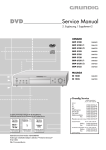
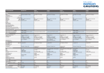
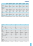
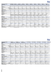
1
Table of Contents
GENERAL
”Service per mouse click “ ((flash-programming,Digi 100 chassis) .................................................................. e_01/01
AUDIO / HiFi
M 100 CD MK II ................................................................................................................................................ e_01/01
CAR AUDIO
Navigation system GPS 3 ................................................................................................................................ e_01/01
DVD
DVD-Player GDV 100D, GDV 100D/002, GDV 110, GDV 200, Xenaro GDP 5100,
GDP 5102, GDP 5120, GDP 6150, Malaga SE 1230 ...................................................................................... e_01/01
SAT
Satellite headend station STC 1880 ................................................................................................................ e_01/01
TV
Colour TV sets wit the chassis Digi Basic 3 - CUC 1832, 1930 and 1931 ....................................................... e_01/01
Flash programming for the new Digi 100 generation ....................................................................................... e_02/01
Special functions (options) for the colour TV sets with the chassis Digi 100 ................................................... e_03/01
Chassis Digi 100 - Flash-Programmer FProg1 ................................................................................................ e_04/01
Chassis CUC 21… - Service Documents ........................................................................................................ e_04/01
Colour TV sets with the chassis CUC 2103 and CUC 2121 ............................................................................ e_05/01
Replacing the memory EEPROMs with the chassis CUC 2103, 2105, 2121, and 2130 ................................. e_07/01
Burned battery socket or battery connecting cable P 37-830/12 and P 37-840/12 SAT, and eqivalent units ... e_08/01
Damage to the bottom corners and edges of the TV sets Lenaro MFW 84 - 6110 and MFW 92 - 6110 ......... e_09/01
TV sets with Digi 100 chassis .......................................................................................................................... o_01/01
TP 750/715 and equivalent units ...................................................................................................................... o_02/01
ST 70-2103 SAT retrofitting not possible .......................................................................................................... o_03/01
Service Information
General
”Service per mouse click “ (flash-programming, Digi 100 chassis)
Dear business partner,
For an optimum stationary and mobile product support of our new CTV
models generation fitted with the DIGI 100 chassis, we are able to offer you
the „Flash-Programmer F-Prog. 1“. This is a service interface enabling the
dialogue between the CTV terminal unit and a desktop or notebook PC.
With the help of a PC and the Flash-Programmer F-Prog. 1, software updating
can be carried out both in the workshop and on-site at the end user.
This kind of updating guarantees an immediate availability of the current
software. With this TV set type, order/delivery delays as well as the repair
through EPROM updating are a thing of the past. We are sure that this way
of software updating will make its entrance also with future products.
The F-Prog. 1 (material number 759880740000) will be offered at a price of
DM 29.90 (EUR 15.29) plus VAT.
Scope of delivery: Flash programmer (RS232 converter)
RS232 cable (25-to-9-pin)
Diskette (PC software and user manual)
We recommend you to make use of the order option via the Internet.
Of course you may still order the F-Prog. 1 also via the Hotline number
++49 911 93394828 or via email: [email protected].
As registered Grundig reseller you are authorized to access the Grundig
spare parts master record. Please let assign you via the below stated address
your individual password after indicating your customer number:
email: [email protected].
MWLE_0201 (8002/8012_o. DK, F, N, S, SF, P / 8003_MT)
Serial No. 01/01
For ordering via the Internet, please follow the instructions below:
- Start the Microsoft Internet Explorer or Netscape Navigator.
- Enter the address: http://www.grundig.com
- Click to Info + Products.
- Position the mouse pointer to Service and click to Reseller Support.
- Click to spare parts: ordering and listings, service documents.
- Login by entering your customer number and password.
- Enter the product number (759880740000) then click to search now.
Note: on this display you will also find the link to downloading the
current device software (spare parts listings and service documents)
- Click to the appearing product number 759880740000.
- Click to put into cart.
- Click to shopping cart in the head bar.
- Click to offer.
- Click to send order.
Central
After-Sales Service
1/2
In cooperation with one of our suppliers we have establisehd for you an offer for a Notebook which,
because of its configuration, is especially appropriate for the on-site updating at the customer.
Manufacturer/ type:
Features:
Fujitsu-Siemens Liteline 325 A
AMD K6-2 500MHz
64 MB RAM
5.0 GB Hard Drive
12.1" HPA Display 1024 x 768
24x CD-ROM
Price:
DM 2,450.00 plus VAT
EUR 1,252.67 plus VAT
NiMH accu
56k modem
MS Windows 98 SE
MS Works Suite 2000
12 months bring-in guarantee
Please place your order directly to :
Grundig AG
Zentralkundendienst
Beuthener Straße 55
D-90471 Nürnberg
Kind regards
Yours
GRUNDIG Central After-Sales Service
Enclosure: Hotline and further contact addresses of the supplier of the PC.
Hotline und weitere Kontaktadressen
Bitte halten Sie vor Ihrem Kontakt mit der PC-Hotline oder mit unseren Servicepartnern immer die Identnr. Ihres Geräts griffbereit (siehe Beispiel Typenschild).
PC-Hotline
Bei Fragen oder Problemen hilft Ihnen gerne die PC-Hotline weiter.
Öffnungszeiten Montag bis Freitag von 9.00 – 18.00 und Samstag von 9.00 – 14.00.
Consumer-PC’s (SCENIC Xpert)
Notebooks
Business-PC’s
Workstations
Fax:
+ 49 (0) 180 / 3 77 70 04 (Tarif DM 0,18/min.)
+ 49 (0) 180 / 3 77 70 01 (Tarif DM 0,18/min.)
+ 49 (0) 180 / 3 77 70 00 (Tarif DM 0,18/min.)
+ 49 (0) 180 / 3 77 70 03 (Tarif DM 0,18/min.)
+ 49 (0) 821 / 8 04 37 50 (Tarif DM 0,18/min.)
Siemens IT Service Call Management Center
Call Center (Störannahme) Öffnungszeiten durchgehend
Fax: + 49 (0) 180 / 5 33 67 79
+ 49 (0) 180 / 5 40 40
weitere Kontaktadressen
Die Adressen der Servicepartner finden Sie in dem zu Ihrem Fujitsu Siemens Produkt mitgelieferten Serviceadressheft oder
im Internet, Webseite http://www.fsc-pc.de/Kontakt.asp
auf dem Abruffax Fax:
in der PC Service Mailbox
+ 49 (0) 821 / 8 04 27 01
+ 49 (0) 821 / 8 04 33 33 (analog)
+ 49 (0) 821 / 81 40 07 (ISDN)
+ 49 (0) 821 / 8 29 71 (ISDN)
Auch Ihr Vertriebspartner, bei dem Sie das Produkt gekauft haben, gibt Ihnen gerne Auskunft. Für weitere Fragen oder Bemerkungen bezüglich unserer Garantie, wenden Sie sich bitte an Ihren Vertriebs- oder Servicepartner oder an:
Fujitsu Siemens Computers GmbH
Service Management
D - 86147 Augsburg
Hotline and further Contact Addresses
Please always keep handy the identification no. of the product concerned (see type plate example) before contacting our PC
Hotline or our service partners.
PC Hotline
In the case of questions or problems our PC Hotline personnel will be glad to assist you. Hours of business on Monday
through Friday from 9 to 18 hours and Saturdays from 9 to 14 hours.
Consumer PCs (SCENIC Xpert)
Notebooks
Business PCs (SCENIC Xpert)
Workstations
Fax:
Notebooks
+49 (0) 180 / 3 77 70 04 (tariff 0.18 DM/min.)
+49 (0) 180 / 3 77 70 01 (tariff 0.18 DM/min.)
+49 (0) 180 / 3 77 70 00 (tariff 0.18 DM/min.)
+49 (0) 180 / 3 77 70 03 (tariff 0.18 DM/min.)
+49 (0) 180 / 3 77 70 04 (tariff 0.18 DM/min.)
+49 (0) 821 / 8 04 37 50 (tariff 0.18 DM/min.)
Siemens IT Service Call Management Center
Call Center (failures reception) Round-the-clock hours of business +49 (0) 180 / 5 40 40
Fax: +49 (0) 180 / 5 33 67 79
Further Contact Addresses
The addresses of our service partners are to be found in the service address booklet supplied with your Fujitsu Siemens
product, or
in the Internet, Web page
http://www.fsc-pc.de/Kontakt.asp
under the polling Fax No.
+49 (0) 821 / 8 04 27 01
in the PC Service Mailbox
+49 (0) 821 / 8 04 33 33 (analog)
+49 (0) 821 / 81 40 07 (ISDN)
+49 (0) 821 / 8 29 71 (ISDN)
Your reseller where you have purchased the product will also be glad to provide you with the necessary information. For
further information on our guarantee please contact your sales or service partner, or:
Fujitsu Siemens Computers GmbH
Service Management
D – 86147 Augsburg
8002/12, 8003/13, 8005/15
Service Information
M 100 CD MK II
AUDIO / HIFI
Unit:
Possible complaint:
CD’s are at times not read, tracks are not found.
Remedy:
Replacement of the microprocessor CIC 1 carrying the designation
D78P048 AGF M 100 CD with a D78P048 AGF CD-05 MK-II.
Workshop:
In the event of a complaint, replace the microprocessor along with new
software.
Serial no. 1/01
Stockkeeping:
CIC 1, D78P048 AGF CD-05 MK-II, part no. 59798 419 0000
46161(8002/8012, 8005/8015)
Returns
analysis
1/1
Service Information
Possible complaint:
The colours of the leads to socket 3 (voltage supply) of the cable tree supplied do
possibly not correspond with the information given in the mounting instructions.
Remedy:
Please consult the excerpt of the updated mounting instructions:
CONNECTIONS TO THE CABLE TREE
1
3
5
7
Socket
1 white
:: to ISO plug of the vehicle (ISO socket)
2 green/yellow
2
4
6
8
________________________________________
SCV
Mute
3 red /white
4 clamp 15/30 ignition (clamp 15) red line
5 blue
Aerial
6 orange
Illumination
7 clamp 15/30 (continuous plus, clamp 30) yellow line
8 brown
Earth
Connections 3 and 5 are transferred directly to plug
11
Plug 1: telephone connection (6-pin) GRUNDIG devices since WKC 5300 RDS
11 pink
Telephone: AF output
12 black
Telephone: earth
When using DAB and a navigation system (to be carried out by a qualified workshop):
Remove plug 1, pins 11 and 12, and insert them into the corresponding plug of the DAB system.
All illustrations show the plug
layout from the rear.
ENGLISH
12
(for the car radio).
CAR AUDIO
Navigation system GPS 3
Serial no.
7
Workshop:
Please observe in the event of a complaint.
Stockkeeping:
none
44241000
(9033)
1/01
Unit:
Returns
analisys
1/1
Service Information
DVD
DVD-Player GDV 100D, GDV 100D/002, GDV 110, GDV 200,
Xenaro GDP 5100, GDP 5102, GDP 5120, GDP 6150, Malaga SE 1230
Controlling the DVD players with the TP 100C, TP 110C and TP 130C TV
remote controls
The basic functions of the above DVD players can be controlled with the TV
remote controls TP 100C, TP 110C and TP 130C.
The DVD players operate with two different remote control codes.
The GDV 100D, GDV 100D/002, GDV 110 and GDV 200 can be controlled
without changing the code.
For controlling the DVD players Xenaro GDP 5100, GDP 5102, GDP 5120,
GDP 6150 and Malaga SE 1230, the remote control code must be changed on
the TV remote controls.
For this, press and hold down the „MODE“ button on the TV remote controls
while pressing the numeric buttons 4, 5 and 6 simultaneously.
To reset the TV remote controls to the factory setting (control of the GDV 100D,
GDV 100D/002, GDV 110 and GDV 200), press and hold down the „MODE“
button on the TV remote controls while pressing the numeric buttons 1, 2 and 3
simultaneously.
When the operating voltage is decreased, the TP 100C, TP 110C and TP 130C
are also restored to the factory setting. For controlling the DVD players Xenaro
GDP 5100, GDP 5102, GDP 5120, GDP 6150 and Malaga SE 1230, the remote
control code must be set again when the battery is replaced.
Stockkeeping:
Telepilot TP 100C (gray)
Telepilot TP 100C (black)
Telepilot TP 110C
Telepilot TP 130C
Part no. 296420614102
Part no. 296420614600
Part no. 296420614202
Part no. 296420614400
43280100 (8002/8012, 8005/8015)
Serial no. 01/01
Unit:
Returns
analysis
1/1
Service Information
SAT
Satellite headend station STC 1880
Possible complaint:
Complete failure of the headend station. The fuse Si 60002 T1 AL, and partly
the fuse Si 60020 T2,5 AL, are broken.
Cause:
Short circuit in the power supply transistor T 60006 (IRF PC 50).
Remedy:
In addition to replacing the power supply transistor, replace the diode D60006
MUR 480 with a wire bridge. This measure reduces the drain voltage and with
that the danger of a damage by overvoltage.
Workshop:
In the event of a failure of the power supply transistor, carry out the change.
In addition, carry out this change as a preventive measure on all STC 1880
which are in the workshop, without regard of the existing failure.
Serial no. 1/01
Stockkeeping:
Transistor IRF PC 50 Part no. 830280505000
Fuse T1 AL
Part no. 831561700400
Fuse T2,5 AL
Part no. 831561700600
4119100000 (8002/8012, 8005/8015)
Returns
analysis
1/1
Service Information
TV
Colour TV sets wit the chassis Digi Basic 3 - CUC 1832, 1930 and 1931
e.g.: Sydney SE 720 Dolby, Xentia M 72-400 Dolby, Denver SE 8250/8 PIP/
Dolby
Possible complaint:
No picture, no sound.
Cause:
Failure of the power supply transistor T 60006 (IRF PC50 or 2SK2699).
Remedy:
In addition to replacing the power supply transistor change the SMD
capacitor CC 60014 from 3.3 nF to 10 nF. This results in a better softstart
function of the power supply.
Workshop:
In the event of a defective power supply transistor replace in addition the
capacitor.
Part no. 867219817300
Part no. 830280505000
Serial no. 1/01
Stockkeeping:
SMD capacitor 10 nF 0805
Transistor IRF PC 50/2SK2699
4116100000 (8002/8012, 8005/8015)
Returns
analysis
1/1
Service Information
TV
Gerät: Colour TV sets Digi 100
Flash programming for the new Digi 100 generation
For the above stated series of sets, no completely programmed EPROM has
been used for the device software. The software is stored in a Flash-Eprom that
can be externally loaded. In this way it is possible to update the software without opening the housing of the TV set.
To do this, the new software is downloaded into the TV set via the serial interface of a PC and the programming socket located at the rear of the TV set using
a download programme and a RS232 converter (Flash-Programmer F-Prog 1).
Required equipment
Flash-Programmer F-Prog 1, part no. 759880740000
Required hardware (minimum)
- PC with processor 486/66 and operating system Windows Version 3.11 or
higher
- 8 MB free main memory
- Free fixed disk capacity of 20 MB
- Internet access or InfoTip-System
Calling up the current device software
The software can be called up from a protected area of the Grundig Internet
Homepage after entering your customer number and a password, or it can be
called up via the InfoTip-System (under „Service Tips“).
Example for calling up the software from the Internet:
420710000 (8002/8012, 8005/8015)
Serial no. 02/01
- Start the Microsoft Internet Explorer or Netscape Navigator.
- Enter http://www.grundig.com and confirm.
- Click to Info + Products on the Grundig Home-Page.
- Position the mouse pointer to Service.
- Click to Reseller Support.
Returns
analysis
1/1
Note: In the retailer support menu, you may applicate for access by entering
your customer number and your address.
- Click to spare parts: ordering and listings, service documents.
- Enter your custumer number and password.
- Click to login.
- Click to spare parts lists and service documents.
2/3
Service Information TV 02/01
- Select the desired software under software download.
- Copy the selected device software into the folder C:\GRUNDIG\Software of
your PC which has been created when installing the F-Prog 1-PC software.
The downloaded packed file (*.zip) then must be unpacked by an appropriate
unpacker for „ZIP“ files (appropriate unpackers can be found, for example,
under www.winzip.com).
ZIP files cannot directly be loaded into the TV set!
Additional hints/particularities for programming with the „F-PROG 1“:
- Before connecting the Flash Programmer, switch the TV set off with its
mains button then connect the programmer when the operating LED
has gone out!
- After starting programming, the operating LED first remains dark then
starts flashing as soon as the Flash memory is deleted.
3/3
Service Information
TV
Setting hints and special functions (options) for the colour TV sets with
the chassis Digi 100 (CUC 1807, 1837, 1838, 1839, 1934, 1935)
e.g.: Elegance 70 M 70-300 Dolby, Elegance 70 MW 70-150/8 Dolby,
Hamburg SE 8240 Dolby, M84-212/8 Dolby, Toronto SE 7216 Dolby
Below you find setting hints and explanations for various functions of the TV
sets with the chassis Digi 100.
1. Power-on behaviour of the set
In the „Special functions“ menu you can select under the „Power on“ menu
item between „automatic“ and „Programme position 1“ .
automatic: the set is switched on with the last power-on mode. For this, the
last recognized programme position and operating mode (standby or
normal operating mode) are stored.
Note: if the set has been switched off with the mains button in standby
mode, it goes again in standby mode after power on and must
definitely be switched on using the remote control.
Programme position 1: the set selects programme position 1 each time it is
switched on.
2. Settings in the „Programme table“ menu
In this menu, further presettings can be programmed in addition to the
channel setting for every programme position.
Note: direct channel entry is only possible in the programme table.
„P+“ reversion point: the reversion point is the limitation of the programme
positions for programme selection using the „P+“ button. This
reversion point is marked with an orange line in the programme table.
To shift the reversion point, it is necessary to shift the programme
position above or below this line according to the direction of shift.
Serial no. 3/01
1-/2-/3- digit programme position selection (3-digit only with a retrofitted
satellite module): for 1-digit programme position selection you must
place the reversion point in the programme table between the
programme positions 1 and 10. For 2-digit programme position
selection place the reversion point between the positions 10 and 100.
Forced settings (forced colour standard, forced mono, fixed assignment of a
multi-channel sound, RF time constant, AFC):
In the „Channel settings“ menu (menu guide: „i“ -> „Programme table“
-> „Edit“ -> „Change channel settings“) you can carry out various
forced settings.
Note: it is also possible to set a forced colour standard for the AV
programme positions in this menu.
4121100000 (8002/8012, 8005/8015)
Returns
analysis
1/2
Service Information TV 03/01
3. Volume adjustment:
You can store a volume setting deviating from the basic volume separately for every
programme position in the „Sound“ menu (blue button) under the menu item „Volume
adjustment“. This adjustment is allowed by the software only if the basic volume is higher than
7 of the 64 steps of the control range.
4. Picture settings (brightness, contrast, colour, etc.):
The desired picture settings are carried out in the „Picture“ menu (red button). Changing the
contrast is only possible with the „manual“ presetting. The presettings „During the day“ and „In
the evening“ are stored with fixed contrast settings. To get a better overview, it is possible to
reduce the large menu scale after selecting the desired menu item by pressing the „OK“
button. In doing so, more menu content is visible and the setting, e.g. colour contrast, is highly
facilitated.
5. Sat radio (only with satellite retrofit kit SER 300A):
Via the menu guide „i“ -> „Infothek“ -> „Sat-Radio“, about 40 pre-stored sat radio stations can
be called up (dark picture screen, only the station name is visible). In this operating mode, the
programme table can be displayed after pressing the „i“ button in order to select/change the
sat radio stations.
6. Time and date:
Each time the set is powered on, the internal software clock is set when receiving a station
broadcasting Teletext.
If only stations without Teletext are received after power on, no clock time can be called up. In
this case, the clock and time can manually be set via „i“ -> „Installation“ -> „Time and date“.
7. AV settings:
The sets with the chassis Digi 100 provide the possibility of individually configuring all
available AV programme positions. The factory settings are:
AV 1 for the connection of a Megalogic video recorder,
AV 2 for the connection of a DVD player (via RGB),
AV 3 (if available) for the connection of a VHS video recorder (a switching voltage is
necessary at the Euro-AV socket Pin 8),
AV 4 for the connection of a VHS camera.
If you wish to change these presettings, you can individually configure all AV connections via
„i“ -> „Installation“ -> „Connections“ . In this menu, various units are preset which can be
activated if they are required. A connection diagram can be displayed by pressing the yellow
button.
In addition own unit profiles can be created via the menu item „Manual AV settings“. These
unit profiles are indicated with „manual“ in the connection diagram. Please note that settings in
the „Manual AV settings“ must correctly be effected in any case, and that preset units at AV 1,
AV 2 etc. are deactivated at the same time (see connection diagram). For example, an
incorrectly set time constant would result in a black/white picture with a VCR signal source.
2/2
Service Information
1.
Chassis Digi 100 - Flash-Programmer FProg1
Additional function through software change (version 1.1)
After replacing the Feature module, the unit-specific settings like colour
registration, noise reduction, picture sharpness, white balance, CRT type, PIP
position, picture geometry, and the customer-specific programme data must be
set up.
The extension of the FProg1 software now makes it possible to read out this data
and to write it into the new module.
This means a considerable decrease of expenditure of work.
TV
1. Chassis Digi 100 - Flash-Programmer FProg1,
2. Chassis CUC 21… - Service Documents
Serial no. 04/01
For reading out and programming the operating software and the unit-specific data
you need the Flashprogrammer FProg1, part no. 759880740000. Please consult for
this also the Service Information ”General, serial no. 01/01“.
The Flash-Programmer comes with the software version 1.0. Please load the current
software, version 1.1, directly from the Internet (see Online Service brochure). This
is to be found under “Reseller Support“, “Software Download“ in the category
”Programming software“, Product group ”DIGI 100”. The updated description of
the FProg1, V1.1 software is to be found under Advice ”Operating instructions FlashProgrammer F-Prog1“.
Stockkeeping: Flash-Programmer FProg1, part no. 759880740000.
E-BS-SA_2801 (8002/8012, 8005/8015) Subject to alteration
Returns
analysis
1/2
2.
Chassis CUC 21… - Service Documents
Service Manual 720100407000
Service Manual, 1st supplement 720100407100
Dear business partner,
despite multiple checks of the printing data we are not immune against
printing errors. For this reason please correct the above documents
according to the following information.
•
Ser vice Manual 720100407000
The following alignment points replace the corresponding alignment
points in the Service Manual, page 2-1.
Alignment
2. Tuner AGC
Preparations
Alignment Process
100MHz oscilloscope: Channel A: Tuner contact 10 or 11.
Ground:
Tuner
Colour video generator: Feed in a colour scale (with switchedoff sound carrier) via the aerial,
≥80dBµV.
Ǻ
8. Screen grid
voltage UG2
Adjust 300mVpp with button
Ǹ or Ƿ.
Call up the dialog line "AGC" via " " (Dialog Center) –>
Service –> "OK" –> Service Code "8500".
Terminate the dialog line "End" "with mem" –> "OK".
Colour video generator:
Use the UG2 control (splitter transformer) to adjust at the
test point having the highest voltage potential a voltage of
112.5V ± 2.5V for 14" picture tubes, and a voltage of 150V
± 2.5V for 15"...21" picture tubes.
Feed in a black test pattern.
Adjust the screen brightness so
that the test pattern just turns dark.
High-resistance voltmeter via 220KΩ:
Test points R, G, B
(picture tube plate).
Determine the test point having the highest voltage.
´E
replaces the oscillogram
The following oscillogram
(CRT plate) of the Service Manual.
78 on page 3-26
´E
•
Service Manual, 1st supplement 720100407100
The following hint replaces the corresponding hint on page 3.
Software version number
Press the "Ǻ" button to call up the "DIALOG CENTER" menu –> OK.
Press "AUX" to display the software version number.
2/2
Service Information
TV
Colour TV sets with the chassis CUC 2103 and CUC 2121
e.g.: P 37-4101 TOP Davio, T 55-4101 TOP Davio, T 55-4104 TOP Lemaxx
Listed below are the unit types on which the option of retrofitting a satellite
retrofit kit SER 2100 has been omitted. In the new GRUNDIG main
catalogue, this is not considered in the technical data. In order to distinguish
the retrofit option, the version marking at the rear panel has been changed
from „VNM“ (retrofitable) into „VNA“ (not retrofitable).
The following unit types are concerned::
CUC 2103
Arcance 37 P 37-2101 MV
Davio 37 P 37-4101 TOP
Davio 37 P 37-4101 TOP/1
Davio 37 P 37-4101 TOP/TR
Davio 37 P 37-4101 GB
P 45-4101 TOP
P 45-4101 MV/TOP
Arcance 51 T 51-2101 MV
Davio 51 T 51-3101 TOP
Davio 51 T 51-3101 TOP/1
Davio 51 T 51-3101 TOP/TR
Davio 51 T 51-3101 MV
Arcance 55 T 55-2101 MV
Davio 55 T 55-4101 GB
Davio 55 T 55-4101 MV
Davio 55 T 55-4101 TOP
Davio 55 T 55-4101 TOP/1
Davio 55 T 55-4101 TOP/TR
Leemaxx 55 T 55-4104 TOP
S 55-806 TOP/TR
CUC 2121
Davio 55 ST 55-854/8 Dolby
Greenville SE 5592 MV/Dolby
Leemaxx 55 ST 55-4105 MV/Dolby
ST 55-839/8 Dolby
ST 55-908/8 Dolby
ST 55-908/8 FR/Dolby
Xentia 55 ST 55-405/8 Dolby
The units
ST 55-734 GB/Dolby and
ST 55-934 GB/Dolby can be
retrofitted with the„VNM“
and „VNA“ marking. With the
„VNX“ marking the retrofit
option is omitted.
Stockkeeping:
IC socket, 56-pin
Serial no. 5/01
Workshop:
On a small number of the Davio 37 P 37-4101 TOP sets with the version
identification „VNM“ (retrofitable), the processor has not been fitted with a
socket but has directly been soldered in. So that the processor board can be
fitted in the event of a SAT retrofitting, you must solder in an IC socket in
place of the soldered-in processor.
Part no. 813090012900
4128100000 (8002/8012, 8005/8015)
Returns
analysis
1/1
Necessary settings after replacing the memory EEPROMs for colour TV
sets with the chassis CUC 2103, 2105, 2121, and 2130
e.g.: P 37-4101 TOP Davio, T 55-4101 TOP Davio, T 55-4104 TOP Leemaxx,
ST 55-854/8 Dolby
Possible complaint:
After replacing the EEPROM CIC82501 (M24C08) the set is not fully operative despite of loading the emergency data set. Especially the teletext function
is restricted.
TV
Service Information
Workshop:
The following settings must be carried out after fitting a new EEPROM
M24C08.
2. Loading the emergency
data set.
Press and hold down the „P-“ button on the
remote control while switching the set on with
the mains switch.
3. Setting the menu colours.
Set the menu item „OEM“ in the Service menu
(access with the code „8500“) to „off“.
4. Geometry, white balance,
AFC, and AGC alignment.
Carry out these settings according to the
Service Manual.
5. Configuration of the
Euro-AV socket „AV 1“
In the „AV 1“ programme position you can
select between „VHS“ and „SVHS“ under the
„Video“ menu item in the „Special Functions“
menu.
Serial no. 7/01
1. Loading the configuration Switch the set on with the mains switch then
data for the teletext decoder. switch it off again when the picture appears on
the screen.
Note: the menu display is shifted to the left!
Note: it is absolutely necessary to keep the order of the first two points to
gurantee the proper functioning of the teletext!
Stockkeeping:
SMD IC M24C08
4130100000 (8002/8012, 8005/8015)
Part no. 830596000800
Returns
analysis
1/1
Service Information
Burned battery socket or battery connecting cable
P 37-830/12 and P 37-840/12 SAT, and eqivalent units
Possible complaint:
Failure of the 12V power supply due to burned battery sockets or battery
connecting cables.
TV
Number: E/08/01; e_tv081e
Cause :
Contact resistance between the battery socket and the plug of the battery
connecting cable.
Remedy:
To ensure the proper fitting accuracy, the battery socket must be replaced along
with the battery connecting cable with the new version.
Stockkeeping:
Battery connection set FFS (battery socket and battery connecting cable).
Part no. 759550410700
TQ42_4101 (Online, 8002, 8012, 8005, 8015)
Alterations reserved.
1
Service Information
Damage to the bottom corners and edges of the TV sets
Lenaro MFW 84 - 6110 and MFW 92 - 6110
Possible complaint:
Damage to the bottom corners and edges on the front side.
TV
Number: E/09/01; e_tv091e
Cause:
Due to the small bottom clearance of the front trim, the corners and edges of the
trim can be damaged when putting down the TV set in an inexpert way.
Remedy:
When transporting the TV set make absolutely sure to put it always down in
horizontal position and not to tilt it to the front to prevent the vulnerable corners
and edges from being dented.
TQ42_4301 (8002, 8012, 8005, 8015)
Subject to alterations.
1
Service Information
TV sets with Digi 100 chassis
Possible complaint:
The TV set switches at times to standby and then after several seconds back to normal
operation.
TV
Number: O/01/01; o_tv011e
Cause:
This failure may be caused by an uncontrolled oscillation of the CVBS input and a faulty
software library of the processor.
Remedy:
To eliminate this failure it is generally necessary to update the unit‘s software. For this
consult the table 1 (software assignment).
- Update the operating software of the TV set. The software required can be downloaded from the Internet.
For this consult also the Service Informationen ”General 01/01“ and ”TV 04/01“
(external).
E-BS-SA_3501 (Online)
Alterations reserved
M
16
14
12
8
10
4
2
6
82
CR80211
P6.1
95
P6.0
1
15
13
11
9
3
TCK
M
TDI
4
7
5
2
TDO
3
1
ST-JTAG
TMS
109
CR80212
n.v.
100n
+H/UP2
33p
CC80211
100
CR80208
10k
CR80206
108
XTAL2
CVBS1B
120
CC80207
n.v.
6MHz
CC80209
121
U RESET
M
Q80205
XTAL1
FBAS
TXT
n.v.
33p
CC80206
CC80210
X
CC80202
0,33u
CVBS2
117
101 P6.6
47p
CVBS1A
n.v.
X
98 P6.3
100 P6.5
CR80203
0
CC80208
n.v.
n.v.
CC80201
CC80205
MA
97 P6.2
99 P6.4
Masse zu Pin 110
V1 MA
MA
MA
VIDEO2
.
SDA2
SCL2
In addition it is necessary to check and change if necessary the circuit of the
Feature module of older TV sets. TV sets and chassis which do not require a change of
the circuit are listed in the tables 2 and 3. The positions of the serial numbers of the TV
sets and chassis are described on page 4.
For the positions of the components concerned on the Feature module please see the
circuit diagram excerpt and the PCB illustrations on page 2.
- Remove the chip capacitor CC80209 (coordinates x71/y78) if provided.
- Connect CIC80000, Pin 117 with ground (e.g. chip capacitor CC80205 (coordinates
x71/y81), replace with a chip jumper, or solder in a wire bridge from Pin 117 to
ground).
CIC80000
0 = TV-on
SDA6000
MQFP128
1
Service Information
CC84078
CR80241
CC84046
1
CIC82001
CC80021
CIC80242
1
CC70455
1
CC80172
CC80171
CR80204
CR70207
CR70224
CR70012
CT70011
CR70013
CT70015
CT80204
CC70010
CR70004
CR70227
CR80192
CR80199
CC80171
1
CNW80191
CC80202
CR82031
CC84078
CR80241
CR80238
CC84046
INC270
CC84044
29306-231.24/4BS(00)
.
CC80249
CC84047
CC82043
1
CC80021
CT80090
CIC82041
CR70098
CC80172
1
CIC70150
CR70159
CR70207
CR70224
CR70161
CC70162
CT70155
1
1
CIC70300
CR70012
CIC70200
CIC70250
CT70015
CR70004
CC70200
CR80199
CC70010
CT80204
80216
CNW80191
CC80205
CC80210
CC80209
CR80203
CT70470
CR70473
CC70306
CC70303
CC70308
CR70319
1
161
CR80114
CR70013
CT70011
CIC70475
1
CR70244
CR70245
CC70154
CR80204
CR80199
1
CC80171
CC80202
CC80208
CR80216
1
CR80203
CC80210
CC80209
CR70345
CR70348
CR70347
CR70346
CR80192
CR80193
CR80007
CR80217
CC80114
CNW80191
CC80205
CR80114
CC70226
CL80109 CC80214
CC80213
CNW80171
CNW80161
CC80204
CNW80181
CNW80144
CR70152
CR80251
CR80252
CR80250
CR80253
CR80254
CC80184
CC80183
CC80182
CC80181
CC80174
CC80173
CC80254
CIC80000
CNW80132
CT80008
CR80006
CL70321 CL70322
CR70344
CC80075
CC80121
CT80108 CC80153 CC80143
CC80163 CR80152 CC80142 CC80131
CC80162 CC80151 CC80133 CC80123
CL80110 CC80161 CC80144 CC80132 CC80122
CR80034
CC80037
CR80036
CR80033
1
CR80032
CR80037
CT80042
CC80031
CT80009
CT80110
CR80089
CC80071
CNW80121
CT80310
CT80308
CT80077
CL80120 CL80119
CIC70180
2
CC80074
CC70309
CC70180
Stockkeeping:
Chip jumper (0 Ω)
Feature module with
updated software
CC84079
CC80073
CR80099
CT80085
1
CC80171
CR70316
CR70410
CR70420
CR70430
CR80071
CR80136
CR80137
CR80127
CR80128
CR80156
CR80157
CR80158
CT80004
CR80004
CR70426
CT70425
CT70422
CR70424
CR70463
CC70460
CR70343
CR70312
CC70313
CR70313
CR70422
CT70306
CR70421
CR70423
CC70316
CR70302
CC70461
CC70476
CR70006
CR70342
CT70305
CT70420
CR70427
CR70464
CC70464
CT70465
CR70461
CC70420
CR70429
CC
70
08
1
CR80009
CT80033
CT80034
CR80082
CC80081
CR80081
CC80233
CR80078
CR80077
CC
70
08
3
CC70004
CL80256
CIC80230
CR80117
CR80118
CR80119
CIC80240
CC
70
08
2
CR80240
1
Version of the PCB with CC80209
CR80265
CR82005
CC82005
CC80072
CR80090
1
CIC82001
CC82021
CT80095
CIC82031
CC82031
CC80076
CT80075
CR80076
CC80205
CC80203
CC70200
CR70473
CNW80171
CT80041
CC70162
1
61
CT80080
CR70244
CR70152
CR70161
CT70155
CIC70180
CC
70
08
4
CR70159
CIC70250
CD70227
CR70303
CC70309
CC70308
CC70306
CC70476
1 CR70245
CIC70150
CR70154
CC80204
CC80254
CR80217
CR80216
1
CIC70300
CR70410
CR70420
CR70430
CT70470
1
CC70303
CIC70475
CR70477
1
CC80202
CR70345
CR70348
CR70347
CR70346
CIC70200
CC70302
CR70302
CR70476
CC70460
CC70180
CR80199
CC80205
CR80114
CC80114
CC80203
CR80192
CR80193
CC80213
CNW80191
CNW80171
CNW80161
CC70316
CR70316
CT70422
CT70425
CR70424
CR70463
1
08
70
CC
CT70420
2
08
70
CR70006
CNW80181
CNW80144
CL70321 CR70455
1
CR80251
CR80252
CR80250
CR80253
CR80254
CC80184
CC80183
CC80182
CC80181
CC80174
CC80173
CNW80132
CT70306
CR70423
CIC80000
CC70226
CC
CC70420
CL70322
CR70344
CR70313
CT80008
CR70343
CR70426
CR70422
CR70421
CR80006
CR70342
CC70313
CR70429
CR70427
CT80108
CR80110
CR80004
CC80075
CNW80121
CR80109
CT80110
CT80077
CT80004
CT80009
CR80034
CT80034
CT80085
CC80074
CR70098
CC80071
CC80131
CC80123
CC80122
CC80121
1
CR80033
CR80032
CR80037
CC80037
CR80036
CR80136
CR80137
CR80127
CR80128
CR80156
CR80157
CR80158
CT80033
CC80031
CC80233
CC80081
CR80081
CR80082
CR80078
CR80077
CR80071
CR80073
CT70305
CC70418
CC70428
3
08
70
CC
CR70418
CR70428
CR80009
4
08
70
CC
CT80080
CR70464
CC70464
CT70465
CR70461
CC70461
CC80073
CC80163 CC80153 CC80143
CC80152 CC80142
CC80151 CC80133
CC80162
CC80144 CC80132
CC80161
CC80214
CR80117
CR80118
CR80119
CR80089
CC80072
CIC80230
CIC80240
CR80099
CR82005
CC82005
CR80256
CR80240
Version of the PCB without CC80209
CT80095
CR80090
CT80090
1
CC82021
TV
CBR80240
CC80249
CC84047
CC84044
CC82043
CR82031
INC270
CC82031
CT80075
CC80076 CR80076
Number: O/01/01; o_tv011e
CC80202
CC80208
Part no.
759880114900
Part no.
295042032100/2200/2300/2400/3100/3200/3300/4100/
4200/4300/4400/4600
Service Information
Table 1: Software assignment
The table below shows the unit-specific assignment of the Feature modules and the part
number of the associated software, the positions marked with xxxx being variable and
indicating the version (e.g. 297981110800).
TV set
ARGANTO 70 MW 70-515 MV/DOLBY
Feature module
Software
295042032200
29798111xxxx
ARGANTO 82 MW 82-515 MV/DOLBY
295042032300
29798113xxxx
ATLANTA FLAT SE 7260 DOLBY
295042034300
29798117xxxx
BOSTON SE 7012 DOLBY
295042034200
29798115xxxx
DAVIO 70 ST 70-292 DOLBY
295042032200
29798111xxxx
DAVIO 70 ST 70-292/8 DOLBY
295042032200
29798111xxxx
DAVIO 70 ST 70-5210 DOLBY
295042032200
29798111xxxx
DAVIO 70 ST 70-5210/8 DOLBY
295042032200
29798111xxxx
ELEGANCE 63 ST 63-300 DOLBY
295042032200
29798111xxxx
ELEGANCE 63 ST 63-300/8 DOLBY
295042032200
29798111xxxx
ELEGANCE 70 M 70-300 DOLBY
295042032200
29798111xxxx
ELEGANCE 70 M 70-3110 DOLBY
295042032200
29798111xxxx
ELEGANCE 70 MW 70-150/8 DOLBY
295042032200
29798111xxxx
ELEGANCE 70 ST 70-300 DOLBY
295042032200
29798111xxxx
ELEGANCE 70 ST 70-300/8 DOLBY
295042032200
29798111xxxx
ELEGANCE 82 MFW 82-3110 MV/DOLBY
295042032100
29798113xxxx
ELEGANCE 82 MW 82-150/8 DOLBY
295042032200
29798111xxxx
HAMBURG SE 8240 DOLBY
295042034200
29798115xxxx
LEEMAXX 72 MF 72-9110/8 DOLBY
295042032100
29798113xxxx
M 70-879/8 DOLBY
295042032100
29798113xxxx
M 72-109 MV/DOLBY
295042032200
29798111xxxx
M 72-798 DOLBY
295042032200
29798111xxxx
M 84-212/8 DOLBY
295042032200
29798111xxxx
MW 82-3112 MV/DOLBY
295042032200
29798111xxxx
SEDANCE 70 M 70-284 DOLBY
295042032200
29798111xxxx
SEDANCE 70 ST 70-284 DOLBY
295042032200
29798111xxxx
SEDANCE 70 ST 70-284/8 DOLBY
295042032200
29798111xxxx
SEDANCE 72 M 72-2110 DOLBY
295042032200
29798111xxxx
SEDANCE 72 M 72-2110 MV/DOLBY
295042032200
29798111xxxx
ST 70-265/8 DOLBY
295042032200
29798111xxxx
ST 70-398 DOLBY
295042032200
29798111xxxx
SYDNEY SE 7240 DOLBY
295042034100
29798117xxxx
TORONTO SE 7216 DOLBY
295042034200
29798115xxxx
TORONTO SE 7216/8 DOLBY
295042034200
29798115xxxx
WIEN SE 6340 DOLBY
295042034200
29798115xxxx
XENTIA 55 M 55-420/8 DOLBY
295042032200
29798111xxxx
XENTIA 63 M 63-420/8 DOLBY
295042032200
29798111xxxx
XENTIA 70 FLAT MFW 70-430/8 DOLBY
295042032100
29798113xxxx
XENTIA 72 FLAT MF 72-430 DOLBY
295042032300
29798113xxxx
XENTIA 72 FLAT MF 72-430/8 DOLBY
295042032300
29798113xxxx
XENTIA 72 M 72-420 DOLBY
295042032200
29798111xxxx
XENTIA 72 M 72-420/8 DOLBY
295042032200
29798111xxxx
XENTIA 82 FLAT MFW 82-430/8 DOLBY
295042032900
29798121xxxx
TV
Number: O/01/01; o_tv011e
3
Service Information
TV sets not requiring a hardware change
For the TV sets listed below from the indicated serial number of the TV set (Made in Austria) or
of the chassis (Made in Germany) no hardware change is required.
The serial number of the TV set is to be found on the adhesive barcode label below the
barcode at the rear of the set. The serial number corresponds with the positions 12 to 17 of
the 18-digit paging code.
Example: XX XXXXX XXXX 111111 X.
The serial number of the chassis is to be found at the right chassis side after removing the rear
panel.
4
TV
Number: O/01/01; o_tv011e
Service Information
Number: O/01/01; o_tv011e
Unit type
Order
number
Chassis
name
from unit
serial number
Boston SE 7012 DOLBY
Boston SE 7012 DOLBY
ELEGANCE 70 M 70-300 DOLBY
ELEGANCE 70 M 70-3110 DOLBY
ELEGANCE 70 MW 70-150/8 DOLBY
ELEGANCE 70 ST 70-300 DOLBY
ELEGANCE 70 ST 70-300 DOLBY
ELEGANCE 70 ST 70-300/8 DOLBY
ELEGANCE 70 ST 70-300/8 DOLBY
ELEGANCE 70 ST 70-300/8 DOLBY
M 70-879/8 DOLBY
M 72-109 MV/DOLBY
M 72-798 DOLBY
GCI2375
GCI2324
GCK9742
GCN6400
GCI9142
GCM8310
GCM8300
GCL0692
GCL0600
GCL0642
GCM5100
GCM5300
GCM5200
CUC 1837
CUC 1837
CUC 1837
CUC 1837
CUC 1934
CUC 1837
CUC 1837
CUC 1837
CUC 1837
CUC 1837
CUC 1837
CUC 1838
CUC 1838
500001
500001
510800
500001
500001
502300
507700
500300
500300
509300
504700
501700
501600
SEDANCE 70 ST 70-284 DOLBY
SEDANCE 70 ST 70-284 DOLBY
SEDANCE 70 ST 70-284/8 DOLBY
SEDANCE 70 ST 70-284/8 DOLBY
SEDANCE 72 M 72-2110 DOLBY
SEDANCE 72 M 72-2110 MV/DOLBY
ST 70-265/8 DOLBY
ST 70-398 DOLBY
Sydney SE 7240 DOLBY
Sydney SE 7240 DOLBY
Toronto SE 7216/8 DOLBY
Wien SE 6340 DOLBY
XENTIA 63 M 63-420/8 DOLBY
XENTIA 63 M 63-420/8 DOLBY
GCK6500
GCK6592
GCK6675
GCK6692
GCM2700
GCM1900
GCM5400
GCM3300
GCM5710
GCM5700
GCK6775
GCM5500
GCI8300
GCI8377
CUC 1837
CUC 1837
CUC 1837
CUC 1837
CUC 1838
CUC 1838
CUC 1837
CUC 1837
CUC 1838
CUC 1838
CUC 1838
CUC 1837
CUC 1837
CUC 1837
500700
507400
501300
503800
504130
501000
501450
501500
500001
500001
500001
504100
500001
504300
TV
Table 2: TV set production „Made in Austria“
Table 3: TV set production „Made in Germany“
Unit type
Order
number
Chassis
name
Chassis
part number
29704011 . . . .
from chassis
serial number
ARGANTO 70 MW 70-515 MV/DOLBY
GCM5800
CUC 1934
3700
000001
ARGANTO 82 MW 82-515 MV/ DOLBY
GCM5900
CUC 1935
3300
000051
Atlanta Flat SE 7260 DOLBY
GCK6475
CUC 1838
2200
000001
Boston SE 7012 DOLBY
GCI2375
CUC 1837
1600
007586
Boston SE 7012 DOLBY
GCI2324
CUC 1837
1600
007586
DAVIO 70 ST 70-292 DOLBY
GCI8572
CUC 1837
2500
010106
DAVIO 70 ST 70-292/8 DOLBY
GCI8472
CUC 1837
0200
001556
DAVIO 70 ST 70-292/8 DOLBY
GCI8452
CUC 1837
0200
001556
ELEGANCE 70 MW 70-150/8 DOLBY
GCI9142
CUC 1934
1000
005291
ELEGANCE 82 MW 82-150/8 DOLBY
GCI9200
CUC 1935
1100
008903
ELEGANCE 82 MW 82-150/8 DOLBY
GCI9242
CUC 1935
1100
008903
ELEGANCE 82 MW 82-150/8 DOLBY
GCI9292
CUC 1935
1100
008903
ELEGANCE82Flat MFW 82-3110 MV/DOLBY
GCL8540
CUC 1935
1900
004181
Hamburg SE 8240 DOLBY
GCL7900
CUC 1935
2300
001556
M 84-212/8 DOLBY
GCI9090
CUC 1839
1700
002451
MW 82-3112 MV/DOLBY
GCM9800
CUC 1935
3600
000751
Sydney SE 7240 DOLBY
GCM5710
CUC 1838
2600
005251
Sydney SE 7240 DOLBY
GCM5700
CUC 1838
2600
005251
Toronto SE 7216 DOLBY
GCK6875
CUC 1838
3900
007016
XENTIA 72 Flat MF 72-430 DOLBY
GCL6777
CUC 1838
0400 / 2000
000021 / 000001
XENTIA 72 M 72-420 DOLBY
GCL6977
CUC 1838
0600
009251
XENTIA 72 M 72-420/8 DOLBY
GCL7077
CUC 1838
0700
001751
5
Service Information
TP 750/715 and equivalent units
Possible complaint:
Missing hints to battery polarity in battery compartment.
TV
Number: O/02/01; o_tv021e
Remedy:
Insert the batteries as shown in the figure below.
TQ42_4201 (Online))
Alterations reserved.
1
Service Information
ST 70-2103 SAT retrofitting not possible
Cause:
Plug base ST-V3 missing on several chassis.
TV
Number: O/03/01; o_tv031e
Remedy:
Retrofit the plug base ST-V3 (5-pin), part no. 293038700500.
Stockkeeping:
Plug base ST-V3 (5-pin), part no. 293038700500
TQ42_4501 (Online)
Subject to alterations.
1