1
About this Manual
We’ve added this manual to the Agilent website in an effort to help you support
your product. This manual is the best copy we could find; it may be incomplete
or contain dated information. If we find a more recent copy in the future, we will
add it to the Agilent website.
Support for Your Product
Agilent no longer sells this product. Our service centers may be able
to perform calibration and repair if necessary, but no other support from
Agilent is available. You will find any other available product information on the
Agilent Test & Measurement website, www.tm.agilent.com.
HP References in this Manual
This manual may contain references to HP or Hewlett-Packard. Please note that
Hewlett-Packard's former test and measurement, semiconductor products and
chemical analysis businesses are now part of Agilent Technologies. We have
made no changes to this manual copy. In other documentation, to reduce
potential confusion, the only change to product numbers and names has been in
the company name prefix: where a product number/name was HP XXXX the
current name/number is now Agilent XXXX. For example, model number
HP8648A is now model number Agilent 8648A.
Flio-
HEWLETT
a:~ PACKARD
OPERATING AND SERVICE MANUAL
300MHz RATE GENERATOR
MODULE S08iA
PART OF THE 8080 HIGH FREQUENCY
PULSE GENERATOR SYSTEM
(
SERIAL NUMBERS
This manual applies directly to instrument serial number
1604G 00101
For instruments with lower serial numbers, refer to the
backdating information in Section 8 of this module
manual.
For instruments with higher serial numbers, refer to the
Manual Change sheets at the end of this module manual.
0265
COPYRIGHT HEWLETT·PACKARD GMBH 1975
' - - - - - - - - - - - - 703 BOBLINGEN, HERRENBERGER STR. 110, WEST GERMANY.
MANUAL PART NO. 08081-90001
MICROFICHE PART NO. 08081-90501
--.J
Printed in West Germany
CERTIFICATION
The Hewlett-Packard Company certifies that this instrument was thoroughly
tested and inspected and found to meet its published specifications when it
was shipped from the factory. The Hewlett-Packard Company further
certifies that its calibration measurements are traceable to the U.S. National
Bureau of Standards to the extent allowed by the Bureau'$ calibration
facilities, or to the calibration facilities of other International Standards
Organization mem bers.
WARRANTY AND ASSISTANCE
This Hewlett-Packard product is warranted against defects in materials and
workmanship. This warranty applies for one year from the date of delivpry.
Hewlett-Packard will repair or replace products which prove to be defpctiVl'
during the warranty period provided they are returned to Hewlett-Packard.
No otht-'r warranty is expn'sspd or implied. We are not liahle for
consequential damages.
Service contracts or clistonwr assistancl' agrel'nwnls are availabk for
Ih'wlt:'tt -Packard producl.'i thal require maintenance a.nd repair on -sitl'.
For any assislann" conlat'l your nearpst Hewlelt-Packard Sales and Service
Offiee. Addresses are provided at the back of this manual.
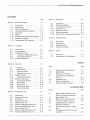
- - - - - - - - - - - - - - - - - - - - - - - - - - - List of Contents/Tables/Illustrations
CONTENTS
Page
Section 1
1-1
1-4
1-6
1-9
1-11
1-14
1-16
1-18
1-20
Section 2
2-1
2-3
2-5
2-6
2-8
2-10
Section 3
3-1
3-3
3-5
3-7
3-9
3-12
3-21
3-24
3-26
.3-28
3-36
3-40
General Information
1-1
Introductio n
1-1
Specifications
1-1
Safety Considerations
1-1
Instruments Covered By Manual
1-1
Description
1-1
Options
1-2
Equipment Required But Not Supplied . 1-2
Equ ipment Available
1-2
Recommended Test Equipment
1-2
Installation
2-1
Introduction
Initial Inspection
Preparation For Use
Installation in 8080A Mainframe
Operating Environment.
Storage and Shipment
2-1
2-1
2-1
2-1
2-1
2-1
Operation
3-1
Introduction
Panel Features
Operator's Checks
Operating Instructions
Operator's Checks
I nitial Control Settings
Operating Instructions
Initial Control Settings
Normal Mode
Trigger Mode
External Gate Mode
Internal Gate Mode
3-1
3-1
3-1
3-1
3-1
3-1
3-3
3-3
3-3
3-3
3-4
3-4
Section 5
5-1
5-3
5-9
5-11
5-13
5-15
5-18
Section 6
6-1
6-3
6-5
6-8
Section 7
7-1
7-3
Adjustments
5-1
Introduction
Safety Considerations
Test Equipment Required
Alignment Tool
Performance Checks
Related Adjustments
Duty Cycle and Frequency Adjustments.
5-1
5-1
5-1
5-1
5-1
5-1
5-2
Replaceable Parts
6-1
Introduction
Abbreviations
Replaceable Parts
Ordering Information
6-1
6-1
6-1
6-1
Service
7-1
Introduction
Recommended Test Equipment
7-1
7-1
TABLES
Page
Table
1-1
1-2
4-1
6-1
6-2
7-1
7-2
Recommended Test Equipment
Specifications
Performance Test Record
Abbreviations for Replaceable
Parts List
Replaceable Parts
Reference Designators
Schematic Diagram Symbols
Performance Tests
4-1
Introduction
Equipment Required
Test Record
Repetition Rate Test
Trigger Output Test
External Trigger Mode (Slow) Test
External Gate Mode (Slow) Test
Manual Function Test
External Trigger Mode (Fast) Test
External Gate Mode (Fast) Test
4-1
4-1
4-1
4-1
4-2
4-2
4-3
4-4
4-5
4-5
1-1
4-1
4-3
4-5
4-7
4-8
4-9
4-10
4-11
4-12
4-13
6-2
6-5
7-1
7-2
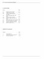
ILLUSTRATIONS
Page
Figure
Section 4
1-2
1-3
4-7
1-2
3-1
3-2
3-3
3-4
3-5
8081 A 300 MHz Rate Generator
Module and Supplied Accessories
Serial Number Plate
8081 A Controls and Connectors
Test Set for Operator's Checks
Suggested Equipment Setup for
Operating Instructions
Rate Generator Output in Trigger
Mode
Rate Generator Output in External
Gate Mode
1-0
1-1
3-0
3-2
3-2
3-3
3-4
List of Illustrations/Schematic Diagrams
ILLUSTRATIONS
Page
Figure
4-1
4-2
4-3
4-4
4-5
4-6
4-7
5-1
5-2
6-1
Repetition Rate Test Setup
Trigger Output Test Setup
External Trigger Mode (Slow)
Test Setup
External Gate Mode (Slow) Test
Setup
Manual Function Test Setup
External Trigger Mode (Fast) Test
Setup
External Gate Mode (Fast) Test Setup.
Duty Cycle Adjustment Test Setup
Frequency Adjustment Test Setup
8081 A Replaceable Parts .. ,
4-1
4-2
4-2
4-3
4-4
4-5
4-5
5-2
5-2
6-4
SCHEMATIC DIAGRAMS
Diagram
1
2
3
Page
Control Board A1
300 MHz Rate Generator Board A2
Distribution Board A3
7-9
7-11
7-12
SCREWS
CABLE
808TA
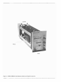
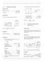
Figure 1-1. 8081 A 300 MHz Rate Generator Module and Suppl ied Accessories.
,-------------------------------SECTION 1
"--~----------------------
1-1
INTRODUCTION
1-2
This Operating and Service manual contains
information required to install, operate, test, adjust and
service the Hewlett-Packard Model 8081 A 300 MHz
Rate Generator module.
Figure 1-1 shows the module and accessories supplied.
This section covers instrument identification, description, accessories, specifications, and other basic information.
1-3
A microfiche version of this manual is available on 4 x 6 inch microfilm transparencies (order number on title page). Each microfiche contains up to 60
photo-duplicates of the manual pages. The microfiche
package also includes the latest Manual Changes supplement as well as all pertinent Service Notes.
1-4
GENERAL INFORMATION
is a significant change to the instrument. The last five
digits are assigned to instruments sequentially. The contents of this manual apply directly to the instrument
serial number quoted on the title page. For instruments
with lower serial numbers, refer to the backdating information in Section 8 of this module manual. For instruments with higher serial numbers, refer to the Manual
Change sheets at the end of this module manual. In addition to change information, the Manual Change sheets
may contain information for correcting errors in the
manual. To keep this manual as up-to-date and accurate
as possible, Hewlett-Packard recommends that you
periodically request the latest Manual Change supplement. The supplement for this manual is identified with
this manual's print date and part number, both of which
appear on this module manual's title page. Complimentary copies of the supplement are available from
Hewlett-Packard.
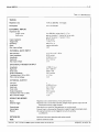
SPECIFICATIONS
HEWLETT - PACKARD
GmbH
[1536G00062 ]
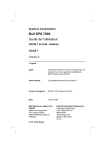
1-5
I nstrument specifications are listed in
table 1-2. These specifications are the performance
standard or limits against which the instrument is tested.
BOBLINGEN ..
Figure 1-1. Serial Number Plate
1-6
SAFETY CONSIDERATIONS
1-7
The Model 8081 A is a Safety Class 1 instrument (it has an exposed metal chassis that is connected
to earth via the 8080A system mainframe). This instrument has been designed according to international safety
standards and has been supplied in a safe condition.
1-8
This operating and service manual contains
information, cautions and warnings which must be followed by the user to ensure safe operation and to maintain the instrument in a safe condition.
1-9
INSTRUMENTS COVERED BY MANUAL
1-10
Attached to the inside of the instrument side
frame is a serial number plate (figu re 1-1). The first
four digits of the serial nu mber 0 nly change when there
1-11
DESCRIPTION
1-12
The Model 8081A is a 0-300 MHz Rate
Generator module designed to provide a clock source for
another 8080 system module. The 8081 A has four
operating modes:
Normal
Trigger
External Gate
Internal Gate
In Normal mode, the rate generator is free-running at the
repetition rate selected by the rate controls. In Trigger
mode, the rate generator is bypassed and the pu Ise
output is merely a shaped version of a pulse input from
either an external sou rce or a manual pushbutton. In
External Gate Mode, the rate generator output is gated
by a gate pulse from an external source or a manual
pushbutton. Internal Gate mode can only be useed with
an 8084A Word Generator module. The trigger slope
polarity and threshold level of external gate/trigger inputs is adjustable.
Mainframe is required. The 8080A mainframe provides
housing and power supplies for the 8081 A.
1-13
The power supplies for the 8081 A are provided by the 8080A Mainframe.
1-19
The 8081 A is one of a complete range of
rep. rate, timing and output modules that form the
8080 high frequency pulse generator system. Repetition rates range from 0-1 GHz and the modules are
interchangeabl e to enable you to purchase a system
exactly tailored to your requirements.
1-14
OPTIONS
1-15
The only option for the 8081 A Rate Generator is a second copy of the operating and service
manual which can be obtained by ordering option 910.
1-16
EQUIPMENT REQUIRED BUT NOT
SUPPLIED
1-17
To operate the 8081 A module, an 8080A
1-18
1-20
EQUIPMENT AVAILABLE
RECOMMENDED TEST EQUIPMENT
1-21
Equipment required to maintain the 8081 A
is listed in Table 1-1. Other equipment can be substituted if it meets or exceeds the critical specifications
I isted in the table.
Table 1-1. Recom me nded Test Equ ipment
Instrument
Critical Specification
Mainframe
Recommended Model
Used in
HP 8080A
Performance Tests,
Adjustments
Electronic Counter
up to 350 MHz frequency
HP 5345A
Performance Tests,
Adjustments
Sampling Oscilloscope
> 300 MHz bandwidth;
HP 182C with
HP 1810A plug-in
Performance Tests,
Adjustments
up to 200 mV/div sensitivity;
up to 0.5 ns/div sweep speed;
50 ohm input impedance
Real Time Oscilloscope
up to 1 MHz bandwidth;
up to 1 V/div sensitivity;
up to 10 Ils/d iv sweep speed;
four input channels
HP 182C with
HP 1804A and
HP 1821 A plug-ins
Performance Tests
Oscillator
up to 10KHz frequency;
up to 1 V RMS amplitude;
50 ohm output impedance
HP 651 B
Performance Tests
Pulse Generator
up to 250 MHz frequency;
2 ns pulse width; 0.5 V
amplitude; positive-polarity;
50 ohm output impedance;
square wave facility.
HP 8082A
Performance Tests
50 ohm Feedthrough
Termination
HP 10100C
Performance Tests
50 ohm Tee Connector
HP 1250-0781
Performance Tests
Model 8081A - - - - - - - - - - - - - - - - - - - - - - - - - - - - - - - 1 - 3
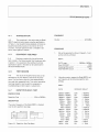
Table 1-2. Specifications
TIMING
Repetition rate:
10 Hz to 300 MHz in 8 ranges
Period jitter:
~
0.1 % ± 50 psec
EXTERNAL INPUTS
Repetition rate:
Trigger mode:
Gate mode:
Input impedance:
Trigger level:
Sensitivity:
Slope:
Max. input voltage:
o to 300 MHz, pulse width;;;' 1,7 ns
gate on duration> 1 period of int rep rate,
gate off duration> 1 period + 10 ns
50 n typical
-lV to + 1 V
200 mV p-p
neg/pas selectable
±6V
INTERNAL GATE INPUT
Gate duration:
Input impedance:
Amplitude:
High level:
Max input voltage:
on> 10 ns, off> 20 ns
50 n typical
~ 500 mV p-p
OV±100mV
±lV
EXTERNAL TRIGGER OUTPUT
Amplitude:
High level:
Duty cycle:
Output impedance:
Transition time (10% to 90%):
Max. external voltage:
~
500 mV p-p
OV ± 100 mV
50% ± 10%
50
~
n typical
1.2 ns
±2V
INTERNAL OUTPUT
Fan-out*:
Amplitude:
High level:
Duty cycle:
Output impedance:
Transition time (10% to 90%):
Max. external voltage:
1
~
500 mV p-p
OV ± 100 mV
50% ± 10%
50
~
n typical
1.2 ns
±2V
OPERATING MODES
Norm:
External trigger:
External gate:
Internal gate:
Manual:
OPTION 910
SIZE
Repetition rate is determined by front panel controls.
Repetition rate is controlled externally. Shaped input signal is output at both
internal and external trigger outputs.
Gate signal turns repetition rate generator on synchronously.
External input is disconnected. Generator is gated through internal gate input.
All external functions can be triggered manually by pressing
a pushbutton.
Add itional instrument operating and service manual.
Quarter mainframe width
* Fan-out: max. number of 8080 system modules which can be driven
UPDATE A NOV 76
. - - - - - - - - - - - - - - - - - - - - - - - - - - - - - SECTION 2
INSTALLATION
2-1
INTRODUCTION
2. Remove the upper two feet from the rear
of the BOBOA mainframe.
2-2
This section provides installation instructions for the Model BOB1 A 300 MHz Rate Generator
module. It also includes information about initial inspection and damage claims, preparation for use, and packaging, storage and shipment.
2-3
3. Remove the 80BOA mainframe top cover.
4. Insert the BOB1 A in the required position in the BOBOA mainframe (there are no
electrical limitations on the position).
INITIAL INSPECTION
2-4
Inspect the shipping container for damage. If
the container or cushioning material is damaged, it
should be kept until the contents of the shipment have
been checked for completeness and the instrument has
been checked mechanically and electrically. The contents of the shipment shou Id be as shown in Figure 1-1.
Procedures for checking the electrical operation are
given in Section 3. If the contents are incomplete, if
there is mechanical damage or defects, or if the 8081 A
does not pass the operator's checks, notify the nearest
Hewlen-Packard Sales/Service office. If the shipping
container is damaged, or the cushioning material shows
signs of stress, notify the carrier as well as the HewlettPackard office. Keep the shipping materials for carrier's
inspection. The HP office will arrange for repair or replacement without waiting for claim settlement.
2-5
PREPARATION FOR USE
2-6
Installation in 8080A Mainframe
5. Secure the 80B1 A to the 8080A mainframe using the two screws provided.
6. Connect the internal coaxial cable from
the 8081 A to the word generator, delay,
output amplifier modules or to remote
equipment as required. Connections are
Internal Output and Internal Gate. A connecting cable for the I nternal Output is
supplied.
7. Replace the BOBOA mainframe top cover.
B. Replace the two feet on the rear of the
8080A mainframe.
2-8
Operating Environment
ICAUTION]
The following installation procedure must
only be carried out by qual ified service personnel.
2-9
The 8081 A will operate within specifications
when the ambient temperature is between OOC and 55 0 C.
2-7
To operate the BOB1 A, it must first be installed in an BOBOA Mainframe as follows:
2-10
Storage and Shipment.
2-11
The BOB1 A can be stored or shipped at tem-
1. Switch the mainframe LINE OFF/ON
switch to OFF. Disconnect the power supply
cable from the rear of the 8080A mainframe.
peratures between -40 o C and 75 0 C. The instrument should
be protected from temperature extremes which cause condensation within the instrument.
If the instrument is to be shipped to a
Hewlett-Packard Sales/Service Office, attach a tag showing owner, return address, model number and full serial
number and the type of service required. The original
shipping carton and packaging material may be re-usable
but the Hewlett-Packard Sales/Service office will also
provide information and recommendations on materials
to be used if the original packing is not available or
re-usable. General instructions for re-packing are as follows:
2-12
1. Wrap instrument in heavy paper or plastic
2. Use strong shipping container. A doublewall carton made of 350-pou nd test material
is adequate.
3. Use enough shock-absorbing material (3
to 4 inch layer) around all sides of instrument to provide firm cushion and prevent
movement inside container. Protect control
panel with cardboard.
4. Seal shipping container securely.
5. Mark shipping container F RAG I LE to
encourage careful handling.
6. In any correspondence, refer to instrument by model number and full serial number.
(
RATE
VERNIER
-"'1:---
• --NHI.-
-k.ti::r300-100-10'" • -100-10 - 1 -100 - 10
1
2
. 3 3 - 10 • 1 - 1· 10 - , - 1 ~ 10-\00
PERIOD
_iii_iii
NORM TRIG
3
====="~=
5.. ~AN
EXT INPUT
G)
G
o
GATE !
EXT
tNt
o
@
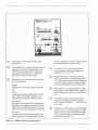
NORMrate generator free-running at selected repetition
rate.
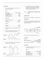
Figure 3-1. 8081 A Controls and Connectors
4
=
EXT INPUT LEVEL control: determines the
threshold voltage of the external trigger input.
Adjustable from -1 V to +1 V.
NEG-POS-MAN switch: for selecting the slope
polarity and/or source of external trigger signals.
In the POS and NEG positions, signals are appl ied
via the EXT INPUT connector. In the MAN position, the MAN pushbutton is used as the trigger.
MAN pushbutton: for generat;ng external trigger
signals when in TRIG and EXT GATE modes. The
NEG-POS-MAN switch must be in the MAN position.
TRIGrate generator output is shaped version of input.
Input is either via the MAN pushbutton or an
external signal into the EXT INPUT connector.
INT GATEexternal input is disconnected. Gate signal is provided internally by the word generator module and
6.
.,v
turns the rate generator on synchronously. Repetition rate as selected on the rate controls.
Mode switch: for selecting the mode of operation
of the rate generator:
EXT GATEgate signal turns rate generator on synchronously.
Repetition rate as selected on rate controls. Gate
'iignal either via the MAN pushbutton or the EXT
INPUT connector. Max. gate frequency 150 MHz.
/::'~
, . . .,
-IV
TRIGGER OUTPUT(-)
RATE switch: for selecting the range of pulse
repetition rate.
Rate VERNIER: for continuous adjustment of the
repetition rate within the range selected on the
RATE switch. Clockwise rotation increases the
pulse period (reduces the rate). In TRIGGER
mode, the rate controls have no effect.
'f)(T tNPU1 l.fVEL
EXT INPUT connector: DC coupled input to
which external trigger/gate signals are applied.
Input impedance is 50 ohms.
Maximum input
level ;s ± 6V.
(~)
TRIGGER OUTPUT connector: provides negative
output pulses in all modes of operation. In TRIG.
mode the output pulses are related to the trigger
input and not the repetion rate generator. Maximum external voltage ;s ± 2V.
SECTION 3
' - - - - - - - - - - - - - - - - - - - - - - - - - - - - - OPERATION
3-1
INTRODUCTION
3-2
This operating section explains the function
of the controls and connectors and describes the operators checks and typical operati ng modes of the 8081 A
300 MHz Rate Generator module.
3-3
Panel Features
3-12
J
Initial Control Settings
SOSl A:
1 RATE range switch
2 Rate V ERN I ER
3 Mode switch
5 NEG-POS-MAN switch
300-100 MHz
CCW
NORM
MAN
Oscilloscope:
3-4
Front panel controls and connectors are
shown in figure 3-1. Description numbers match the
numbers on the illustration.
3-5
Operator's Checks
3-6
Use the Operator's Checks (paragraph 3-91
to verify that the SOSl A is functioning correctly. The
SOSl A must be installed in an SOSOA Mainframe for
these checks. Thus it is important to remember that any
fault that is found may be in the BOSl A Rate Generator
or the 80S0A Mainframe. If the mai nframe is suspected,
carry out the SOSOA Performance Checks.
3-7
100mV/div
Channel A
EXPANDED, 1ns/div
3-13
The repetition rate of the output should be
approximately 300 MHz.
3-14
Turn the rate VERNIER 2 fully clockwise.
The repetition rate should be approximately 100 MHz.
3-15
Repeat repetition rate checks for RATE
ranges 100-10 MHz and 10-1 MHz at the CCW and CW
positions of the rate VERNIER. The repetition rates
should be approximately as shown on the RATE range
switch.
Operating Instructions
3-8
The Operating I nstructions (paragraph
3-21 I consist of a number of procedures that explain in
detail the function of each of the 80S1 A controls. All
operating modes are described. However, 1nternal Gate
mode can only be used if an 8084A 300 MHz Word
Generator module is avai lable.
3-9
Sensitivity
Trigger
Timebase
OPERATOR'S CHECKS
3-10
The test set for the Operator's Checks is as
shown in figure 3-2. The 8081 A Rate Generator module must be mounted in an S080A Mainframe.
3-11
Set the LI NE switch 9 on the 8080A Mainframe to ON.
3-16
Switch off the oscilloscope. Replace the
oscilloscope sampling plug-in with real time dual channel
vertical and timebase plug-ins. Reconnect the TRIGGER
OUTPUT 8 to the channel A input and switch on the
osci Iloscope.
3-17
Repeat repetition rate checks for RATE
ranges 1 MHz -100 KHz, 100-10 KHz, 10-1 KHz,
1 KHz-l00 Hz and 100-10 Hz at the CCW and CW
positions of the rate VE RN I ER. The repetition rates
should be approximately as shown on the RATE range
switch.
3-18
Set BOB1A mode s'.'vitch 3 toTRIGand
press the MAN pushbutton 4 several times.
3-19
Output should go high when button is pressed and low when button is released.
8080A
MAINFRAME
RATE
VERN1£R
,--MH.--
-Hl-
-kH:r-
300-100-10 - 1 -100-10 - 1 -100 ... 10
1
J ~ - IU - I - • - I1J - , .
t - 11)-
ascI LLOSCOPE
WITH 1 GHz
SAMPLING PLUG-IN
iL'.l'J
P 'RIOI>
EXT INPUT LEVEL
GAlE
t~OR" HUG
EXT
INT
D
9
CH
A
50 OHM COAXIAL CABLE
Figure 3-2. Test Set for Operator's Checks
RATE
J --I\lH.-~O-100-'O
.
1
J J -
t
-
VERNIER
-kHl-
- 1 - toO -10 -
1 -
1 -
~[JI -
I -
-H.;z;-
.
~ -100 - 10
1 -'
2
·1
EXT H4PUT LEVEl
NQR,lOI TRIO
GAtE
EXT
fN:r
-,
NEG pOs
ro\AN---~~
OSCI LLOSCOPE
D
9
PULSE GENERATOR
-------0---0
DUAL
CHANNE L
VERTICAL
PLUG·I N
- - - - - 0- - - - - OUTPUT
500HM
TEE
50 OHM
COAXIAL
CABLES
Figure 3-3. Suggested Equipment Setup for Operating Instructions
L....-
TIMEBASE
PLUG·I N
EXT
INPUT
CH. -
o
CH.----'
A
B
00
3-26
3-20
Set BOB1 A mode switch 3 to EXT. GATE
and press the MAN pushbutton. The repetition rate
should start when the button is pressed and stop when
the button is released. When the button is pressed, i. e.
when the gate opens, the first pulse should always start
at the beginning. However, when the button is released,
i. e. the gate closes, the last pulse may be cut short.
3-21
3-27
In Normal mode, the repetition rate generator is free-running at the frequency set on the rate con·
trois. The pulse output is the same as on the oscilloscope
(the trigger output is identical to the pulse output). The
pulse duty cycle is 40-60%.
OPERATING INSTRUCTIONS
3-28
3-22
A suggested equipment setup for the Operating Instructions is shown in figure 3-3.
The B081 A Rate Generator must be mounted in an
BOBOA Mainframe. The following procedure is designed
to give a full understanding of the function of each of
the 8081 A operating modes.
Initial Control Settings
8081A:
8081A
CD
RATE range switch
~ Rate VERNIER
~ Mode switch
@ EXT INPUT LEVEL
@ NEG-paS-MAN switch
@ Mode switch
@ NEG-POS·MAN switch
1 MHz-100 KHz
CCW
NORM
+1 V
pas
Timebase
Trigger
TRIG
pas
Pulse Generator:
Switch pulse generator on.
Set pu Ise period to about 15 fJ.sec.
Set pulse width to about 8 fJ.sec.
Set pulse amplitude to 2V and polarity to
pas.
Set the oscilloscope to trigger from channel B internally.
Oscilloscope:
2 psec/div
Channel A internal
Pulse Generator: switched off.
3-25
modes:
Trigger Mode
3-29
In TRIGGER mode, the repetition rate of
the output is independent of the internal repetition rate
generator. The output is, in fact, a pulse-shaped version
of the input signal. The input can be either external via
the EXT INPUT (-j) or local using the MAN pushbutton ®. For external triggering, an external signal source
is required. The test set is as shown in figure 3-3. The
changes in control settings are as follows.
3-23
Set the LINE switch on the 8080A Mainframe to ON.
3-24
Normal Mode.
The 8081 A has four different operating
Normal (NORM)
Trigger (TRIG)
External Gate (EXT GATE)
Internal Gate (INT GATE)
EXTERNAL
INPUT
RATE
GENERATOR
OUTPUT
Ov
ov
3-30
The oscilloscope display should be as shown
in figure 3-4. The 8081 A output should only be
delayed on the external input by the internal circuitry
delay of the 8081 A
II
IIII
II
-L
-O.6V
f
L
I
---J !-fixed delay
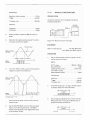
Figure 3-4. Rate Generator Output in Trigger Mode.
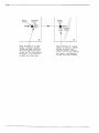
3-31
Vary the EXT INPUT LEVEL switch ® and
note that the trigger output disappears when the threshold level reaches approximately +0.2V. Set the external input level to -1 V.
3-32
Set the NEG-POS-MAN switch @to NEG.
Set the pulse generator output polarity to negative.
3-33
The oscilloscope display should be similar to
that shown in figure 3-4 except that the external input
is a negative-going pulse.
3-34
Vary the EXT INPUT LEVEL switch ® and
note that the trigger output disappears when the threshold level reaches approximately -O.2V.
3-35
As mentioned previously, the pulse output
in trigger mode can also be produced using the MAN
pushbutton ®. First set the NEG-POS-MAN switch ®
to MAN. This transfers the trigger input from the EXT
INPUT connector (J) to the MAN pushbutton @ . Set
the oscilloscope timebase to about 0.2 sec/em and trigger internally. Press the MAN pushbutton @ and note
that the pulse output goes high when the button is pressed and low when it is released. The EXT INPUT
LEVEL control ® has no effect in this mode.
3-36
External Gate Mode.
3-37
In External Gate mode the repetition rate
generator output is enabled/disabled by a gate signal.
EXTERNAL
INPUT
3-38
Set the Mode switch ® to EXT GATE. Set
the oscilloscope timebase to 2 usee/em and trigger internally. Press the MAN pushbutton and note that the rep.
rate generator runs at the selected rate for as long as the
button is held down.
3-39
Set the NEG-POS-MAN switch @ to POS
and the EXT INPUT LEVE L control ® to -1 V. Vary
the rate VERNIER C2>. Note that the last pulse may be
cut short by the gate turning off (see figure 3-5).
3-40
Gate off
Ov-------;
Last pulse may not be completed
Figure 3-5. Rate Generator Output in External Gate Mode.
Internal Gate Mode
3-41
Internal Gate mode can only be used if an
8084A 300 MHz Word Generator module is available. In
this mode of operation the gate pulse for the rate generator comes from the word generator via an internal connection. This gate enables the rate generator output in
the same way as an external gate. The purpose of this
mode is to enable an exact number of data bits to be
gated out of the word generator.
OV
Gate on
RATE
GENERATOR
OUTPUT
This gate signa I can come from either an external source (
via the EXT INPUT connector (J) or locally using the
MAN pushbutton ®. When the gate signal switches on,
the first output pulse is always started at the beginning.
When the gate signal switches off, the pulse is terminated
immediately, i. e. the last pulse may be cut short.
, . - - - - - - - - - - - - - - - - - - - - - - - - - - - - - - SECTION 4
PERFORMANCE TESTS
L--
4-1
EQUIPMENT
INTRODUCTION
4-2
The procedures in this section test the Model
8081 A's electrical performance using the specifications
of Table 1-2 as the performance standards. All tests can
be performed without access to the interior of the instrument. A simpler operational test is included in section 3 under Operator's Checks.
Counter
PROCEDURE
1.
4-3
EQUIPMENT REQUI RED
4-4
Equipment required for the performance
tests is listed in the Recommended Test Equipment table
in section 1. Any equipment that satisfies the critical
specifications given in the table can be substituted for
the recommended model.
4-5
HP 5345A
Set up the equipment as shown in figure 4-1 and
set the controls as follows:
8081A:
,
RATE range
Rate VERNIER
Operating Mode switch
NEG-POS-MAN switch
300MHz-l00MHz
CCW
NORM
POS
TEST RECORD
4-6
The results of the performance tests can be
tabu lated on the Test Record at the end of the procedures. The Test Record lists all of the tested specifications and their acceptable limits. Test results recorded at
incoming inspection can be used for comparison in
troubleshooting and after repairs or adjustments.
4--7
REPETITION RATE TEST
SPECI FICATION
Repetition Rate .,
10Hz to 300MHz
DESCRIPTION
The output frequency of the Model 8081 A is checked
over the full repetition rate range.
808lA
8080A MAINFRAME
o
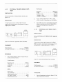
Figure 4-1. Repetition Rate Test Setup
2.
Using the counter, measure the Model 8081 A output frequency at the following repetition rate
settings.
8081A
RATE
VERNI ER RESULT
300MHz-100MHz
300MHz-100MHz
100MHz- lOMHz
100MHz- 10MHz
1OM Hz- 1MHz
10MHz- 1MHz
1MHz-100KHz
1MHz-100KHz
100KHz- 10KHz
100KHz- 10KHz
10KHz- 1KHz
10KHz- 1KHz
1KHz-100Hz
1KHz-100Hz
100Hz- 10Hz
100Hz- 10Hz
CCW
CW
CCW
CW
CCW
CW
CCW
CW
CCW
CW
CCW
CW
CCW
CW
CCW
CW
> 300MHz
< 100MHz
> 100MHz
< 10MHz
> 10MHz
< 1MHz
> 1MHz
< 100KHz
> 100KHz
< 10KHz
> 10KHz
< 1KHz
> 1KHz
< 100Hz
> 100Hz
< 10Hz
4-8
3.
TRIGGER OUTPUT TEST
Measure Ampl itude, Baseline and Duty Cycle.
SPECIFICATION
Baseline
,-.6V ± 50mV
to OV ± 50mV
50 % ± 10 %
Trigger Output Pulse
Duty Cycle
I-t J-t Off-J
on
DESCRIPTION
The trigger output pu Ise parameters are tested.
Duty cycle =
SAMPUNG
OSCI LlOSCOPE
80S1A
01
4-9
o
Figure 4-2. Trigger Output Test Setup
EXTERNAL TRIGGER MODE
(SLOW) TEST
The repetition rate output is controlled externally. The
trigger and internal outputs are pulse-shaped versions of
the trigger input.
HP 182C Mainframe
with 1810A plug-in
PROCEDURE
1.
x 100%
SPECI FICATION
EQUIPMENT
Sampling oscilloscope
ton
period
D
8080A MAINFRAME
6V ± 50mV
OV ± 50mV
50 % ~ 10 %
Amplitude should be . ,
Baseline should be
Duty Cycle shou Id be
Set up the equipment as shown in figure 4-2 and
set the controls as follows:
DESCRIPTION
The function of the Model 8081 A is tested in external
trigger mode using an external sinewave generator to
apply a trigger signal of 10KHz.
REI>,L TIME
8081A:
so OHM
OSCILI,OSCOP~
,
TERL4lNATlON
RATE range
Rate V ERN I ER
Operating Mode switch
NEG-POS-MAN switch
300MHz-100MHz
, .. ,
,
CW
NORM
POS
50QHM
Oscilloscope
Sensitivity .. ,
Trigger
Timebase mode
Timebase - direct
Timebase - expanded
2.
200mV/div
internal
expanded
20ns/div
2ns/div
Set Frequency to 100MHz on screen using Rate
VERNIER.
T£~
Figure 4-3. External Trigger Mode (Slow) Test Setup
EQUIPMENT
Oscillator
,
Real Time Oscilloscope
HP 651 B
HP 182C Mainframe
with 1804A and 1821 A plug-ins
50 Ohm Feedthru Termination
HP 10100C
/
5.
PROCEDURE
1.
Set up the equipment as shown in figure 4-3 and
set the controls as follows:
Set NEG-POS-MAN switch to NEG and repeat
steps 3 and 4 observing the pulses. The Model
8081 A output shou Id trigger on the negative
half-cycles of the oscillator output.
8081 A:
RATE range
Rate VERNIER
Operating Mode switch
EXT INPUT LEVEL
NEG-POS-MAN switch
100KHz-10KHz
CCW
TRIG
center
pas
4-10
EXTERNAL GATE MODE (SLOW)
TEST
SPECIFICATION
Gate signal turns rep. rate generator on synchronously.
Oscilloscope:
Sensitivity (both channels)
Trigger. ,
Timebase main
1V/div
external
20ps/div
Oscillator:
DESCRIPTION
The function of the Model 8081 A is tested in external
gate mode using an external sinewave generator to apply
a gate signal of 10KHz.
10KHz
1VRMs
Frequency
Amplitude
REAl. ,IME
OSCU.LOSCOPE
SQOHM
2.
Display oscillator output and Model 8081 A output
on screen
3.
Check that during the positive slope of the oscilla·
tor output a positive pu Ise output occurs.
TERMINATION
so OHM TEE
OSCILLATOR
OUTPUT
Figure 4-4. External Gate Mode (Slow) Test Setup
i*-- Propagation
delay
OUTPUT
4.
EQUIPMENT
I
8081A
Oscillator
Real Time Oscilloscope
Turn EXT INPUT LEVEL control from positive to
negative and observe waveforms.
, HP 651 B
HP 182C Mainframe
with 1804A and 1821 A plug-ins.
50 Ohm Feedthru Termination
HP 10100C
PROCEDURE
1.
OSCILLATOR
OUTPUT
Set up the equipment as shown in figure 4-4 and
set the controls as follows:
8081A:
8081 A
OUTPUT
Threshold lever""" +1 V
-1V
RATE range. ,
Rate VERNIER
Operating Mode switch
EXT INPUT LEVEL
NEG-paS-MAN switch
100KHz-10KHz
CCW
GATE EXT
center
pas
4-11
Oscilloscope:
Sensitivity (both cha nnels)
Trigger
1VIdiv
external
Timebase, main
20~s/div
MANUAL FUNCTION TEST
\
SPECI FI CATION
All external functions can be triggered manually by
pressing a pushbutton.
Oscillator:
REAL TIME
ascI LLOSCO~E:
Frequency
Amplitude
500HM
10KHz
1VRMs
2.
Display oscillator output and 8081 A output on
screen.
3.
Check that during the positive slope of the oscillator output a pulse burst appears.
HRMINATJON
SOS1A
SOBOA MAINfRAME
o
00
Figure 4-5. Manual Function Test Setup
EQUIPMENT
Threshold level
Real Time Oscilloscope
OSCILLATOR
HP 182C Mainframe
with 1804A and 1821 A plug-ins
OUTPUT
I
I
I
I
PROCEDURE
I
I
~ r--Delay of 1/2 period
8081A
OUTPUT
4.
i,hnnnn rl -----.lJ UUUUU~
1.
OV
Set up the equipment as shown in figure 4-5 and
set the controls as follows:
8081 A:
RATE range
Rate VERNIER
Operating Mode switch
EXT INPUT LEVEL
NEG-POS-MAN switch
Turn EXT INPUT LEVEL control from positive to
negative and observe the waveforms.
, .. ,
100KHz-10KHz
CCW
GATE EXT
,
MAN
Oscilloscope:
OSCILLATOR I
OUTPUT
I
Sensitivity
Trigger, ,
Timebase, main
-+ __ I_
I
I
I
I
I
I
I
I
I
I
I
I
8081A
OUTPUT~
IlJU
Threshold level --+ +1 V
I
I
~__~
I
I
I
I
I
I
I
I
2.
1V/div
internal
10IlS/div
,
Press MAN pushbutton. As long as the Man button
is pressed a pulse train should be visible
~MAN button--..J
I
11nJllUlJlJt:
pressed
I
_llll~11Ill·I.lml-UIJ/JINI.ll-
OV
-1V
3.
Note that the last pulse will be cut off as soon as
the gate closes.
5.
,
,
Set the NEG-POS-MAN switch to NEG and repeat
steps 3 and 4 observing the pulses. The 8081 A
output should be gated on the negative half-cycles
of the oscillator output.
Set the Operati ng Mode switch to T RIG. Press the
MAN pushbutton. As long as the MAN button is
pressed the output should be OV.
r-
MAN button~
pressed
I
4-12
Oscilloscope:
EXTERNAL TRIGGER MODE (FAST)
TEST
Sensitivity
Trigger
Timebase mode
Timebase - direct
Timebase - expanded
SPECI FICATION
Same as EXTERNAL TRIGGER MODE (SLOW), paragraph 4-9.
2.
Adjust the Model8081A EXT INPUT LEVEL
control to obtain a stable 50% duty cycle display.
3.
Each trigger pulse from the pulse generator should
release one output pu Ise from the Model 8081 A.
Check that the display has a frequency of
250M Hz.
OESCRI PTION
A high frequency test of the Model 8081 A external
trigger mode using an external pu Ise generator to apply a
trigger signal of 250M Hz.
SAMPLING
OSCILLOSCOPE
200mV/div
external
expanded
20ns/div
0.5ns/div
4-13
EXTERNAL GATE MODE (FAST)
TEST
SPECIFICATION
Same as EXTERNAL GATE MODE (SLOW), paragraph
4-10.
DESCRIPTION
Figure 4-6. External Trigger Mode (Fast) Test Setup
The maximum external gate frequency of the Model
8081 A is tested in external gate mode using an external
pulse generator to apply a gate signal of 150MHz.
EQUIPMENT
Pulse Generator
Sampling Oscilloscope
HP 8082A
HP 182C with 181 OA
plug-in
SAr,.lPLIfIlG
OSCII,.LOSCOPE
PROCEDURE
1.
Set up the equ ipment as shown in figure 4-6 and
set the controls as follows:
Figure 4-7. External Gate Mode (Fast) Test Setup
Pulse Generator:
Repetition rate
Pulse width
Amplitude
Polarity
250MHz
2ns
0.2 V
positive
EQUIPMENT
Pulse Generator
Sampling Oscilloscope
HP 8082A
HP 182C with 1810A
plug-in
8081A:
RATE range
Rate VERNI ER
Operating Mode switch
EXT INPUT LEVEL
NEG-POS-MAN switch
_
TRIG
center
POS
PROCEDURE
1.
Set up the equ ipment as shown in figure 4-7 and
set up the controls as follows:
Pulse Generator:
Oscilloscope:
Repetition rate
150MHz
Pulse width
square wave
Amplitude
0.2 V
Polarity ........................•.. positive
Sensitivity
Trigger
Timebase mode
Timebase - direct
Timebase - expanded
200mV/div
external
, .. expanded
20ns/div
5ns/div
8081 A:
RATE range
Rate VERNIER
Operating Mode switch
EXT INPUT LEVEL
NEG-paS-MAN switch
2.
Adjust the EXT INPUT LEVE L control for a
stable 150 MHz pulse presentation on the display.
3.
Observe that each external gate pulse releases two
8081 A pulses.
300MHz-l00MHz
CCW
GATE EXT
center
pas
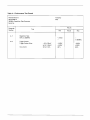
Table 4-1 Performance Test Record
Hewlett-Packard
Model 8081 A
300MHz Repetition Rate Generator
Serial No.
Results
Paragraph
Number
4-7
4-8
Tested by
Date
Test
Min
Repetition Rate
10Hz to 300MHz
Trigger Output
Trigger Output Pulse:
Duty Cycle:
-.6V ± 50mV
to OV ± 50mV
50 % ± 10 %
Actual
Max
<10HZ
-
-
> 300M Hz
-0.55V
-O.05V
40%
-O.65V
+0.05V
60%
,-------------------------------SECTION 5
'-----------------------------ADJUSTMENTS
5-1
INTRODUCTION
5-2
This section describes adjustments required
to return the Model 8081 A Repetition Rate Generator
to peak operating condition. Included in this section are
test setups, and checks and adjustments. Removal and
replacement procedures are given in the Disassembly/
Assembly procedure in section 7. An adjustment locator
diagram is included in this section.
5-3
SAFETY CONSIDERATIONS
5-4
Although this instrument has been designed
in accordance with international safety standards, this
manual contains information and warnings which must
be followed to ensure safe operation and to retain the
instrument in a safe condition (see Sections II and III).
Service and adjustments should be performed only by
qualified service personnel.
I WARNING
5-7
Make sure that only fuses with the required
rated current and of the specified type (normal blow,
ti me delay, etc.) are used for replacement. The use of
repaired fuses and the short-circuiting of fuseholders
must be avoided.
5-8
Whenever it is likely that the protection has
been impaired, the instru ment must be made inoperative
and be secured against any unintended operation.
5-9
TEST EQUIPMENT REQUIRED
5-10
Tabl e 1-1 contai ns a list of test equipment
and test accessories required in the adjustment procedures. In addition, the tables contain the required minimum specifications and a suggested manufacturer's
model number.
5-11
ALIGNMENT TOOL
5-12
A non-metallic alignment tool must be used
when making any adjustments to the Model 8081 A.
I
Any interruption of the protective
(grounding) conductor inside or outside the instrument
or disconnection of the protective earth terminal is
likely to make the apparatus dangerous. Intentional
interruption is prohibited.
5-13
5-14
After making the adjustments, carry out the
Performance Checks in Section 4.
5-15
5-5
Any adjustment, maintenance, and repair of
the opened instrument under voltage should be avoided
as much as possible and, when inevitable, should be
carried out only by a skilled person who is aware of the
hazard involved The opening of covers or removal of
parts, except those to which access can be gained by
hand, may expose live parts, and also accessible terminals may be live.
5-6
Capacitors inside the instrument may still be
charged even if the instrument has been disconnected
from its source of supply.
PERFORMANCE CHECKS
RELATED ADJUSTMENTS
5-16
The following adjustments must be performed in the order indicated in the procedures. The
adjustments can not be performed individually because
of interaction.
5-17
After making the adjustments the following
related adjustments should be checked. If the Model
8081 A output is connected to a word generator, the
word generator trigger level must be checked and, if
necessary, adjusted. If the Model 8081 A output is connected to an output ampl ifier, the output amplifier duty
cycle must be checked and, if necessary, adjusted.
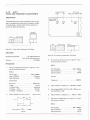
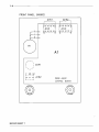
5-18
DUTY
CYCLE AND FREQUENCY ADJUSTMENTS
Duty Cycle
Frequency adjust
307M
9M
100M-10M 300M-100M
c:::J
CJ
c:J
R4
R8
R16
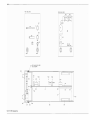
DESCRIPTION
08081-66502
BOARD A2
These adjustments set up the correct duty cycle at high
and low frequencies and cal ibrate the frequency output.
An oscilloscope is used to check the duty cycle and a
counter to check the frequency.
SAMPLING
OSCILLOSCOPE
8081A
8OS0A MAINfRAME
c::::J
D
cI
R109
o
80SlA
=
S080A
,
0
/,
=0
Figure 5-1. Duty Cycle Adjustment Test Setup
0
0
=
/
MA~NFRAME
//
/ , / ~/
/
;,-
/
/
,
COUNTE.A
/
///
//
/'
0
EQUIPMENT
HP 182C Mainframe
Sampling Oscilloscope
with 181 OA Sampl ing plug-in
HP 5345A
Counter
Figure 5-2. Frequency Adjustment Test Setup
3.
Set up the equ ipment as shown in figure 5-2 and
set the controls as follows:
PROCEDURE
80Bl A:
1.
Set up the equipment as shown in figure 5-1 and
set the controls as follows:
RATE RANGE
Rate VERNIER
Operating Mode
8081A:
RATE range
Rate VERNIER
Operating Mode
300-100MHz
Clockwise
NORM
Counter:
Frequency
Oscilloscope:
Sensitivity
Trigger
Timebase mode
Timebase - direct
Timebase - expanded
2.
200m V/d iv
internal
expanded
20ns/div
1ns/div
Adjust A2R16 for a duty cycle of .... 50 % ± 10 %
300-100MHz
CCW
NORM
350MHz
4.
Adjust A2R4 to a frequency of 307MHz ± .5MHz
5.
Set the Model 8081 A RAT Eta 100-1 OMHz. and
rate VERNIER to CWo
6.
Adjust A2R8 to a frequency of ... 9MHz ± .1 MHz
7.
Reconnect the equipment as in figure 5-1 and set
the controls as follows:
B081A:
Duty Cycle =
ton
period
x 100%
RAT E range
Rate VERNIER
Operating Mode
300-100MHz
CCW
NORM
8081A:
Oscilloscope:
Sensitivity
Trigger
Sweep Mode
Timebase - main
Timebase - expanded
RATE range
Rate VERNIER
Operating Mode
Input Polarity
EXT INPUT LEVEL
200mV/div
internal
expanded
20ns/div
0.5ns/div
8.
Adjust A2 R109 for a duty cycle of .. 50 % ± 10 %
9.
Connect an external pulse generator to the Model
8081 A EXT INPUT connector and set the controls
as follows:
,
300-100MHz
CCW
GATE EXT
POS
approx +0.5V
Oscilloscope: same settings as for previous adjustment (step 7).
External Pulse Generator:
Repetition Rate
50MHz
Operating Mode
square wave
Ampl itude . . . . . . . . . . . . . . . . . . . . . . . . . . . . 1 V
Polarity
positive
10.
Check the duty cycle of the first pulse on the display. If necessary, readjust Rl09 slightly to set the
duty cycle to
............................... 50% ± 10%
, - - - - - - - - - - - - - - - - - - - - - - - - - - - - - - - SECTION 6
' - - - - - - - - - - - - - - - - - - - - - - - - - - - R E P L A C E A B L E PARTS
6-1
INTRODUCTION
6-7
The information given for each part consists
of the following:
6-2
This section contains information for ordering parts. Table 6-1 lists abbreviations used in the parts
lists and elsewhere in the manual. Table 6-2 lists all
replaceable parts in reference designator order.
Table 6-3 contains the names and addresses that correspond to the manufacturer code numbers.
6-3
a. The Hewlett-Packard part number.
b. The total quantity (Qty) in the instrument. This is given only once for each part at the first appearance of the part in the list.
c. The description of the part.
d. A typical manufacturer of the part in a
five-digit code.
e. The manufacturers' code number for the
part.
ABBREVIATIONS
6-4
Table 6-1 lists abbreviations used in the
parts lists, schematics and elsewhere in the manual. In
some cases two forms of the abbreviation are used, one
all in capital letters, and one partial or no capitals. This
occurs because the abbreviations in the parts lists are
always all capitals. However, in the schematics and other
parts of the manual, the same abbreviations may have
upper and lower case letters.
6-8
ORDERING INFORMATION
6-6
Table 6-2 is the list of replaceable parts and
is organised as follows:
6-9
To order a part listed in the replaceable parts
table, quote the Hewlett-Packard part number, indicate
the quantity required, and address the order to the
nearest Hewlett- Packard office (list of Sales/Service
offices at the rear of the 8080A Mainframe manual).
a. Illustrated parts breakdowns for chassis
mounted parts.
b. Chassis mounted parts in alphanumerical
order by reference designator.
c. Electrical assemblies and their components in alphanumerical order by reference
designator.
6-10
To order a part that is not listed in the replaceable parts table, include the instrument model num·
ber, instrument serial number, the description and
function of the part, and the number of parts required.
Address the order to the nearest Hewlett-Packard office.
6-5
REPLACEABLE PARTS
6-4-----------------------------------------------------------------------------
FRONT PANEL (MP5)
FRONT PANEL (INSIDE)
MP1
R'O
A1S4
I[[IJ
Al
MP2
d
A1S3
lillJ
/
A1R1
A1S1
<©I
o
.... -
.......
(
\
; A1 Rl
/
r--,
MP6
C
NO
~o
•
NC
Al S2
01
l.- _ _ _
J
08081 • 66501
CON TROL
A1S2
@
/
MP11 {TAPE, ADHESIVE BOTH SIDES
TAPE, SCREENING
....I
MP 12
. '.
E
'l.-
~
I-
10
~
A1W2
A2
J6
A1W1
II
I
§
Ie:
r;r{
7
0 1
MP5
IT
h
~
lJ
('
.
C
Ir--A1
I
BJ
\
II
II
f-
P/OW2
Wl
II
f---
A1W2
+
•
A2
1
\
A2X2
P/OW1
i
+
I J7
IrR
~
L---..r&
~2
I
/2J1
/
A2X3/
A3X/
MP3/
I
-r----
A3 ------
10
I-
\
AIWl
A2
A2
J4(LOWER) J5(UPPER)
"'" MP3
.
MP7
l""I
P/OW2
Rl
\
o
P/O
:1
F igu re 6-1. 8081 A Replaceable Parts
(0
0)
P/OWl
PlOW 1
"'"
BOAR D
\MP 10
MPll
f
I
/
MPa
MP9
01
r---
MP 10
-----------------------------------6-5
Table 6-2. Replaceable Parts
~8D~l
~O::lIA
I~S[HJMt~T
F~
SERIOL PRU IX
h"1
'EF~~"NC~
Ut$IG~ATCR
Al
02
'3
MPl
nz
H-P PART
OESCRIPTIGN
~UM~ER
CijCUI-tt~CI
)9CEI-H5~2
3D
03091'005)3
to
ec
~31C-l(~L
KNOB
AY-CD~rpCL
AV-PATE
AY-MCT~EP
MP~
0)7(-1(0
04C3- Q 1t4
;E(ijl-((;",I
3101-0351
HCe
GLllJE PC
PANEL fRONT
UP PUSh dUTTOi
Mf 7
~<"'(
v-89 £ ~
146(\-1070
PANEL -SUB
!APE-INOL
,~P
3
MPb
"p II
P-VAR
CUL
10K
.7S~
5~
I_
AY-! NIL CUT
RATE
VE R\\I\ t.: R
6-6-------------------------------------------------------'--------Table 6-2. Replaceable Parts (cont'd)
MCr.H dOdt.
~COEl
fN5T~UM€NT
A
l;~SlJCUMtf\ll SE~
8C8U
I
l'8'J8t-6650 1
eo
H-P
Al
RI
ZI00-2492
R-~AR
AI
A1
AI
AL
Al
5I
5Z
53
53
54
31)I-IZZ1
C8C 15-~190,
:WI-15~B
5)"J-~~40
v~CI5-619J]
s. Sl IDE DPOT
5w PSTN SPCT
SlIDE AY
SP, [NC DE TEl'iT
SLIDE AY
~
54
5,)2J-~~loiO
SP~
I
~UMelR
RH"HNCE
~.: 5 1l>"<A TOF
A~-CO/VTROl
REFt.c NCE
OESIGNArOR
p~q
OESCR 1PTlCN
5K Zlll • s_
I NG DE TE ~ 1
INS T >J
~
,
M~NT
BO AY-RATE
REF~REac~
H-P PART
NUMeER
OESCRIPlI
A2
AZ
AZ
A2
A2
CI
CZ
C3
·1160-2,)55
;) 18()-CZ<;1
C~
C5
0180-C22"
~ 180-82ZS
(-F
C-F
C-F
C-F
C-f
.DIUF 100~
ILF 35V
IUF 35~
J3UF 10~
nuF I~V
A2
A2
A2
AZ
AZ
C"
C7
C8
CS
CD
G1 00-C229
') tBO-C<;~
0160-347C
OlfC-lE if
116('-1114
C-F
C- F
C-F
C-F
C- f
33Uf IUV
33uF IL\I
.LllU F 5JKV
47 PF ZO~~DC
• ~ 7UF 25V
AZ
AZ
AZ
AZ
A2
CII
CI2
CI3
.) 160- 24 ie
JI60-347"
o IH-3410
i) t60-34 70
1160-34 7·)
C-F
C-F
L-F
C- F
e-F
.01IJF
AZ
AZ
A2
AZ
AZ
CI6
C17
cIa
CI9
CZO
'I 16~-;4 i(
OloO-347C
.01\JF 50KV
.0IUF 5JK~
(116J-3716
Q18t-1735
C-F
C- F
C-F
C- f
C-F
.OUUf
.22UF 3,~
AZ
AZ
AZ
A2
AZ
C 21
~18o-01S7
34,(
C-f
C-F
C-F
C-F
C-F
2.ZVF 20~
22\Jf 15\1
22,1UF lOt L)~
.IlIUF IOO~
• DIUF 50K~
A2
A2
AZ
AZ
AZ
CZ"
C27
C2B
o 10C- ZC~ 5
Olfa-H7:
018()-1704
016Cf-34)0
~' 160-347(1
L-F
C-F
C-F
C-F
C-F
.0IOF l\1(1~
.0IUF 5uK~
47uF 6~
• (!IUF 50K~
.'110F 50KV
AZ
AZ
AZ
AZ
A2
CH
OZ
C 33
C34
J 16J-20~5
JI61-Z'155
016C-ZHI
JI6 )-34 iC
J 18"'1-')045
C-fC-F
C-F
C- F
C-F
.01uF IJO~
.0lUf ICO~
15PF 50M
.0IOF 50K~
ZOUI' Z5~
AZ
Al
A2
AZ
07
CH
C41
Ob
(I180-JJ45
J180-J045
C'18C-(045
016\'-17«,
C-F
C-f
C-f
C-F
2.\'UF
1901-,C5C
1901-)(} 5(
ISO I-C,,"O
010 51 ijJ~ .24
010 5 I 8v~ • ZA
CIG S r .OSA 3uv
nIl) S1 • \l5A 30~
OlD S [ .JSA 3(lV
DESIGNATOR
AZ
A2
AZ
Cl~
CI5
eLl
CZ3
C 24
CZ5
CZ~
C31
(35
))B\'-lZ~1
~l<O-C5q
o L<lo-C",E
1180-,208
016U-2C~5
o
I~O-
C~
50K~
5~K~
.(; lUF
• <'l OF
.0IUF
.) lUF
5()K~
;OK~
5')K~
15i)l'PF
20UF
'-,I)\)II
I j 'Z 5')
2~~
2S~
2C\JF Z 5\1
<,lUI' 6~
A2
CR I
CQ2
cn
CR4
CR5
1901-00<'11
AZ
AZ
(Ro
CR7
1901-0041"
1901-CC40
.(, to 51 • ~5A 30V
AZ
AZ
A2
A2
AZ
J<'
J5
J5
J6
J7
12 ~~-C €3~
IZ 50-COS
I dZC-0982
IZoO-C635
1250-0635
JACK ReCER 5TRAI
JACK .ECEP STRAI
IC AMPL llMIH~
JACK RECEP STRAI
JACK HCEP STRAI
AZ
AZ
AZ
LI
lZ
L3
nnO-1 f 1<,
9100-1614
SIDe-loll.
COIL COKE • Bl UH
COIL COKE .82 U~
cu [l CCKE 1.5 UM
AZ
I~OI-r,O<'C
010 S I
.O~A
30V
PA>T
DES CR I PT l,lN
REFERE;.CE
DESIGNATOR
~-P
A2
A2
t4
lS
9100-0341>
9100-n346
eO[L F XD
COIL FX 0
AZ
A2
AZ
AZ
AZ
L"
l7
16
L9
lI-)
9170-0029
9170-1:029
9110-00Z9
9110-()CZ9
9[,TQ-3147
FERR (lE 8EAO
FtRRITE 8EAO
FERRITE BEAU
FERRITE dEAO
COlt-F tlF 1')Uf
Al
A2
AZ
AZ
Ll4
LIS
Llo
lI7
'1100-3147
91vQ-3147
9100-;139
COll-F ~F IJUF
COlt-F liF I~UF
Cull INllUC 75U~
CO Il- F ~F 10UF
A2
AZ
AZ
AZ
AZ
AZ
AZ
AZ
AZ
A2
01
~2
03
04
o,l5
Nu~BER
~100-Jl41
Ido;-OZO~
IB 53-0Z 84
I 8~4- C215
1854-0392
1853-,1'186
185~-C~9l
Jo
Q7
OM
1853- 00,,6
ld54-039Z
010
Id53-0036
u<;
t85~-CZI5
.Z
AZ
AZ
A2
A2
y1L
OIZ
U13
1853-0.1)~
015
18'>3-003~
AZ
A2
AZ
AZ
AZ
<oll6
\117
OZO
OZI
02Z
Id53-0030
1853-(1036
185,3- oe36
1853-11036
AZ
A2
AZ
AZ
A2
Ol~
0,123
024
~25
026
Q27
lE53-0036
1>153-0036
1853- COb
IB~3-C036
X5TR-P~P
S I C~IP
X5TR-PNP SI C~IP
XSTR-PNP S I CHIP
XS TR-P~P 51 CHIP
XSTR-PNP ) I CHIP
XS TR-PNP
XSTR-P/vP
XS TR-P/vP
xsrR-p/vp
XS T R-PNP
SI
SI
SI
5r
SI
CHIP
CHIP
CHIP
CHI P
CHIP
S I PNP
5 [ PNP
XSTR
XSTR
XSTR
X51 R
XSTR
X5TR S I Nt'N
XS1 R SI NPN
X$TR 51 NPN
XSTR-PNP 5 ]
X51i< SI NPN
XSTR lN5i79 S I
<,)31
o,l32
03Q
1854-0Ll5
1854-(;ZI5
I >l54-C" 15
18;3-·1930
leS4-C2l5
A2
u35
185~-0345
51 NP/V
5 I NPN
S I /VP/V
C~IP
A2
A2
AZ
AZ
AZ
RI
RZ
R3
04
R5
3698-450 I
0757-0'43
Z100-3353
0"98-4<,Z4
R-F S~K It .12,W
R-F II n l .ll5_
R-F 1~.7Kll
.-~AR ZOK .5.
R-F I. 4K I' .125.
A2
AZ
AZ
AZ
AZ
~o
R7
R8
R'i
RIO
0757-CZ>l0
01>98-3156
ZIOC-3Z74
Of9B-44Z4
0757-0443
.-F !K It .125_ F
R-F 14.7K U
R-VAR IvK 10~
R-F 1.4KU .125\01
R-F lIKll .IZ5_
A2
RIl
0157-C43d
R-F 5.ltKlt
')6~8-4483
1E
IPT IUN
f\Ufo\i\EtI
~751-U1G
,-F 3. 10K I~
R-F 5.1 L~ 14
b25 I' • 12. Sw
,-F 825 I' • II Jrr
R-VAK L.)~ -.!<H
1<><;E- H55
")698-44,5
AZ
~L2
,)7,7-04Z\
R25
)6 sa-3444
•)157-041:>5
C757-(443
<-F 8Z'> 14 • J 2. 5".
R-F 316 IX .IZ5w
R-F JII> U • IZ 5.
~-F l(l":iKl:t .[l5•
k-f IIn1 • l25_
''157-C2ii::
to.-f
A2
AZ
A2
AZ
AZ
AZ
AZ
AZ
A2
A2
AZ
AZ
A2
AZ
AZ
A2
XSTR S I /VP~
XSTF< 51 PNP
xsrR s { NPN
XS TR 51 NPN
X5TR-PNP SI CHIP
IB03-0J15
1853-C015
H54- U LS
1854-0Z15
1854-C215
AZ
AZ
AZ
AZ
A<
028
OZ9
TRAI<5 I STUR
TRANSISTOR
X,TR 51 NPN
X5TK S I /VPN
XSTR S I PI"P
"~-RA
AL
A2
Al
AZ
AZ
AZ
AZ
4Z
Al
S E~ 1~l PR EF ])
no
IIISC~
RI7
,18
R 19
kl)
" ZI
AZ
AZ
A2
A2
AZ
C8C81-6650Z
P'~1
~Z
42
.2
A2
AZ
AZ
IA
e~::l,
1'12
PI.!
k14
PIS
> 16
AZ
AZ
AZ
~
H-P
AZ
.Z
A,
A2
AZ
~Z
MOll;:t b(
IAL PI< OF I X
'jtl ~cll- t:
5ER IAl PR EF I X
AZ
AZ
AZ
AZ
AZ
AZ
AZ
AZ
AZ
R23
Q24
J757-C~38
J757-C~,,1
'17 51-')4 ZI
Zln\l-334<;
069&-3~~6
J157-C~IZ
07~7-C4,1
l6<;8-3~~4
.-F
Q-F
"of
<-F
R-F
R-F
.!B3
.1&5
536
5J6
>lZ5
It .1251'1
It .IZ5~
I~ .IZ,_
It .125"
If .l25"
" Zc
'L I
Q2u
"Z'1
d698-H 7~
I
C6<;E-33H
<-F
'-F
'-F
R-F
"32
R33
CEI:-(CZ5
,)6SB-J378
(6S8-331M
C6~8- 33H
.'69B-4479
R-F IbU 5~ .Z5.
R-F 51 5~ .125.
.-f 51 ,~ .l~:iw
>-~ 51 5"
• 12 ~\tI
R-F 14KH .IZ5.
169>1-44 7~
C6St-<,4,S
J6~&-44 is
06G6-4479
O,,<;l-~~j<;
R-F 14KI(
R-F 14K 1 (
i<-F 14KI (
P-F L~K a
R-F 14n ~
0757-1424
07 57-~4Z4
(757- C4Z4
0757-.'424
015,-)4,,4
O-F L.IK I ( • U5.
R-F l.IKll .IZ 5.
Q-F I. IK I' • IZ5.
"-I' L.l~H • L25_
F-F I.IKI~ .125.
:qS7-~.c,24
C6<;O-~~21,
·~oS~-';;El
P-F
P-F
o-F
R-F
R-F
G6B3-~Z45
RS':'
:1683-8,45
,lvB 3-8Z45
_-F
_-F
R-F
I' 55
R5i>
0751-C3~~
')~ij;-d2it~
~-F
R- F
0, 0'- C42Z
R-F 909 1% • 115 ~
t, .IZ5.
~-F 9('9
I'-F 205 I ~ .IZ5~
R-F 3. ~IKI~
R-F I~KU .125_
>3J
r;}
~J';
p::
H.
RJ6
R37
K)d
"R41
3S
R41
R4Z
~43
R 44
R45
.46
047
.4~
R4~
R5J
~ ~1
.5Z
R53
.")157-C~~~
J~57-G43.t,
00B3->lZ45
C66:!- E2~S
k 57
P,58
R59
0751-0~22
R61
~1698-44
P,6Z
R63
k64
R65
R66
16<;e-~4;<;
()757-·)~2rl
~6J
06Sd-4418
C157- CZ73
7q
\lb~o- D 7b
0757-C27"
0157-0417
R-F
R-F
P-f
p-F
R-F
Znt .ll5. F
5. lin:;
14~ L(
• L23..3 .,,5~ll
51 5~ .IZ5~
• 1,5.
.125""
.125w
.125.
• l25w
I .I~ 11 .IL5.
l.o9KIl
150 5~ • IZ 5.
82JKH .25.
8Z0K;( • Z,W
8211K5t .25_
>lZ()K5t .25 "
~20jC;5'~ .25.
~ZllK51 .Z5 "
75 H • tZ 5.
14K It .12S.
15v U • IZ 5.
51 5% .IZ5W
3.16K I'
562 It .IZ5.
I<EFEOINCE
"E5 IG/VAT Uk
Il-P PAPT
UUC~
A,
AZ
A2
A2
AZ
< 67
RQO
R6G
GfSE- 4,25
J 15 7-1)~5.l
~-f
AZ
A2
AZ
A2
AZ
P7Z
P73
R74
R15
.Z
AZ
A2
AZ
AZ
~l
!dO
P7I
pn
R77
78
79
~
I'
P~0
,8 L
R~Z
1P I ION
~UM8ER
07S7-C"Zl l
0757-G;94
')6~8-blZ4
R-f
I. 54Kl4
,J .IK 11
R-F 15() H .1, sw
R-F 51. I U
R-f 187 14
R-F
R-F
R-f
R-F
R-F
15u S( olL5.
150 5t .IL 5.
5t .IZ5.
39 51 .IZ5.
; .30Kll
l6~~-32'>I
P-f
R-F
R-F
R-F
R-F
, . lC>K I(
2 KI' .125~ F
'dl l( • 125_
,,81 l ( .1l5.
365 U. .IZ ,~
)757-[l~IZ
R-F
R-F
R-f
K-F
R-f
juS U .IL5.
3d) 1( .IZ5~
14~ Lt .1l5_
14K\( .IZ5.
51 5~ .IZ5.
06S8-3lol
J6~8-3;PI
06<;8- 4l]J
OeSS-4IJO
96GB-3Z5d
l75 7-Cl d3
0757- t 41 ~
0" 7-0 .1"
0757-04lZ
)9
A2
AZ
'Z
AZ
R M3
Rli4
06<;8-):'46
OfGM-4,7"
R M6
C6SS- 337M
A2
AZ
AZ
AZ
AZ
~
C6q-3H~
R-F 51 ~~ .12,"
'-F ;1 5( • IZ 5.
~-f 51 ,f
R-f I. 6'>KI (
R-F 3. 3ZK U
AZ
AZ
AZ
AZ
A2
1'92
R93
"<;4
.95
R91>
v751-0~3]
A2
AZ
AZ
AZ
A2
). 97
R98
.9S
RIOO
Rl'31
P-F J. 3ZKL ~
R-F )1" I ( ~ 12:>...
R-F .. Q 2 U .IZ ~.
.-F IKlut • IZ 5.
R-f 11>2 I' • IZ5~
K-F 16, l ( • IZ'.
R-F l.01K I t
R-I' I .47KI t
R-F 1. LK 1; .125.
R-F 5.11KL~
AZ
AZ
AZ
AZ
A2
o<lOZ
RI03
1<104
Rl O~
Rl~v
A2
A2
AZ
A2
A2
RI07
plOd
"'109
RI \)
~ III
A2
AZ
AZ
A2
AZ
RIIZ
P 113
R II ~
R ll5
F< 110
AZ
AZ
AZ
AZ
R II 7
RIl6
RI19
RIZO
AZ
A2
AZ
A,
Po I, I
PA5
07
_88
R89
P 90
P9 L
J)6~8-4':'
79
00<;6-311rl
l,,9d-,J78
06S8-<,428
0707-0433
06S B- 3444
.)bC;8-44~d
0675-IOZ1
,1757-0405
01~7-\l405
0/57-0273
J757-IC9~
0757-04Z4
0757-043d
0757-043d
06S8-0/J8~
'l6SB-4428
) 157-v 422
00SB-4479
J757-0411
06se-~479
2100- 3 3~9
06SB-74b3
06S8- HII
06S>I-3;7~
J6S€-33H
0698-3111
0"<;8-517Z
OO<;8-~172
0757-C~38
0757-e~3a
01><;8-3376
00<;8- 337d
Ot<:a-
~4~3
·)6S8-340
;/757-J44C
~Z
RIZ 2
RIZ 3
R 1" ~
Rilb
AZ
A2
RIZ7
RIl8
00)-OS4
n57-04 In
C~S€-3,~8
,1757-0
)9~
.I".
R-F
R-F
R-F
R-F
R-F
'>.IIKU
t
1.6,iKU
'lOy I' .125.
14KU .IZ5.
2.1'>~1
R-f 562 1, .ll5w
R-F 14KU .12j""
R-VAR 100 -tiOl
R-f BZ LO t .U5.
R.. F 30 51 .IZ5_
Q-F
R-F
R-F
R-F
l(-F
08 5t .IZ5"
0>1 51 .125.
j() 5t .IZ5.
Il 5( .1l5.
13 5t • IZ 5_
R-F 5.11 KI"
R-f 5.II~H
R-F 51
.Ih.
R-F 51 5( .125.
,.
R-F
R-F
.- F
R-F
R-F
ZR7 1% .IZ5.
281 U .IZ5_
7. 5K I ~ .125.
4. C2KLt
51.1 U
R-F 51. I It
Q-F 30 I It • 125.
5. 5L1 DE SPOT
~2
51
~101-1341
AZ
A2
AZ
AZ
UI
L2
In
IC-DU~l
1(-OL~l
~Z
04
U6
1826-1111
1>126-(111
'.l81-3JI I
L6Z')-GZoS
AZ
AZ
VRIJ
vR II
1901-046('
C I C S I L;'j't/ .I5A
ole SI 15V .1!iA
AZ
.1
ijI5~-0( 05
_IRE 22GA w PV C
A2
XZ
xZ
.3
XJ
12CG-C <,7
12( ~- C 48
12C Cf-C , I
LOCK [IIP-IC
5CCKeT-IC
lCCK 01 P-IC
~uCKE T-IC
~2
AZ
~Z
lij5e-(01~
I~CI-CH(
12CC... ·:
~b
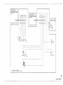
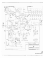
OP AMPl
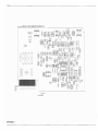
GP A~PL
lC DIG REP RATE
!C D[G TTL
ARRAY
);~TR
,------------------------------SECTION 7
L.....------------------------------SERVICE
7-1
INTRODUCTION
7-2
This section contains the component layouts
and schematic diagrams for the Model 8081A Rep. Rate
Generator. Tables listing the reference designators and
schematic symbols used are also given. Refer to section 6
for the replaceable parts information.
7-3
RECOMMENDED TEST EQUIPMENT
7-4
Test equipment and test equipment accessories required to maintain the Model 8081A are listed
in table 1-1. Equipment other than that listed can be
used if it meets the listed critical specifications.
Table 7-1. Reference Designators
A
B
BT
C
CP
CR
DL
DS
F
==
==
==
=
=
=
=
=
=
FL
=
HR
J
=
K
L
M
==
=
=
=
assembly
motor
battery
capacitor
coupler
diode
delay line
lamp
fuse
filter
heater
jack
relay
inductor
meter
U
P
==
==
Q
==
R
RT
S
T
TB
=
V
VR
W
X
Y
TP
==
=
=
=
=
=
=
=
=
=
micro-circuit
plug
transistor
resistor
thermistor
switch
transformer
terminal board
vacuum, tube, neon
bu Ib. photocell, etc.
voltage regu lator
cable
socket
crystal
test point
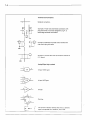
7-2 - - - - - - - - - - - - - - - - - - - - - - - - - - - - - - - - - - -
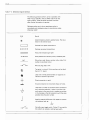
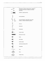
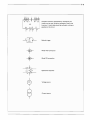
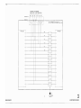
Table 7-2 Schematic Diagram Symbols
The following symbols conform, as far as possible, with
ANSI Y32.2, IEEE No. 315 and ANSI Y32.14 (for the
logic symbols). These standards should be consulted
when further information is required.
Resistance values are in ohms, capacitance values in
microfarads and inductance values in micro henries unless
otherwise noted!
PIO
Part of
*
Asterisk denotes a factory selected value. The value
shown is the nominal value.
[
---....,
_ _ _ -J
Encloses front panel nomenclature
Encloses rear panel nomenclature
Heavy line indicates signal path
- --90
Heavy dashed line indicates primary feedback path
Wire colour code. Same as resistor colour code. First
number is wire body colour.
Wire our plug used as link.
Test point ina circuit. Point may/may not be identified on P. C. board.
Used with trimmer potentiometers or capacitors to
indicate screwdriver adjustment.
Direct connection to earth.
.J..
Ground connection to instrument chassis or frame.
Used when a number of common-return connections
are at the same potential. If there is more than one
such system in the same circu it, numbers are written
in the triangles so that all connections with the same
potential have the same number.
I
xV
Specific potential difference with respect to a potential reference level, ego
I
+10V
Normally open toggle switch. Circles (0) are used for
the contacts to indicate a locking type switch.
/
--------------------------------7-3
Spring return, 2-position transfer switch. Triangles (A-)
'!re used for the contacts to indicate a non-locking
type switch.
o
9
9
o
6
6
)
.~
2-position, 2-pole slide switch.
Air cored inductor.
~.
II
Air cored transformer. The dot (e) is used, when
necessary, to indicate instantaneous polarity.
Iron core
If
Ferrite core
~ bead
Ferrite bead
---.l~
Varactor diode
~
Multi-junction diode
Diode
Zener diode
Schottky diode
Light Emitting Diode (LED)
Photodiode
Fuse
Neon
Filament lamp
7-4-------------------------------
Terminals and Connecton
Soldered connection.
Example of fixed male and female connectors with
plug and socket and contact designators, ego P. C.
board edge connector and socket.
example of bulkhead mounted coaxial socket with
free coaxial plug and cable.
example of coaxial cable with termination soldered to
P. C. board.
Analog/Digital logic symbols
,
~
2
3
2-input NAND gate
4-input NOR gate
Inverter
Flip-flop.
L
R
-
Q
6
The dynamic indicator denotes that this is a dynamic
input and operates on a transition, not a level.
-----------------------------------7-5
Complex functions represented by rectangu lar box.
Letters can be used inside the rectangle to clarify the
function. A truth table should be included, as close as
possible to the circuit.
U6
14
Schmitt trigger
+-
+
Wired AND connection
Wired OR connection
2
3
Operational amplifier
Voltage source
Current source
7-6------------------------------
Schematic
..--
--..,~
Signal
number
-~.
~
jr
)
Schematic
;;
~ number'
3
These references on a signal
leaving a schematic diagram
indicate the signal des1ination.
The circle contains the signat
number and the square contains
the numb er of the schema 1ic
to which that signal goes.
I
,I
6
These references on a signat
entering a SChematic diagram
Indicate the signal crigin.
The circle contain s the signal
number and the square conto'lns
the number of the schematic
on which that signal originates.
7-8 - - - - - - - - - - - - - - - - - - - - - - - - - - - - -
FRONT PANEL (INSIDE)
A1Wl
A1W2
r} •••••-il
:' A1J3
7
1
71
L!..
·1
1 4•-• -•-•8
o
Rl
A1
/---""
(
\
......
-/
C NO
~
A1R1
NC
,--\
I ••• 1
I'-
J
A152
08081 - 66501
CONTROL BOARD
(
SERVICE SHEET 1
--7-9
~~N~~~ BOARDI
..
I
I
W2
1
~:~
~~~i~-ARJ-~~-E-BOARDI: (~N177--k-<O:-~-_<;>_._y_I
(08081- 66502)
(OBOB1- 66502)
I
-10V
[II --.-1:WJ--~'-~+til~l
L.__
I
_
----
I
.
54
EXT
MHz
-'OV
Rl
INPUT
5K
LEVEL
-lOV
o
52
MAN. PUSHBUTTON
-10V
51
~
oNlels}~
0,
L A1 CONTROL
_ BOARD
_
(08081 - 66501)
----
1
CONTROL BOARD A1
7-10--------------------------------------------
300MHz RATE GENERATOR BOARD A2
08081-66502
FREQUENCY PGM
I5Il
~
•
•
WI
JUMPER
-1
~
CI.O
+
+
J1
COMPONENT
SIDE
CIRCUIT
SIDE
1
2
3
I.
5
6
7
8
A8COEFHJ
9
10
11
12
13
11.
15
KLMNPRS
Q
EMITTER·
COLLECTOR
BASE
(
SERVICE SHEET 2
7-11
A2 300 MHz RATE GENERATOR BOARD
108081-665021
~n
316
'."
fl."
UIDO'-;
[Jl!l
C6
33~
lR?6
[ )llK
Tca
10n
."
09
>K
-S.2\1
RI9
L1
.alp"
[6
[1
36
I
36[f.!.,
RJI
Sl
''''
[RH
Sl
R 20
j.1
536
,
3[9
8EAQ 38EAO ; [B
Rl1
~;"~
a
R31.
pi
38EAO
e19n,s,
rpll
LII
nn
'
U3
~
13
~
.
INTERNAL
[);~~
~7'.O4:
I
R1261
"I ~~' _,
~
I
-mr
-4
~J~6
,--
~
RH9
SI
ADJuST
Rl10
82
.l.
"I<J
- wt
PANEL
-
rk"r,t'.~ ~
;.i-J" :LL...C
....'
__
•
+-
f''J_+_-+--e"='''J-_-..,C.."loI'*C....
1
(3)
.I'n
JIll
'""5rr
~
S
W
,3·\
'I
i,oa08,.e~~~"
S2
pa"
1.'
:6"0
~R9S
:
m:~ ~
3.011'\
[~:"H +~i~
"
Q~lOl
'.IIK
---r],v
'
I
C1_l_J
+-__.
._~
.. _
CR11
029
&
i:~~
[ ;;~5
~
lIP
:X3
r"
0%Q1t-+-r---,
&
..
"sf
36\
b~»'t---+-----+
".---- ~-:7a -4,J
~:~
'2~
-t-t;
I'
-IOV
CONTROL BOARD
I
' 0
[ RIO'
'SI~
0
<>-
NEG R)S MAN
PIO Al CONTROL BOARDI
[
~
10&161- 6l)SOll
:
106061·E6S0n
'l-o·_12_B l
:
?;L
.J
1',:xJ)_'~_:_7~- --'.-.~ i
LO_2_'~~~'~~=~~~~A~~_~ I_~:~~~~~~~~~~~~~~~~~:~~~~~~~~~_._~_2_V __
i II U'Y-~81
I
1° )3 ':----P.-1~----A--1~----~
3 10
1L K
--
-~
i
6
I './
I
h'1!1.
r-r-
~ffi~~
'?\
l.LiK
'i\
~c;;.::
I
iQ
:.:~:
~'?~
025 ~.H-----Qr~R-'"--+/0lO ~
INtERNAL
1
.1. ~
---,.---------------l.--+~......!lr'
1OIK
'l-l'
ROO
R7,
-----,L--C26---,=+---I--- . '."
I
IOA1
ONTROl
BOARD
R1'
J9
-- '~X1l1
--~
'"
JJ'~,
L -.---------JCJ
l-=_
. d I
~
n;'j
)~,.~
I
~O'{j'
,
IWi"
Ui9K
~u"
!
-~
[ '1<81.
GATE' INPUT
GATE
·1.2v
3.31K
22
031
'5
ON WHEN
r:Y
llioK
~
~ ~~9 g:~II~~M
Xll{
11
en
°1'
(20 n U S l
.n""
,:,;
~9S
RB8
("'5189
5\
03',
In
a 35
REP RAT E GEt-IERA10A
l)S20K
~9<-,-~-R-,O-'-------..l-C-J-,-- '>ov
~
.l.
r
R~'
~-~-z~~R~a~-_
1
:
~OPfJl-±-----±----_.---~------
-- - -
-:1:----,-------·--1
~~~~~~~~~;g~:~B~g:~1
-----------------------------------1l:1l"'------~
lp/O A3 DISTRIBUTION
I
..
[P/O MAINFRAME
~OARD
'0808'- 665011
),),
\(
>()(
)(.\<)t
>()(
>( \ (
----....r-v-"'rv""V""'..rv-v-v-...~....,
DI~TRIBUTION BOA~Q
,080B0-66S0"
2
300MHzRATEGENERATORBOARDA2
7-12------------------------------------------------------------------------
MAINFRAME MOTHERBOARD
(POWER SUPPLY & PGM CONNECTIONS)
,r~A~
co MPONENT
cIRCUIT
GNO
SIDE
SIDE
--
-20V
-lOV
/
"
PGM
/1'
I
'---I
L ___ f---
NOT USED
-,i
/1'
~,
-52V
PGM
••/1'
'-----<
-- -
.1OV
GNO
-/~~r'-·7~1
"
L......-.
- ---- f----
I
LJi
--
A3 DISTRIBUTION BOARD
I
-
I-
2,
,,8
3
,C
i
- 5.2V
"
1
i
I
-IOV
I
'",
GNO
I
Ii
I
I
I
I
I
I
I
I
I
...
r
I
I
,
I
I
l
"
I
,
,N
/
I
I
l'
I
1
P
13"
I
/
I
'R
/
I
1
I
I
lSI'
I
I
Ii
i
I
I
I
I
!
,$
/
1
---100
",
.,,;;
I
I
I
I
I
1
K
I
12
i
i
iI
,M
11
I
I
I
J
9/
,
i
I
"
/
NOT USED
I
I
,
8",
10
I
I
,H
I
I
r
i
,F
7
i
/
6,
I
ii
,0
,
...
I
[
E
5
I
I
SERVICE SHEET 3
/
r
-IOV
--------~
I
, A
I
- 20V
I
I
I
I
I
1
GNO
I
I
(08081 - 665031
--~
I
I
~-
~-
IL
_
RATE GENERATOR
BOARO A2
A3 DISTRIBUTION BOARD