1
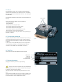
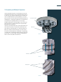
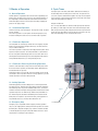
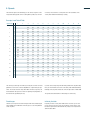
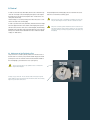
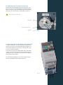
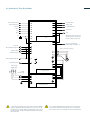
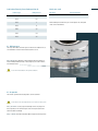
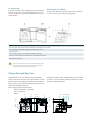
INDEX DRIVES, INC. Detroit, MI USA | Phone +1-313-366-1677 | Fax +1-313-366-8960 [email protected] | www.motionindexdrives.com Detroit, MI USA | Phone +1-313-366-1677 | Fax +1-313-366-8960 [email protected] | www.motionindexdrives.com March 2007, Februar 2007zet die agentur, HD INDEX DRIVES, INC. Operating Manual Rotary Index Tables RT INDEX DRIVES, INC. Contents 1. Safety Instructions 1.1. General Information 1.2. Validity of This Documentation 1.3. Use in Accordance with Regulations 1.4. Set-up 1.5. Transportation and Storage 1.6. Type Plate 1.7. Electrical Connection 3 3 3 3 4 4 4 4 2. Assembly and Mode of Operation 5 3. Modes of Operation 3.1. Normal Operation 3.1.1. Intermittent Operation 3.1.2. Continuous Operation 3.1.3. Continuous Reversing (Oscillating Operation) 3.2. Inching (Jog Speed) Operation 3.3. Emergency Stop 6 6 6 6 6 6 6 4. Cycle Times 6 5. Speeds 7 6. Control 6.1. Adjustment of the Positioning Cam 6.2. Minimizing Downtime 6.3. Optimizing Cycle Time Using a Second Cam 6.4. Optimizing Cycle Time Using Rotary Table Control TIC 6.5. Circuit Diagram TIC Three-Phase 8 8 9 10 10 11 7. Installation and Start-up 7.1. Installation 7.2. Start-up 12 12 12 8. Maintenance and Repair 8.1. Maintenance 8.2. Inspection 8.3. Repair 13 13 13 14 9. Spare Parts and Wear Parts 14 10. Malfunctions 15 11 Disposal 15 Symbols are as follows: Note / Attention Attention / Warning Danger of Electrocution Danger - Do not touch Danger - Advice must be followed Oil / Lubrication 2|3 1. Safety instructions 1.1. General Information Before you install and start operating this index table, please read these safety and operating instructions thoroughly. Also read all warning signs on the machine and make sure that they are not damaged and that they cannot be removed. Installation, start-up and care and maintenance may only be undertaken by qualified staff. People who are qualified in terms of these safety instructions are people who are familiar with the setup, assembly, start-up, operation and maintenance of index tables and who have appropriate qualifications. The safe operation of this machine depends on it being used according to instructions. Please keep these safety and operation instructions in an accessible place and give them to all people who have access of any kind to the machines. Should these instructions, and any others contained in this manual, not be observed, users and plant may be exposed to risks and damage to the equipment or serious injuries or even death could occur. Tips: This instruction manual was issued in January 2007. The information contained in this document is the property of MOTION Index Drives, Inc. and may not be copied, reproduced or given to third parties without express written permission. No liability is assumed with regard to the use of the information contained herein. Furthermore, the information contained in this manual can be changed without any prior notice since MOTION Index Drives, Inc. is continually developing its high-quality products and adapting them in accordance with new findings. All due care was used when creating this manual. MOTION Index Drives, Inc. assumes no responsibility for any mistakes or omissions; neither does the company assume any liability with regard to damage that may arise from the use of the information contained in this publication. CE certification is in line with the following standards: EEC machine guideline 98/37/EG EEC low-voltage guideline 93/68/EWG EEC guideline over the electromagnetic compatibility 89/336/EWG 1.2. Validity of this Documentation This instruction manual is valid for rotary index tables from the RT model range for the following sizes: RT 100, RT200, RT160, RT250, RT320, RT400, RT500 and RT630. The index table may only be operated after the entire system in which the index table is integrated, as well as the control and safety system, complies with the machine guidelines of the norms appropriate to the country where the table is set up and operated. Risk of crushing with rotating parts. Keep at a safe distance from moving parts! 1.3. Use in Accordance with Regulations The dimensioning of the rotary index tables is effected on the basis of the tables and calculations depicted in the brochure “Rotary Index Tables of the RT Model Range” and should be undertaken by technical salespeople from MOTION Index Drives, Inc. The appropriate accident prevention regulations as well as the otherwise generally acknowledged health and safety regulations must be complied with. Improper alterations and the use of replacement parts and additional devices not recommended by the manufacturer may result in injuries to staff or damage to property. Before working on the rotary index table and related tooling, switch the drive off electrically and make sure it cannot restart by itself! The rotary index tables described herein are intended for use in normal industrial plant. They may not be installed into machines and equipment whose failure could put human lives directly at risk or cause great losses. Not be used in an explosive environment. Any use of a rotary index tables where safety may be in doubt is not permitted! Please contact MOTION Index Drives, Inc. before using the index table in such an environment. 1.4. Set-up Rotary index tables must be set up in accordance with the regulations contained in the documentation. The installation position is user-defined, but it has to be disclosed to MOTION Index Drives, Inc. when ordering the rotary index table. Please check the completeness and correctness of the delivery before setting it up. Ring-eye bolts The following represents a portion of the scope of delivery: - The rotary index table - The documentation - The data sheet of the rotary index table - The instruction manual for the worm drive (option) - The instruction manual for the motor (option) - The instruction manual for rotary index table control TIC (Only if the control is part of the scope of delivery) Please verify that the type of rotary index table is correct by checking the type plate, see Figure 2. 1.5. Transportation and Storage In general, rotary index tables should be stored and set up in a clean, dry environment. When transporting, only use means of transport and hoisting gear that has been permitted for the weight of the rotary index table in question. In order to raise the rotary index table, please use two ring-eye bolts for size RT320, but three ring bolts for size RT400 and higher, which you screw into the screw thread of the output flange. (See Figure 1) Figure 1 1.6. Type Plate The following information can be gathered from the type plate: Manufacturer Model Size Serial Number Shop Order Number 1.7. Electrical Connection (Only applies if the drive is part of the scope of delivery) Any work on the electrical installation may only be undertaken by trained and qualified staff. Please observe all technical and country-specific regulations and norms during installation. Our rotary index tables are driven by three-phase brake motors as standard. Connect the motor and brake only to the power supply as specified on the type plate. The motors must be protected from overload by means of motor overload switches or other suitable protective devices. Figure 2 4|5 2. Assembly and Mode of Operation The rotary index table transforms a constant input drive motion into an intermittent output drive motion. The intermittent drive motion occurs by means of an inductively hardened and fine-milled barrel cam. The use of mathematical laws of motion guarantees a soft, shockproof and jerk-free movement that has been optimally designed for its intended purpose. The designed assembly allows for accurate and secure mounting to the output flange which is also free of play. No additional adjustment of the output flange is necessary. This can lead to mechanical over tightening and thus the rotary index table being destroyed in the long term. The power is provided either by means of a three-phase brake motor via worm drive or by means of a chain-wheel or belt wheel on the drive shaft of the rotary index table. This is firmly connected to the barrel cam, without any further internal gear sets, and it turns the cam followers and subsequently the output flange. The output flange is mounted within a wire bearing assembly, stiff and free of play (Within steel rings – not in the casting). The shaft seals appropriate for each size seal the rotary table off inside and out. Cam Follower Carrier Barrel Cam Figure 3 Dwell Phase Figure 4 Indexing Phase Figure 5 3. Modes of Operation 3.1. Normal Operation Normal operation is regarded as the movement of the output flange in a direction from one dwell position to the next. The rotational direction of the output flange is determined by the rotational direction of the drive. With a three-phase motor this can easily be reversed by swapping two phases of the supply voltage. 3.1.1. Intermittent Operation The drive shaft stops in the dwell phase. The step time is fixed. The dwell period is variable. This mode of operation is used in plants with much longer processing times than rotating times and is the most common mode of operation. 4. Cycle Times A complete cycle of the rotary index table is defined as the indexing of the drive flange from one dwell position to the next. The cycle time consists of the step time and dwell time together. The step time corresponds to the step angle of the cam and the dwell time corresponds to the angle without the cam gradient (see figure 6). Example: RT160-8-270 This is a rotary index table size 160 with 8 index points (8x45° drive flange rotation), a switch angle of the cam of 270° and a dwell angle of 90°. With an input revolution speed of 60 rpm and continuous input revolution speed, the rotary index table will execute 60 cycles per minute. The step time of the drive flange is 0.75s. The dwell time is 0.25s. 3.1.2. Continuous Operation The rotary table runs continuously without the motor stopping. Step and dwell times are fixed and run through continuously. The drive motor has only one rotational direction. This mode of operation is frequently used in high-production plants which require short processing times. The rotary index table is synchronized to the rest of the plant mechanically by means of a free drive shaft. The relationship between dwell and step time can be adjusted within certain limits by MOTION Index Drives, Inc. when producing the cam. 3.1.3. Continuous Reversing (Oscillating) Operation The drive of the index table is always reversed in the dwell phase. With this kind of mode of operation, the drive flange shuttles backwards and forwards between two positions. With rotation angles of less than 90° on the drive flange, the cam can be constructed in such a way that continuous reversing operation is possible without the direction of the drive being reversed. 3.2. Inching Operation With inching operation, the drive flange moves in small steps between two dwell positions. The barrel cam cannot gently accelerate and decelerate the built-up load. This puts the hardware under stress, since any acceleration that occurs during the inching operation exceeds that of normal operation many times over. Without any suitable rotary index table controls that allow gentle acceleration and braking of the load outside the dwell phase (in a way that is also kind to the drive), inching operation is not permitted. Please use our rotary index table control TIC. 3.3. Emergency Stop Emergency stop is comparable with the stopping in inching operation. Here, too, the stopping and re-starting of the built-up load occurs outside the dwell phase. Frequent emergency-stop situations should be avoided or should take place by using the rotary index table control TIC in such a way that there is no danger to the mechanism. Figure 6 0° cam gradient 5. Speeds 6|7 of inertia). The correlation is clearly laid out in the load tables of the “Rotary Index Table RT Model Range” catalog. The maximum speed of the drive flange, or the shortest step time of the rotary index table, depends on the resulting built-up load (mass moment Example: Load Table RT100 speed step 1 2 3 4 5 6 7 8 9 10 11 12 13 J 0,38 0,57 0,76 1,07 1,52 1,87 2,13 t 0,22 0,56 1,1 2,4 5,4 8,6 11,7 2,37 2,9 3,32 4,27 14,9 23,7 32 57 n 2 3 4 5 6 8 10 12 16 20 24 30 36 J 0,25 0,36 0,54 0,71 1 1,43 1,75 2 2,22 2,72 3,11 4 t 0,13 0,38 0,97 1,9 4,1 9,3 14,8 20,2 25,7 41 56 99 J 0,22 0,32 0,48 0,64 0,9 1,29 1,58 1,8 2 2,45 2,8 3,6 t 0,18 0,47 1,25 2,4 5,3 11,4 18 24,8 32,5 50 69 122 J 0,22 0,32 0,48 0,64 0,9 1,29 1,58 1,8 2 2,45 2,8 3,6 173 t 0,26 0,66 1,7 3,3 7 16 26 35 44 71 97 J 0,22 0,32 0,48 0,64 0,9 1,29 1,58 1,8 2 2,45 2,8 3,6 t 0,32 0,9 2,25 4,3 9,3 21 34 46 58 93 127 226 J 0,19 0,22 0,32 0,48 0,64 0,9 1,29 1,58 1,8 2 2,45 2,8 3,6 t 0,39 0,48 1,3 3,3 6,4 13,8 31,5 50 68 87 138 183 297 J 0,19 0,22 0,32 0,48 0,64 0,9 1,29 1,58 1,8 2 2,45 2,8 t 0,52 0,64 1,72 4,4 8,5 18,5 42 67 92 115 171 225 J 0,19 0,22 0,32 0,48 0,64 0,9 1,29 1,58 1,8 2 2,45 2,8 t 0,65 0,82 2,16 5,5 10,6 23 52 83 113 145 210 276 J 0,16 0,24 0,32 0,45 0,64 0,79 0,9 1 1,23 1,4 t 0,95 2,4 4,6 9 19 29 38 46 70 91 J 0,16 0,24 0,32 0,45 0,64 0,79 0,9 1 1,23 1,4 t 1,28 3,2 6 11,8 24 36 47 58 88 115 J 0,16 0,24 0,32 0,45 0,64 0,79 0,9 1 1,23 1,4 t 1,6 4,1 7 14 29 43 57 70 105 138 J 0,16 0,24 0,32 0,45 0,64 0,79 0,9 1 1,23 1,4 t 1,7 4,5 8,6 16 32 48 62 79 119 155 J 0,16 0,21 0,3 0,43 0,53 0,6 0,67 0,82 0,93 t 2,46 4,32 8,6 17 29 38 47 63 83 The shortest possible step time with any existing mass moment of inertia guarantees a service life of at least 30,000 hours of pure fixed-cycle operation. This means that for a rotary index table with a 0.5s step time, one would calculate 120 cycles for a minute of operating time (Regardless of the interval time specified by the use). If you can select a longer step time than that specified in the step time table, then you will extend the service life of the rotary index table dramatically. Doubling of the step time extends the service life by a factor of 200 to 500! Fixed Stages: Infinitely Variable: There are 4, 6 or 8-pole motors and worm gears with various reduction gear ratios available. The combination of the two gives us a sensitive gradation of the step times. Frequency Inverter or rotary index table control TIC allows you to conti nuously vary the step time. Please ensure that the 3-phase motors used have been optimized for 50Hz and that they clearly loose torque below 30Hz and above 60Hz. The speed can be altered either in fixed stages or continuously. 6. Control In order to control the rotary index table, the drive cam is fitted with a position cam. The length of the switching flag corresponds to the length of the dwell phase in the drive cam (Length of the 0° increase minus 2.5° safety area on both sides). The drive flange is in a securely locked position when the sensor is somewhere in the area of this switching flag. In order to synchronize the rotary index table, the brake and motor voltage have to be applied. The drive turns and the switching flag of the position cam leaves the sensor area. If the sensor is activated again, the drive flange, depending on the step angle of the rotary index table, will move to the next dwell position and the motor and brake have to be switched off. (Brake voltage off = brake active) Keep checking that the switching flag comes to a halt within the sensor area and is not left without a starting signal. If the control of this area is overridden by, for example, long processing times, the drive flange has moved too far and it could lead to a crash. Faulty motor contactors (jammed mechanical or burnt out electronic contacts) prevent the drive motor from being switched off. This could lead to severe personal injury or damage to property. Initiate an emergency stop immediately! 6.1. Adjustment of the Positioning Cam The position cam is secured in place by means of two frontal screws on the drive shaft. It is correctly set up when the feather key groove and the pointer points to the zero reference mark on the decal and the middle of the switching flag is positioned to the sensor. (See Figure 7) The grey area of the decal is only symbolic and does not indicate the length of the dwell phase. Correctly set up position cam. The zero reference mark on the decal, the pointer and the feather key groove point towards each other and the center of the switching flag of the position cam is at the sensor. Figure 7 8|9 6.2. Minimizing Time Losses Depending on the speed of the rotary index table, the dwell phase can be a few hundredths to several tenths of a second. If the drive is stopped right at the beginning of the dwell phase, you will lose, in the following cycle, the time the drive requires to carry out the rest of the dwell phase. Time-optimized control of the rotary index table means starting the external machining right at the start of the dwell phase (rising flank on the position sensor) and allowing the motor to turn for a short time for it to come to a standstill shortly before the end. (See Figure 9) To do this, you need either a second switch cam or rotary index table Controller TIC. WRONG! Stop immediately after identification of the rising flank on the position sensor. The entire dwell time is lost at the next start-up! Figure 8 RIGHT! Time-delayed switch-off. Ideal breakpoint at the end of the position cam. No time in the next cycle is lost! Figure 9 With continuous reversing operation always stop with the rising flank of the position sensor since the dwell phase is left again in the opposite direction. 2 1 Figure 10 6.3. Optimizing Index Time Using a Second Cam The Switch Cam can be adjusted by means of two frontal screws on the drive shaft. It has a short switching flag and gives the disabling signal for the drive. It should be set up in such a way that the position cam still safely activates the sensor with the end of its switching flag. (See Figure 11). The position cam must not be moved! Position Cam Delay for stopping the drive Switch Cam Figure 11 6.4. Optimizing Index Time Using Rotary Table Control TIC In a special “learning mode”, the rotary index table control autonomously measures the length of the switching and dwell phase and optimizes the switch-off plant independent of the speed of the rotary index table. In such a case, the second cam is redundant. At the same time, the TIC control enables different speeds, simple change of rotation, inching operation and a restart after an emergency stop from intermediate positions in a way that is does not tax the drive. An additional motor contactor can be eliminated. For more information regarding this control, please read the instruction manual for “TAKTOMAT Rotary Index Table controller TIC”. Figure 12 6.5. Schematic for Three Phase Model 10 | 11 Start in Automatic mode Position Reached Start in Manual mode Ready-to-Start Direction Programmable Cam Sensor Position Error Stop +24V Speed Warning! All outputs connected to inductive loads must be protected from overvoltage by using diodes. 0V PLC Cycle Time Error (flashing) Braking Voltage Error (always 1) Reset Error Monitor Braking Voltage VBR Wires to motor max. 20m long Operating Mode Measurement Cycle *!! ** Monitor Braking Voltage VBR 3~ External Brake Relay Power Supply 3x400V / 50Hz 1 3 5 E-STOP Customer Side 2 4 Frequency Inverter 6 Low-Frequency Filter *!! Warning! If using brakes with a supply voltage of 230VAC or 400VAC, a jumper is NOT allowed between MC and S2. In this case S2 must be connected directly to +24V DC. Braking voltage monitoring is then no longer possible. Hence we strongly recommend a 24V DC brake when using this Rotary Index Table. ** If a standard 230/400VAC three phase electric motor is interfaced to our single phase Rotary Index Table controller TIC, a Y-connection must be used. Please refer here to the description on the motor terminal block. 7. Installation and Start-Up Installation and start-up may only be undertaken by experienced specialists. Read the instruction manual. Also take note of the data in the other accompanying documents. Before working on the rotary index table and related tooling, switch the drive off electrically and make sure it cannot restart by itself! Any work on the electrical system may only be performed by specialists. Please comply with all technical and country-specific regulations and standards when carrying out installation work. 7.1. Installation Ensure that the mounting surface is flat. Clean mounting surface and apply an oil film. Mount the rotary index table onto mounting surface in installation position. Tighten fastening screws evenly. Mount alignment pins. Compare supply voltage with data on the rating plate. Connect motor and brake separately and with separately installed lines (Keep EMC in mind). Connect – see circuit diagram in terminal box. Adjust motor overload switch to the motor’s rated current. For data see motor’s rating plate. (Not necessary with TIC) Connect ground conductor to the motor’s grounding screw. 7.2. Start-Up Do not reach into the danger area. Check that the switch cam is in the correct position (See Figure 7). Remove all possible obstacles from the swivel range. Visually inspect the direction of rotation and reverse the polarity of the motor if necessary. Visually inspect the entire process. 8. Maintenance Maintenance includes inspection, servicing and overhauling. Maintenance work may only be undertaken by experienced specialists. Before working on the rotary index table and related tooling, switch the drive off electrically and make sure it cannot restart by itself! Lubrication Quantity (Installation position 6) Indexer Type Filling amount RT100 0,3l RT160 0,6l RT250 1l RT320 4l RT400 9,5l RT500 18,5l RT630 30l Lubricants used Oil (gears) Grease (bearings) Mobilgear XP460 Mobilux EP2 While handling these lubricants you consider please the safety data sheets of the manufacturer. 8.1. Maintenance The rotary index tables and worm gears on the drive are lubed for life as our standard for normal environment and conditions of use. Every month please lubricate using the bearing ring grease fittings on models RT400, RT500 and RT630. The bearing ring on smaller indexers are maintenance free. Do not mix mineral lubricants with synthetic lubricants. Figure 11 8.2. Inspection The intervals specified must be adjusted to suit the conditions. Switch the drive off electrically and make sure it cannot restart by itself! Every six months visually inspect for damage. Remove any deposit of dust (especially on the ventilation grille of the motor) and examine the electrical cables for damage. Every 12 months check the Rotary Index Table for play in the dwell positions. 12 | 13 8.3. Overhauling If the Rotary Index Table or drive is damaged, please contact MOTION Index Drives, Inc. first. Only an overhaul by MOTION Index Drives, Inc. ensures the agreed features. Any unauthorized opening of the casing will void the warranty. Replacing the cam followers The Rotary Index Table must be checked for play. If there is any play in one or more stations, the cam rollers have to be replaced. Turn input shaft (02) to the middle of the dwell. In the standard version, the grooves of the feather keys point upwards. Loosen long screws (25) from the four-point-contact bearing of the casing (Every second screw). In an upward direction, pull out the drive flange (13) with the ring-eye screws. Check cam followers Loosen the locking screws (16, 17) on the cam roller that has to be replaced Remove cam roller (15). Replace the damaged and the two neighboring cam followers. Re-assemble in reverse order All cam followers may have to be replaced. Check whether the mounting holes for the cam followers in the drive flange are still round and true to size. Alternatively, completely replace the drive flange. 9. Spare Parts and Wear Parts MOTION Index Drives, Inc. rotary index tables are practically maintenance-free. The cam followers do not cause any wear and tear on the hardened cam tracks; all roller bearings are oversized and run through an oil bath. For reasons of safety, only replacement parts which are of the same quality as the original parts may be used. When ordering, please give the following data: Model and order number , see type plate Name, see table below Quantity 13 12 10 14 Wear parts are marked (x). Please order replacement parts set. The quantity or amount n* of the cam followers and lubricants depend on the model and design of the Rotary Index Table. 14 08 20 21 19 18 22 01 09 26 15 07 06 05 02 Spare Parts and Wear Parts 14 | 16 Number Quantity Name Number Quantity Bezeichnung 01 1 Casing 14 (x) 1 Shaft Seal 02 1 Input Shaft 15 (x) n* Cam Follower 05 (x) 2 Shaft Seal 18 (x) 1 Four-Point-Contact Bearing 06 (x) 2 Groove Nut 19 (x) 1 Adjustment Ring for Four-Point-Contact Bearing 07 (x) 2 Tapered Roller Bearing 20 (x) 1 O-Ring 08 (x) 1 Groove Nut 21 (x) 1 O-Ring 09 1 Barrel Cam 22 (x) 1 Center Ring for Four-Point-Contact Bearing 10 1 Central Column 23 (x) 1 Shaft Seal 12 (x) 1 O-Ring 26 1 Housing Cover 13 1 Output Flange / Drive Flange n* Depending on Number of Indexes 10. Malfunctions Malfunctions Help Motor does not run - No supply voltage (check voltage) - Faulty motor contactor (replace) - Motor contactor switch activated (possibly allow motor to cool off and engage switch) - Brake not open (improperly connected or worn out) Motor turns but Rotary Index Table does not and the output flange has no play - Faulty worm gear (contact MOTION Index Drives, Inc.) - Torque limiting clutch has tripped (remove outside blockage) Motor turns but Rotary Index Table does not and the drive flange has play - Cam rollers broken off due to overload (contact MOTION Index Drives, Inc.) Motor runs with a loud humming noise - Motor runs on only 2 phases (check fuse or motor contactor. Measure current in all 3 phases – voltage measurement is not enough) 11. Disposal Lubricants (oils, grease) pollute the environment. Please dispose of them according to your local environmental regulations.