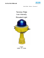
1
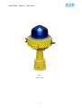
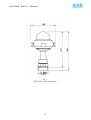
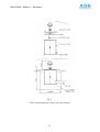
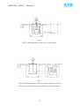
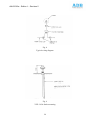
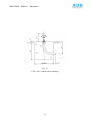
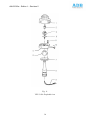
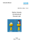
Instruction Manual
AM.03.320e – Edition 1 - Revision 5
Taxiway Edge
Low intensity
Elevated Light
Type
VEE - 3 - 030
AM.03.320e - Edition 1 – Revision 5
RECORD OF CHANGES
Rev.
Page
1
7
1
Checked
Approved
Changes to fig. 11
WM
WM
10
Polyurethane changed to aluminium alloy
WM
WM
1
11
idem
WM
WM
1
25
New parts numbers
WM
WM
1
37
page 37 cancelled and replaced by new 37
WM
WM
2
25
New CN for blue dome
WM
TRF
3
25
New parts numbers
DSE
DSE
Rebranding
EV
01/2010
New parts numbers
AES
05/2011
4
5
23
Description
1
Date
05/2000
AM.03.320e - Edition 1 – Revision 5
SAFETY INSTRUCTIONS
SAFETY PRECAUTIONS
The operating and maintenance personnel should refer to the maintenance procedures described
in the ICAO Airport Service Manual, Part 9, Airport Maintenance Practices and in FAA
Advisory Circular AC 150/5340-26 "Maintenance of Airport Visual Aid Facilities" for
instructions on safety precautions.
Personnel must observe the safety regulations at all times. While every practicable safety
precaution has been incorporated in this equipment, the following rules must be strictly
observed.
KEEP AWAY FROM LIVE CIRCUITS
Operating and maintenance personnel must at all-time observe all safety regulations. Do not
change lamps nor components or make adjustments inside equipment with the light circuit ON.
See FAA Advisory Circular AC 150/5340-26 concerning safety.
RESUSCITATION
Operating and maintenance personnel should familiarise themselves with the technique for
resuscitation found in the First Aid Instruction Manual.
2
AM.03.320e - Edition 1 – Revision 5
USE RESTRICTION NOTICE
This instruction manual is the property of
ADB
Leuvensesteenweg, 585
B-1930 Zaventem
Belgium
This manual or parts thereof may not be
reproduced, stored in a retrieval system,
or transmitted, in any form or by any
means, electronic, mechanical, photocopying,
recording, or otherwise, without ADB's
prior written consent.
3
AM.03.320e - Edition 1 – Revision 5
GUARANTEE
ADB guarantees that the performance of the inset lights described in this manual, when sold by
ADB or its licensed representatives, meets the requirements of ICAO Annex 14 volume 1 and
FAA specification AC 150/5345-46.
Any defect in design, material or workmanship, which may occur during proper and normal use
over a period of one (1) year from date of shipment, will be repaired or replaced by ADB free of
charge, ex works. Operational failure resulting from lamp burnt out, improper maintenance or
installation, damage due to runway maintenance equipment, snow ploughs or aircraft arresting
gear hooks is not considered a result of proper use and is beyond the scope of the warranty.
Warranty does not cover natural wear and tear nor damage arising after delivery owing to faulty
or negligent handling, excessive strain, unsuitable materials for Operation, deficient civil
engineering Work, unsuitable soil conditions, and such chemical, electrochemical or electrical
influences as were not assumed at the time of the Contract.
All liability for consequences of any inexpert alterations or repairs carried out by Purchaser or a
third party shall be waived.
ADB shall in no event be liable to Purchaser for any further claims, particularly claims for
damages not affecting the goods themselves.
The above constitutes the limits of ADB’s liabilities in connection with the inset lights covered
by this manual.
4
AM.03.320e - Edition 1 – Revision 5
TABLE OF CONTENTS
Page
SECTION 1
Record of changes
1
Safety instructions
2
Use restriction notice
3
Guarantee
4
Table of contents
5
List of illustrations
7
List of tables
7
GENERAL INFORMATION & REQUIREMENTS
1.1
INTRODUCTION
1.1.1
Purpose
1.1.2
Scope
1.2
DESCRIPTION
1.3
USE
1.4
EQUIPMENT SPECIFICATION DATA
1.4.1
Data
1.4.2
Performances
SECTION 2
9
10
MAINTENANCE
2.1
INTRODUCTION
2.2
LAMP REPLACEMENT
2.3
MAINTENANCE HINTS AND TIPS
17
2.4
PREVENTIVE MAINTENANCE
18
2.5
CORRECTIVE MAINTENANCE
19
2.6
SNOW REMOVAL
5
16
AM.03.320e - Edition 1 – Revision 5
Page
SECTION 3
3.1
SECTION 4
4.1
SECTION 5
TROUBLESHOOTING
TROUBLESHOOTNG GUIDE
22
PARTS LIST
PARTS LIST
23
INSTALLATION
5.1
INTRODUCTION
5.2
UNPACKING
5.2.1
Damage
5.3
INSTALLATION CRITERIA
5.4
BASE MOUNTING
5.5
STAKE MOUNTING
30
5.6
CONDUIT ELBOW MOUNTING
32
5.7
SETTING
33
6
24
26
AM.03.320e - Edition 1 – Revision 5
LIST OF ILLUSTRATIONS
Designation
Figure N°
Page
1
VEE-3-030
8
2
Typical layout
11
3
Outline dimensions
13
4
Photometric curve
15
5
VEE-3-030 mounted on a L-867 base duct system
25
6
VEE-3-030 mounted on a L-867 base trench system
27
7
VEE-3-030 mounted on a L-867 base
27
and the transformer in a pit, with cable duct
8
Typical wiring diagram
29
9
VEE-3-030 : stake mounting
29
10
VEE-3-030 : conduit elbow mounting
31
11
Exploded view
34
LIST OF TABLES
Designation
Table N°
Page
1
Ordering code
12
2
Equipment data
12
3
Equipment required but not supplied
14
4
Performances
15
5
Preventive and corrective maintenance tasks
20
6
Troubleshooting guide
22
7
Parts list
23
7
AM.03.320e - Edition 1 – Revision 5
Fig. 1
VEE-3-030
8
AM.03.320e - Edition 1 – Revision 5
SECTION 1
GENERAL INFORMATION AND REQUIREMENTS
1.1
INTRODUCTION
The VEE-3-030 fig. 1 Taxiway Edge Medium Intensity Omnidirectional Elevated
Light, is used to delineate the edges of airport taxiways, holding bays and aprons.
The VEE-3-030 is designed for either stake mounting conduit elbow mounting or
mounting on an L-867 base. The base mounting is advantageous from a
maintenance standpoint and provides added protection for equipment.
Stake mounted VEE-3-030 taxiway lights use transformers, cables and connectors
designed for direct ground burial.
1.1.1
Purpose
This manual describes procedures for the installation, maintenance, and
troubleshooting of the VEE-3-030 Taxiway Edge Medium Intensity
Omnidirectional Elevated Light.
1.1.2
Scope
This instruction manual covers equipment manufactured in compliance with FAA
specification AC 150/5345-46A, and ICAO Annex 14 for use as taxiway and apron
edge light; § 5.3.17.4 and with STANAG 3316 Ed. 7.
1.2
DESCRIPTION
The frame of the VEE-3-030 (Fig. 11) consists of a cast aluminium alloy frangible
stem (8) fitted with a 2" - 11 TPI thread on its base, on which a ball joint device (6
& 7) enable the setting and levelling of the optical system. The optical system is
composed of an upper and lower body (1, 5), the upper body (1) is a blue dome cast
in an aluminium alloy ring which covers completely the lamp holder up to the
lower body (5) providing like this water tightness without use of a gasket.
Two lateral thumbscrews and washers (10) secure the upper body on the lower
body.
The lower body, on its top part sustain the lamp holder secured by two screws, a
9
AM.03.320e - Edition 1 – Revision 5
lead assembly for connection of the lamp holder to the two-pole plug is secured on
the lower body by a strain relief bushing to avoid pulling on the connection to the
socket, and to help disconnecting the plug in case of impact.
The lower part of the lower body (5) is half spherical shaped adapted to the
polyester ball joint (6) sticked on the frangible stem. This knuckle-joint is locked
on the lower body, thanks to three screws (11) and a clamp (7) below the split ball.
This genuine knuckle-joint avoids the counter clockwise wires twisting problem
during installation and maintenance. The lower body and the ring of the blue dome
are made of an aluminium alloy.
A weakening groove is provided at the lower part of the frangible stem to eliminate
the need of a separate breakable coupling. Between the groove and the thread, an
hexagonal shaped part is provided to tighten or loosen the light unit from the
ground mounting device (base, conduit elbow, anchor stake).
All the aluminium castings are phosphatized and protected with an aviation yellow
electrostatic polyester powder coating. The lower body is fitted with a flag-holder
to locate the light with a flag in countries with heavy snowfalls.
1.3
USE
The ADB VEE-3-030 elevated light is designed for the lighting of Taxiway Edges
and Apron Edges serving Runways of all categories.
Fig. 2 shows typical layouts of the Taxiway Edge lights.
1.4
EQUIPMENT SPECIFICATION DATA
1.4.1
The ADB ordering code is given in Table 1 for the VEE-3-030. Reference data
pertinent to the equipment is listed in Table 2.
Information on items not supplied which might be required for installation is given
in Table 3.
10
AM.03.320e - Edition 1 – Revision 5
Fig. 2
VEE-3-030 : Typical layout for taxiway edge lighting
11
AM.03.320e - Edition 1 – Revision 5
Table 1
: VEE-3-030 - ordering code
VEE - 3 - 030
Taxiway Edge Light:
Omnidirectional:
Blue dome
Lamp wattage: 30W = 030
Table 2
: Equipment data
Type
: VEE-3-030
Input
: 6.6A
Lamp
: 30W/6.6A - EXL, quartz
Rated lamp life
: 1.000 hours
Temperature range of installation
: -55°C (-67°F) to +55°C (+131°F)
Humidity
: Up to 100%
Altitude
: Sea level to 3000 m
Wind
: Velocities up to 560 Km/h
Dimensions
: See figure 3
Net weight
: Approx. 1.2 kg
12
AM.03.320e - Edition 1 – Revision 5
Fig. 3
VEE-3-030: outline dimensions
13
AM.03.320e - Edition 1 – Revision 5
Table
3 : Equipment required but not supplied
Quantity
Description
1
Spanner 2" open ended
1
Ratchet, lever reversible (3/8") n° 435
1
Torque wrench (5-50Nm) n° 730/5 with
1
Square drive insert tool (3/8") n° 734/5
1
Socket n° 45a - 9/16 (3/8")
1
Water level
A/R
1
Loctite Grade AV or equivalent
T300/2 base plate assembly gasket and
Mounting screws (if base mounted)
1
L-867 base (if base mounted)
1
Anchor stake PA2 (if stake mounted)
1
Conduit elbow (if conduit mounted)
14
AM.03.320e - Edition 1 – Revision 5
1.4.2 Performances
The photometric performances are given in figure 4 and in table 4
Table 4 : VEE-3-030 Performances
Peak
Average
Beam spread
Beam spread
Intensity
Intensity
Horiz.
Vert.
Blue
5 cd
3 cd
360°
0° to 6°
Blue
5 cd
2 cd
360°
0° to 30°
Taxiway Edge
Colour
FAA L-861T
Taxiway edge ICAO
Fig. 4
VEE-3-030 - Photometric curve
15
AM.03.320e - Edition 1 – Revision 5
SECTION 2
MAINTENANCE
2.1
INTRODUCTION
Maintenance personnel should refer to the maintenance procedure described in the
ICAO Airport Services Manual, Part 9, Airport maintenance practices and in FAA
Advisory Circular N° AC150/5340-26, chapter 4, section 4.
The method of maintaining the VEE-3-030 Taxiway Edge Elevated Light consists
only of a light assembly servicing in the field, limited to cleaning of outer glassware
and to lamp and broken glassware replacement. If any lamp is out, the location of
the fixture should be recorded and the lamp replaced at a time when the circuit is
de-energized.
2.2
LAMP REPLACEMENT
De-energize circuit and lockout circuit.
Remove dome from fixture by loosening the two thumbscrews on the side of the
fixture. Pull out lamp. Wearing clean, white, lint free gloves insert a new lamp into
lamp socket and remove protective sleeving. Reinstall dome and tighten the two
thumbscrews.
16
AM.03.320e - Edition 1 – Revision 5
2.3
MAINTENANCE HINTS AND TIPS
2.3.1
Relamping
2.3.1.1
Make sure you are using the proper lamp.
Check P/N, watts and current as printed on lamp base.
Several aviation lamps of different ratings have the same outside appearance.
2.3.1.2
Never touch the quartz bulb with bare fingers.
Oil or grease may contaminate the surface of the bulb and in operation cause reduced
performance and premature failure. If the quartz is accidentally handled, clean before
operation with a cloth moistened with alcohol or methylated spirit.
2.3.1.3 It is a good precaution to check systematically the condition of the lamp holder and the
wiring at each lamp replacement. Signs of overheating are the result of poor
electrical contacts. The degradation process is fast if no remedial action is taken in
time.
2.3.1.4
Premature oxidation of lamp holder contacts in highly corrosive or salt-laden
atmospheres. In some cases the problem has been cured successfully by coating the
lamp pins and lamp holder contacts with a silicone jelly such as DOW CORNING # 4
COMPOUND or similar.
17
AM.03.320e - Edition 1 – Revision 5
CAUTION
Touching the lamp with bare fingers
may seriously shorten the lamp life.
If the lamp has been touched, clean
with tissue moistened with isopropyl
alcohol or methylated spirit.
2.3.2
Water
Build-up of condensation water in an elevated light is a normal process resulting
from the temperature and pressure differentials during the ON and OFF cycles of
operation. However the lights are so designed that condensation water will drain
away through the mounting stem and will be evacuated through one or two
purpose-made holes located near the shearing groove.
IT IS ESSENTIAL TO MAKE SURE THAT THESE DRAINAGE HOLES
REMAIN UNOBSTRUCTED
2.4
PREVENTIVE MAINTENANCE
Service life depends essentially on the respect of the preventive maintenance
procedures. Table 5-1 List the maintenance task to perform to maintain the
VEE-3-030 light operational at a maximum efficiency.
18
AM.03.320e - Edition 1 – Revision 5
2.5
CORRECTIVE MAINTENANCE
Table 5-1 list the maintenance tasks.
2.5.1
Removal of a broken frangible stem
Use a 2" spanner applied on the hexagonal part of the stem above the thread to
unscrew from the ground mounting device.
Dispose of the broken parts of the frangible base.
2.5.2
Replacement of a VEE-3-030
Use a 2" spanner applied on the hexagonal part of the base above the thread to
unscrew from the ground mounting device.
Disconnect the plug from the receptacle.
Proceed as indicated in section 5. for installing a new VEE-3-030.
2.5.3
Dome maintenance
Remove the upper body losing the two thumb-screws.
Clean the blue dome with a liquid glass cleaner or a detergent solution.
Rinse thoroughly.
Replace by a new one if it shows signs of degradation.
2.6
SNOW REMOVAL
Snow-plough operators should exercise extra care not to strike the light fixture with
snow-plough blades.
In regions where heavy snow falls can be expected it is recommended to mark the
position of the VEE-3-030 lights by means of a small flag mounted on the fixture, in
the dedicated hole.
19
AM.03.320e - Edition 1 – Revision 5
Table 5
: Preventive and corrective maintenance tasks
Interval
Maintenance Task
Action
Daily
Lamp burned-out
Replace when system deactivated
See Section 2.2
Weekly
Monthly
Semi-Annually
Dimly burning lamp
Same as above
Broken dome
Replace dome assembly
Obscuration by Vegetation
Remove. Use weed killer
Dirty lens cleaner
Clean with glass
Misaligned fixture
Straighten, level and align
Dirty lamp sockets
Clean when system is deactivated
Dirty frangible
coupling weep holes
(stake-mounted fixtures only)
Clean
Check drain holes for dirt
Clean
Improper ground elevation
Grade so frangible point is
approximately one inch above
ground elevation
Improper light elevation
Maintain elevation of all lights at
same height
20
AM.03.320e - Edition 1 – Revision 5
Table 5
: Preventive and corrective maintenance tasks (continued
Interval
Maintenance Task
Action
Semi-Annually
Moisture present in light housing
or L-867 base
Check drain holes & annually
clamps.
Check lens for cracks. Replace if
damaged.
Use water pump to remove water
from base
Annually
Unscheduled
Paint rusting or flaking off
Paint
Cracks, corrosion, shorts
Repair or replace
Dirty contacts
Clean when system deactivated
Loose connections
Tighten
Prediction of heavy snowfall
Mark location of fixtures
(use red flags or sticks) to facilitate
snow removal and lessen the chance
of damage to fixtures by snow
removal equipment
21
AM.03.320e - Edition 1 – Revision 5
SECTION 3
TROUBLESHOOTING
3.1
TROUBLESHOOTING GUIDE
The troubleshooting guide for the VEE-3-030 Taxiway Light is given in Table 6.
CAUTION
De-energize circuit and lockout circuit or
regulator so that the circuit cannot be
energized
by
remote
means
before
attempting to service fixture.
Table 6 : Troubleshooting Guide
Problem: Lamp will not energize
Possible cause
Solution
Defective lamp
Replace lamp
Loose connections
Tighten
Deteriorated wire insulation
Replace wires
Moisture present in fixture
Open up & dry
Inspect lens for cracks
Replace lamp and any damaged parts
22
AM.03.320e - Edition 1 – Revision 5
SECTION 4
PARTS LIST
4.1
PARTS LIST
Table 7 lists parts ordinarily required for repair or replacement.
Item on
fig.11
ADB Code
1408.15.011
Qty/
Designation
Unit
1
Taxiway Edge Omnidirectional Medium Intensity
Elevated Light type VEE-3-030 (without lamp)
comprising :
1
1408.03.395
1
Blue dome cast in aluminium alloy upper body
2
2990.40.830
1
GY9.5 Halogen lamp 30W - 6,6A - 1.000 Hours
5
4070.88.883
1
Lower body made of aluminium alloy with flag holder
6
4070.84.980
1
Yellow ball joint
7
4070.85.491
1
Stainless steel clamp for ball joint
8
4070.84.992
1
Stem, frangible
9
1458.10.820
1
2-pole plug assembly consisting of:
* Lamp holder GY9.5 with leads
* Clamp for cable
* Retainer for clamp
* 2-pole plug moulded on two AWG16, 250mm
long wires fitted with crimp-on & shrink sleeves
10
11
7216.45.569
2
Thumbscrew
7283.05.053
2
Washer for thumbscrew
7080.38.680
2
Square nut for thumbscrew
7211.11.016
3
Levelling screw for clamp ball joint
7285.08.017
3
Flat washer for clamp ball joint
23
AM.03.320e - Edition 1 – Revision 5
SECTION 5
INSTALLATION
5.1
NTRODUCTION
This section provides instructions for the installation of the VEE-3-030 Taxiway Light.
Refer to the airport project plans and specifications for the specific installation
instructions.
5.2
UNPACKING
The equipment must be handled carefully to prevent component damage. Unpack carton
upon receipt and check the contents and their condition. Note any exterior damage to
carton which might lead to detection of equipment damage.
5.2.1 Damage.
If damage to any equipment is noted, a claim form should be filed with the carrier
immediately.
Inspection of equipment by the carrier may be necessary.
24
AM.03.320e - Edition 1 – Revision 5
Fig. 5
VEE-3-030 mounted on a L-867 base: duct system
25
AM.03.320e - Edition 1 – Revision 5
5.3
INSTALLATION CRITERIA
The light fixtures are normally positioned at a distance of not more than 3m of the edge
of the hard surface of the taxiway, and in a straight line on each side of the taxiway.
The fixtures are spaced longitudinally not more than 60m apart to define the lateral limits
of the taxiing paths. The longitudinal spacing of the lights is influenced by the physical
layout of the taxiways.
Closer spacing of the lights should be provided on short taxiway sections, curves, and
entrances to taxiways from runways or aprons.
See figure 3 for typical taxiway lighting configurations. Refer also to specific installation
drawings.
5.4
BASE MOUNTING
5.4.1
L-867 Base Installation.
The VEE-3-030 light fixture can be mounted on an L-867 base and mated with a base
plate T300/2 whose diameter and bolt-hole circle correspond to the 12" L-867 base. The
base plate is designed to receive the 2" - 11 TPI frangible stem. A gasket is used with the
base plate to form a watertight seal between the base plate and the L-867 base. The
procedures to install the L-867 base are given in manual AM.05.120e. Fig. 5-1 shows
typical installation method on L-867 base.
Figures 6 and 7 give other installation alternatives.
26
AM.03.320e - Edition 1 – Revision 5
Fig. 6
VEE-3-030 mounted on a L-867 base: trench system
Fig. 7
VEE-3-030 mounted on a L-867 base and the transformer in a pit
(the pit can also be replaced by a L-867 base) with cables in duct.
27
AM.03.320e - Edition 1 – Revision 5
5.4.2
Installation of VEE-3-030 on light base
See fig. 8 for typical wiring diagram.
5.4.2.1
Connect the primary series loop to the appropriate isolation transformer.
NOTE
Install transformer so that it is
about 3 inches above the bottom
surface of the L-867 base (use brick)
to avoid the possibility of the
transformer being partially immersed
in case water accumulates under the
level of the ducts or pipes.
5.4.2.2
Check the continuity of the series loop after the transformer has been connected.
5.4.2.3
Wrap the connector joints in the primary circuit with at least one layer of rubber or
synthetic rubber tape and one layer of plastic tape one-half lapped, extending at least 4
cm on each side of the joint.
5.4.2.4
Clamp the female secondary plug from the isolating transformer to the L-867 base
plate fitting.
5.4.2.5
Bolt base plate T300/2 and base plate gasket to the L-867 base using six 3/8-16 UNC screws.
Apply a drop of Loctite Grade AV to each bolt thread and use a torque wrench to torque bolts
down to 11 Nm.
5.4.2.6
Connect the male L-823 plug from the VEE-3-030 light fixture to the female
transformer plug in the base plate.
28
AM.03.320e - Edition 1 – Revision 5
Fig. 8
Typical wiring diagram
Fig. 9
VEE-3-030: Stake mounting
29
AM.03.320e - Edition 1 – Revision 5
5.4.2.7.
Loosen the three ball-joint screws holding the frangible stem to the lower body.
Screw breakable stem on the female base plate thread.
5.4.2.8
Screw three ball-joint screws.
5.4.2.9
Level light fixture. See paragraph 5.7.
5.5
PA-2 STAKE MOUNTING
The VEE-3-030 light fixture is mated with a 760 mm long stake with a fitting attached
at the top to receive the male thread of the frangible stem. Stake mounted VEE-3-030
taxiway lights use transformers, cables and connectors that are designed for direct
earth burial or in a pit.
5.5.1
Install stake in a 15 cm diameter hole at a depth of 76 cm.
NOTE
Do not install stake by driving
5.5.2
Make electrical connections (Refer to 5.4.2.) and backfill around the stake with
thoroughly compacted earth which has passed a 25 mm sieve.
NOTE
Backfill with concrete in case of
unstable soil conditions
30
AM.03.320e - Edition 1 – Revision 5
Fig. 10
VEE-3-030: conduit elbow mounting
31
AM.03.320e - Edition 1 – Revision 5
5.5.3
Install the top of the stake even with, or not more than 15 mm above the finished grade
and maintain within 1 degree of the vertical.
NOTE
In areas where frost may cause heaving,
anchor the stake with concrete and use a
permeable backfill material such as sand
around the buried electrical components and
then cover the top surface with an impervious
material to reduce moisture penetration.
5.5.4
Insert the male VEE-3-030 plug into the transformer receptacle and install (avoid
twisting the wires) the light fixture on the stake.
5.5.5
Level the light fixture. See paragraph 5-7.
5.6
TC-2 CONDUIT ELBOW MOUNTING
5.6.1
With this installation method the VEE-3-030 is mounted on 2" - 11 TPI tapped sleeve
on the top of the conduit elbow which is encased in a concrete block as shown on fig.
10.
5.6.2
The transformers, cables and connectors are designed for direct burial or in a pit (or
base).
5.6.3
Make electrical connection (Refer to 5.4.2).
Pass the secondary cable through the conduit elbow. Let the receptacle rest on the
receptacle seat in adequate position.
32
AM.03.320e - Edition 1 – Revision 5
5.7
SETTING
To level the light fixture, perform the following steps
5.7.1
Loosen the two thumbscrews and remove blue dome and lamp from the fixture.
5.7.2
Loosen the 3 ball-joint locking screws.
5.7.3
Place water level on top of the fixture, level the fixture placing water level parallel and
perpendicular to the taxiway.
5.7.4
Tighten the 3 locking screws.
5.7.5
Double check the levelling.
5.7.6
Replace dome and lamp.
CAUTION
Touching the quartz bulb with bare
fingers may seriously shorten the lamp
life. If the bulb has been touched,
wipe it carefully with a piece of lens
cleaning tissue or similar material
moistened with alcohol or methylated
spirit.
33
AM.03.320e - Edition 1 – Revision 5
Fig. 11
VEE-3-030: Exploded view
34