1
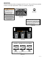
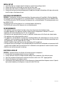
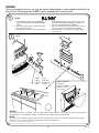
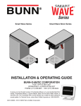
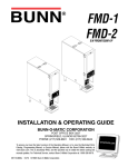
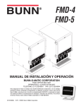
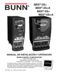
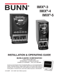
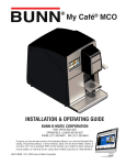
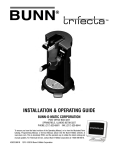
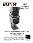
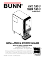
FMD DBC-3
FMDA DBC-3
SN FMD0013000-UP
INSTALLATION & OPERATING GUIDE
BUNN-O-MATIC CORPORATION
POST OFFICE BOX 3227
SPRINGFIELD, ILLINOIS 62708-3227
PHONE: (217) 529-6601 FAX: (217) 529-6644
To ensure you have the latest revision of the Operating Manual, or to view the Illustrated Parts
Catalog, Programming Manual, or Service Manual, please visit the Bunn-O-Matic website, at
www.bunn.com. This is absolutely FREE, and the quickest way to obtain the latest catalog and
manual updates. For Technical Service, contact Bunn-O-Matic Corporation at 1-800-286-6070.
29215.0000L 01/13 © 1998 Bunn-O-Matic Corporation
BUNN-O-MATIC COMMERCIAL PRODUCT WARRANTY
Bunn-O-Matic Corp. (“BUNN”) warrants equipment manufactured by it as follows:
1) Airpots, thermal carafes, decanters, GPR servers, iced tea/coffee dispensers, MCP/MCA pod brewers thermal servers
and Thermofresh servers (mechanical and digital)- 1 year parts and 1 year labor.
2) All other equipment - 2 years parts and 1 year labor plus added warranties as specified below:
a) Electronic circuit and/or control boards - parts and labor for 3 years.
b) Compressors on refrigeration equipment - 5 years parts and 1 year labor.
c) Grinding burrs on coffee grinding equipment to grind coffee to meet original factory screen sieve analysis - parts
and labor for 4 years or 40,000 pounds of coffee, whichever comes first.
These warranty periods run from the date of installation BUNN warrants that the equipment manufactured by it will be
commercially free of defects in material and workmanship existing at the time of manufacture and appearing within the
applicable warranty period. This warranty does not apply to any equipment, component or part that was not manufactured
by BUNN or that, in BUNN’s judgment, has been affected by misuse, neglect, alteration, improper installation or operation,
improper maintenance or repair, non periodic cleaning and descaling, equipment failures related to poor water quality,
damage or casualty. In addition, the warranty does not apply to replacement of items subject to normal use including but
not limited to user replaceable parts such as seals and gaskets. This warranty is conditioned on the Buyer 1) giving BUNN
prompt notice of any claim to be made under this warranty by telephone at (217) 529-6601 or by writing to Post Office
Box 3227, Springfield, Illinois 62708-3227; 2) if requested by BUNN, shipping the defective equipment prepaid to an
authorized BUNN service location; and 3) receiving prior authorization from BUNN that the defective equipment is under
warranty.
THE FOREGOING WARRANTY IS EXCLUSIVE AND IS IN LIEU OF ANY OTHER WARRANTY, WRITTEN OR ORAL, EXPRESS OR IMPLIED, INCLUDING, BUT NOT LIMITED TO, ANY IMPLIED WARRANTY OF EITHER MERCHANTABILITY
OR FITNESS FOR A PARTICULAR PURPOSE. The agents, dealers or employees of BUNN are not authorized to make
modifications to this warranty or to make additional warranties that are binding on BUNN. Accordingly, statements by such
individuals, whether oral or written, do not constitute warranties and should not be relied upon.
If BUNN determines in its sole discretion that the equipment does not conform to the warranty, BUNN, at its exclusive option while the equipment is under warranty, shall either 1) provide at no charge replacement parts and/or labor (during the
applicable parts and labor warranty periods specified above) to repair the defective components, provided that this repair
is done by a BUNN Authorized Service Representative; or 2) shall replace the equipment or refund the purchase price for
the equipment.
THE BUYER’S REMEDY AGAINST BUNN FOR THE BREACH OF ANY OBLIGATION ARISING OUT OF THE SALE OF THIS
EQUIPMENT, WHETHER DERIVED FROM WARRANTY OR OTHERWISE, SHALL BE LIMITED, AT BUNN’S SOLE OPTION
AS SPECIFIED HEREIN, TO REPAIR, REPLACEMENT OR REFUND.
In no event shall BUNN be liable for any other damage or loss, including, but not limited to, lost profits, lost sales, loss of
use of equipment, claims of Buyer’s customers, cost of capital, cost of down time, cost of substitute equipment, facilities
or services, or any other special, incidental or consequential damages.
392, A Partner You Can Count On, AutoPOD, AXIOM, BrewLOGIC, BrewMETER, Brew Better Not Bitter, BrewWISE, BrewWIZARD, BUNN Espress, BUNN Family Gourmet, BUNN Gourmet, BUNN Pour-O-Matic, BUNN, BUNN with the stylized
red line, BUNNlink, Bunn-OMatic, Bunn-O-Matic, BUNNserve, BUNNSERVE with the stylized wrench design, Cool Froth,
DBC, Dr. Brew stylized Dr. design, Dual, Easy Pour, EasyClear, EasyGard, FlavorGard, Gourmet Ice, Gourmet Juice, High
Intensity, iMIX, Infusion Series, Intellisteam, My Café, Phase Brew, PowerLogic, Quality Beverage Equipment Worldwide,
Respect Earth, Respect Earth with the stylized leaf and coffee cherry design, Safety-Fresh, savemycoffee.com, Scale-Pro,
Silver Series, Single, Smart Funnel, Smart Hopper, SmartWAVE, Soft Heat, SplashGard, The Mark of Quality in Beverage
Equipment Worldwide, ThermoFresh, Titan, trifecta, Velocity Brew, Air Brew, Air Infusion, Beverage Bar Creator, Beverage Profit Calculator, Brew better, not bitter., BUNNSource, Coffee At Its Best, Cyclonic Heating System, Daypart, Digital
Brewer Control, Element, Nothing Brews Like a BUNN, Pouring Profits, Signature Series, Tea At Its Best, The Horizontal
Red Line, Ultra are either trademarks or registered trademarks of Bunn-O-Matic Corporation. The commercial trifecta®
brewer housing configuration is a trademark of Bunn-O-Matic Corporation.
2
29215 080112
USER NOTICES
Carefully read and follow all notices on the equipment and in this manual. They were written for your protection.
All notices are to be kept in good condition. Replace any unreadable or damaged labels.
! WARNING
Fill water tank before turning - on thermostat or connecting appliance
to power source.
Use only on a properly protected
circuit capable of the rated load.
Electrically ground the chassis.
Follow national/local electrical codes.
Do not use near combustibles.
00824.0002
FAILURE TO COMPLY RISKS EQUIPMENT
DAMAGE, FIRE, OR SHOCK HAZARD
READ THE ENTIRE OPERATING MANUAL
BEFORE BUYING OR USING THIS PRODUCT
37881.0000
THIS APPLIANCE IS HEATED WHENEVER
CONNECTED TO A POWER SOURCE
00831.0000F 3/98 ©1998 BUNN-O-MATIC CORPORATION
As directed in the International Plumbing Code of the
International Code Council and the Food Code
Manual of the Food and Drug Administration (FDA),
this equipment must be installed with adequate
backflow prevention to comply with federal, state
and local codes. For models installed outside the
U.S.A., you must comply with the applicable Plumbing /Sanitation Code for your area.
00831.0000
00656.0001
Artwork for P/N: 00656.0001
Artwork Rev: A
Drawn: REF
Date: 04/22/10
29216.0000
CONTROL THERMOSTAT ADJUSTMENT
HI
HI
190 F
BUNN
HI
200 F
NN
F
OF
NN
OFF
BU
OFF
BU
180 F
APPROXIMATE THERMOSTAT TEMPERATURE SETTINGS
28368.0004A 08/08 © 2008 BUNN-O-MATIC CORPORATION
28368.0004
3
29215 051111
INITIAL SET-UP
1.
2.
3.
4.
Locate the drip tray assembly above the dispenser nested in the packing material.
Remove the drip tray and the drip tray cover and set them aside.
Remove the water strainer assembly from the drip tray and set it aside.
Remove the four legs from the packaging material, apply non-skid pads to the bottom of the legs and securely
install the legs in the dispenser base.
ELECTRICAL REQUIREMENTS
CAUTION - The dispenser must be disconnected from the power source until specified in Electrical Hook-Up.
The 120 volt version of this dispenser has an attached cordset. The mating connector must be a NEMA 5-15R.
The 120/208 volt and the 120/240 version of this dispenser has an attached cordset. The mating connector must
be a NEMA 14-20R.
The 240 volt version of this dispenser has an attached cordset without plug.
The 220-240 volt version of this dispenser has an attached cordset.
CE REQUIREMENTS
• This appliance must be installed in locations where it can be overseen by trained personnel.
• For proper operation, this appliance must be installed where the temperature is between 5°C to 35°C.
• Appliance shall not be tilted more than 10° for safe operation.
• An electrician must provide electrical service as specified in conformance with all local and national codes.
• This appliance must not be cleaned by water jet.
• This appliance is not intended for use by persons (including children) with reduced physical, sensory or mental
capabilities, or lack of experience and knowledge, unless they have been given instructions concerning use of
this appliance by a person responsible for its safety.
• Children should be supervised to ensure they do not play with the appliance.
• If the power cord is ever damaged, it must be replaced by the manufacturer or authorized service personnel with
a special cord available from the manufacturer or its authorized service personnel in order to avoid a hazard.
• Machine must not be immersed for cleaning.
Electrical Hook-Up
CAUTION - Improper electrical installation will damage electronic components.
1.
2.
3.
4.
5.
An electrician must provide electrical service as specified.
Using a voltmeter, check the voltage and color coding of each conductor at the electrical source.
Open the front door of the dispenser and place the heater switch in the “OFF” (upper) position.
Connect the dispenser to the power source.
If plumbing is to be hooked up later be sure the dispenser is disconnected from the power source. If plumbing has been hooked up, the dispenser is ready for Initial Fill & Heat.
4
29215 011510
PLUMBING REQUIREMENTS
This dispenser must be connected to a cold water system with operating pressure between 20 and 90 psi (138
and 620 kPa) from a 1/2˝ or larger supply line. A shut-off valve should be installed in the line before the brewer.
Install a regulator in the line when pressure is greater than 90 psi (620 kPa) to reduce it to 50 psi (345 kPa). The
water inlet fitting is .75-11.5 NH (HOSE THREAD). For convenience an elbow adaptor is provided to convert to
a 1/4˝ flare fitting. Bunn-O-Matic does not recommend the use of a reverse-osmosis or deionized water supply
to this equipment. REQUIRED: 1.0 gpm (3.78 lpm) flow rate from water supply line.
NOTE - At least 18 inches of an FDA approved flexible beverage tubing, such as reinforced braided polyethylene
or silicone, before the dispenser will facilitate movement to clean the countertop. Bunn-O-Matic does not recommend the use of a saddle valve to install the dispenser. The size and shape of the hole made in the supply line
by this type of device may restrict water flow.
As directed in the International Plumbing Code of the International Code Council and the Food Code
Manual of the Food and Drug Administration (FDA), this equipment must be installed with adequate
backflow prevention to comply with federal, state and local codes. For models installed outside the
U.S.A., you must comply with the applicable Plumbing /Sanitation Code for your area.
PLUMBING HOOK-UP (Early Models)
1. Securely attach the short piece of tubing on the water strainer assembly to the inlet fitting on the bottom of
the dispenser.
2. Flush the water line and securely attach it to the flare fitting on the water strainer assembly.
3. Turn-on the water supply.
PLUMBING HOOK-UP (Late Models)
1. Flush the water line and securely attach it to the elbow fitting on the bottom of the dispenser.
2. Turn-on the water supply.
NOTE - Water pipe connections and fixtures directly connected to a potable water supply shall be sized, installed
and maintained in accordance with federal, state and local codes.
INITIAL fill & heat
CAUTION - The dispenser must be disconnected from the power source throughout the initial fill & heat, except
when specified in the instructions.
1. Turn on the water supply and connect the dispenser to the power source.
2. Water will automatically flow into the tank to the proper level and then shut-off. This will take less than five
minutes.
3. When the tank is full of water, open the front door and place the heater switch in the “ON” (lower) position.
A tank full of cold water will take approximately forty minutes for the water to heat on 120 volt versions, and
twenty minutes on 120/240, and 220-240 volt versions.
During this waiting period, complete these dispenser set-up steps:
a. Place a set of keyholes in the splash panel over the screws beneath the hopper access door and push down
gently.
b. Place the drip tray onto the supports on the splash panel. Hook the tabs on the rear of the drip tray through
the holes in the splash panel. Set the drip tray cover in place.
c. Fill the hopper(s) with the dry product to be dispensed.
PRESET TANK TEMPERATURE
Tank temperatures have been preset at the factory to 180°F (82°C). Bunn recommends that to provide the best
quality beverage, the installer adjust the tank temperature to the powder product manufacturer’s recommended
temperature for the hot powder product being used.
5
29215 010413
LIQUID LEVEL CONTROL
The system automatically maintains the hot water tank’s level by energizing the refill solenoid when the water
level drops below the liquid level probe. If the system has not successfully refilled in 15 minutes, a refill error
occurs.
When a refill error occurs, the refill solenoid is de-energized and the 3 position L.E.D.’s will flash sequentially;
left...center...right...left...center...right...etc.
Once the cause of the refill error has been investigated (see the troubleshooting guide) and cured, the system
can be reset by either disconnecting (for at least 5 seconds) and then reconnecting the power to the machine,
or by entering one of the program modes (see Programming Modes.)
RINSE TIMER
The dispenser is shipped from the factory with the rinse timer disabled. To enable the rinse timer, remove power
from the dispenser, remove the lower access panel, and remove the jumper from J4 of the control board. For
dispensers with hot water dispense, remove power from the dispenser, remove the lower access panel, and disconnect the green wires coming from J4 of the control board from each other. Replace the lower access panel,
and return power to the dispenser.
When enabled, the rinse timer automatically keeps track of the time since the dispenser was last run through
a rinse sequence. If the dispenser detects that a rinse sequence has not been run for 8 hours, all three position
L.E.D.’s will flash continually. If, after an additional 4 hours (12 hours total), a rinse cycle has still not been run,
all three position L.E.D.’s will light continuously, and the hopper drives will be disabled until a rinse sequence
has been run.
RUNNING A RINSE SEQUENCE
1. Place the Rinse/Run switch in the “rinse” position .
2. Sequentially or simultaneously at each of the three positions, press any of the three dispense switches. The
dispenser will run for 10 seconds with the hopper(s) disabled.
3. As each position is rinsed, the corresponding L.E.D. will extinguish, indicating that the rinse cycle took
place.
4. After all three position L.E.D.’s have extinguished, the rinse timer is reset.
5. Return the Rinse/Run switch to the “run” position.
DISPENSER USE
1. Simply place a cup on the drip tray beneath the desired dispensing tip.
2. a) Momentarily press the appropriate dispense switch to froth and dispense the beverage. The dispenser will
automatically dispense the beverage for the programmed dispense time at the programmed hopper dispense
rate. The dispenser is factory preset to produce the approximate dispense sizes as follows:
Small (8 seconds): approximately 8 fluid ounces of beverage.
Medium (12 seconds): approximately 12 fluid ounces of beverage.
Large (16 seconds): approximately 16 fluid ounces of beverage.
To stop a timed dispense, press the stop switch or any of the switches on the position that is running.
Note - The mixing chamber must drain at the end of each dispense.
The dispense times can be individually programmed by following the procedures described in Programming
Modes.
b) Hot Water - Push and hold the hot water switch until the water reaches the desired level, then release.
6
29215 011510
HOPPER DISPENSE RATE OF PRODUCT
The hopper dispense rates are preset at the factory. With 22 tooth gear and auger wire, the preset dispense
rate is approximately 3 to 5 grams per second. With 30 tooth gear and auger wire, the preset dispense rate is
approximately 5 to 7 grams per second. The hopper dispense rates can be individually programmed to a range
of dispense rates from approximately 1.5 to 12 grams per second by following the procedures described in
Programming Modes.
PROGRAMMING MODES
1. Enter / Exit:
a. To enter the program mode, press any two dispense size switches, on the position to be programmed, at the
same time. The L.E.D. will flash indicating the program mode.
b. To exit the program mode, press a switch on any position other than the one being programmed.
Note: The stop switch will not cause exit of program mode since it is used for some programming operations.
If in the program mode for more than 25 seconds and no switches have been pressed, the program mode is
automatically exited.
2. Dispense Run Time:
a. Enter the program mode on the position you want to program (see step 1.a.)
b. Place the “Rinse/Run” switch in the “Run” position and press and hold the cup size to be programmed.
c. When the desired amount is reached, release the switch, the time is recorded in memory.
To set the time to non-timed dispense, just momentarily press the position switch. This actually sets in a very
short timed dispense.
d. Repeat for remaining cup sizes if desired.
e. Exit the programming mode (see step 1.b.)
3. Increasing / Decreasing the Hopper Dispense Rate:
a. Enter the program mode on the position you want to program (see step 1.a.)
b. Place the Rinse/Run switch in the “Rinse” position.
c. Press and hold down on the stop switch and press the small switch to decrease the dispense rate or press
the large switch to increase the dispense rate. Each time the button is pressed, the dispense rate will increase/
decrease by approximately 21/2 %. Each time the small or large switch is pressed, the L.E.D. on that position
will flash on and off to indicate the switch was recognized. When the maximum or minimum level is reached
all 3 position L.E.D.’s will flash rapidly.
d. To return the dispense rate to the factory preset, press and hold down stop switch and press the medium
switch. When the medium switch is pressed, the L.E.D. on that position will flash on and off to indicate the
switch was recognized.
e. Return the Rinse/Run switch to the “Run” position.
f. Exit the programming mode (see step 1.b.)
4. Making Common Timed Dispenses: Once a position has been programmed to the proper dispense times,
you can make all 3 positions the same, as follows:
a. Place the Rinse/Run switch in the “Run” position.
b. Enter the program mode on the position you want all others to be like (see step 1.a.)
c. Press and hold the Stop switch for 10 seconds.
d. After the 10 second period, all 3 position L.E.D.’s will come on solid indicating the task is complete. The
program mode is exited when the Stop switch is released.
7
29215 011510
5. Running Hopper Throw Test: The hopper throw can be checked by automatically running the hopper motor
as follows:
a. Remove the steam collector and mixing chamber from under the hopper to be checked.
b. Position a small cup under the hopper outlet.
c. Enter the program mode on the position you want to check (see step 1.a.)
d. Place the Rinse/Run switch in the “Run” position.
e. Press and hold the stop switch down and press the small, medium, or large switch. The hopper will run for
the programmed timed dispense period at the programmed dispense rate.
f. Remove the cup and weigh the dispensed product.
g. Exit the programming mode (see step 1.b.)
h. Replace the mixing chamber and steam collector.
6. Making Common Dispense Rates: Once a position has been programmed to the proper hopper dispense rate,
you can make all 3 positions approximately the same, as follows:
a. Place the Rinse/Run switch in the “Rinse” position.
b. Enter the program mode on the position you want all others to be like (see step 1.a.)
c. Press and hold the Stop switch for 10 seconds.
d. After the 10 second period, all 3 position L.E.D.’s will come on solid indicating the task is complete. The
program mode is exited when the Stop switch is released.
e. Return the Rinse/Run switch to the “Run” position.
7. Password: The password is to be used to prevent unauthorized entering of the program modes. The password
is preset at the factory to 0 (no password.)
a. To enter the password programming, press and hold any two dispense size switches on any one of the positions for 10 seconds. All 3 position L.E.D.’s will begin flashing indicating that the dispenser is ready to accept
a new password.
b. When the switches are released the 3 L.E.D.’s will stop flashing. At this time press the Stop switch the number of times that is the password (For example: If you press the Stop switch 5 times, you will then have to
press the Stop switch 5 times before you will be able to enter the program mode the next time.)
c. 5 seconds after the Stop switch is pressed for the last time, the password is recorded in memory. As a
verification of the password, when the 5 seconds is up, the 3 L.E.D.’s will flash the password. (For example:
If the password is 5, when the exit of the password occurs, the L.E.D. will flash 5 times.)
d. Thereafter, the Stop switch needs to be pressed the password number of times before the program mode
can be entered.
NOTE: After 5 seconds of pressing the Stop switch for the final time, the password counter is reset to 0. So if
the password is mis-entered, wait 5 seconds before trying again.
e. To reset the password to 0 (no password,) enter the old password, then press and hold any two dispense
size switches on any one of the positions for 10 seconds. All 3 position L.E.D.’s will begin flashing indicating
that the dispenser is ready to accept a new password. Then just wait 5 seconds without pressing the Stop
switch.
NOTE: There will be no indication when the 5 seconds are up and the password is reset to 0.
8
29215 011510
RE-INITIALIZE TO FACTORY DEFAULTS
This resets all dispense time settings and hopper throw rates to the factory defaults, and resets the password
to 0 (no password.)
1. Disconnect the dispenser from the power source.
2. Place the Rinse/Run switch in the “Run” position.
3. Press and hold the left small, center small, and the Stop switches at the same time.
4. While holding the switches, connect the dispenser to the power source (this is intended to be difficult.) The
switches must be held for about 5 seconds. When the task is completed, the left, center and right L.E.D.’s
flash until the switches are released.
5. Wait an additional 10 seconds before operating the dispenser.
cold beverage set-up (Optional)
Cold beverages may be dispensed from the left dispense position. Simply place the HOT/COLD switch near the
left whipper chamber in the “COLD” (upper) position.
Adjustments
The hot or cold beverage solenoids are preset to dispense approximately 9/10 ounce per second. This amount
can be adjusted:
1. Disconnect the dispenser from the power source.
2. Remove the small left side access panel.
3. Rotate the control at the base of the desired solenoid(s) clockwise to decrease or counterclockwise to increase
the amount of water.
4. For cold beverage adjustment remove the 1-1/2” plug on the lower left side of the dispenser and rotate the
needle valve clockwise to decrease or counterclockwise to increase the amount of cold water.
DRAINING THE hot water tank
CAUTION - The dispenser must be disconnected from the power source throughout these steps
1. Disconnect the dispenser from the power source.
2. Open front door and place tank heater switch in the “OFF” (upper) position.
3. Shut off and disconnect the incoming water supply.
4. Remove the top panel.
5. Gently remove one of the grommets from the tank lid.
6. Insert a tube to the bottom of the tank and syphon ALL of the water out.
NOTE - The dispenser must be refilled using the INITIAL FILL & HEAT steps before reconnecting to the power
source.
PREVENTIVE MAINTENANCE
Bunn-O-Matic® Corporation recommends that preventive maintenance be performed at regular intervals. Maintenance
should be performed by a qualified service technician. For Technical Service, contact Bunn-O-Matic® Corporation at
1-800-286-6070.
NOTE: Replacement parts or service caused by failure to perform required maintenance is not covered by warranty.
Cycle
Item
(months)
6
Mixing Chamber Kit
Part Number
32906.0000
6
Whipper Motor Seal Kit
29128.0000
3 or as
needed
Whipper Shaft Seal Kit
26356.1000
9
29215 011510
CLEANING
The use of a damp cloth rinsed in any mild, non-abrasive, liquid detergent is recommended for cleaning all surfaces on Bunn-O-Matic equipment. Do NOT clean this equipment with a water jet device.
1 x 24h
1. Rinse out Whipper Chambers by placing RINSE/RUN
switch in the "RINSE" position and activating DISPENSE
switches.
2. Turn elbow up, remove Hoppers, refill with product and
replace hoppers into dispenser.
3. Empty Drip Tray and wash in a solution of dish detergent.
7
1. Para limpiar las camaras de mezcla, coloque el interruptor en la
posicón ENJUAGUE/MARCHA (”RINSE/RUN”) y pulse el boton
para espumar y distribuir la bebida (”DISPENSE”).
2. Gire el codo hacia arriba, remueva las tolvas, llene las tolvas con
producto y coloque las tolvas nuevamente en la maquina.
3. Vacie la bandeja de goteo y limpiela con un detergente liquido
suave no abrasivo.
1 x 7d
9
1
6
2
8
7
5
3
4
a. Wash
b. Rinse
c. Sanitize
d. Dry
a
b
a. Lave
b. Enjuague
c. Desinfecte
d. Seque
Replace Light Bulbs
as required.
Cambie los bombillos
quemados cuando
sea necesario.
c
NOTICE
The cleaning instructions noted above are for non-dairy sugar based food products. When dispensing any other food product,
the cleaning cycle for the whipping chamber assembly and ejector elbow must be performed daily.
NOTA:
Las instrucciones de limpieza descritas anteriormente excluyen productos lacteos azucarados. La limpieza de las camaras
de mezcla y de los codos de salida de cada tolva deberá realizarse diariamente.
37254.0000A 07/04 © 2004 BUNN-O-MATIC CORPORATION
10
29215 060509