1
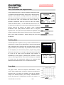
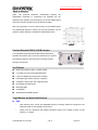
ISO‐9001 CERTIFIED MANUFACTURER LCR-8110G/8105G, 10MHz / 5 MHz Precision LCR Meter New Product Announcement Two high frequency LCR Meters, LCR-8110G and LCR-8105G have come joining LCR-8000G series family as the new members. Following the evolution of telecom technology, the impedance measurement for components and modules has come to a high frequency era. LCR-8110G, featuring 10MHz test frequency, and LCR-8105G, featuring 5MHz, meet the requirements of impedance measurement under a high frequency environment. The component characteristic verification using a test frequency, which simulates the real circuit operation, ensures the best test result and significantly reduces the trail-and-error time. LCR-8000G Series LCR meter provides accuracy, versatility and high resolution for a wide range of component measurements, even including DC resistance measurement and Voltage/Current monitoring. The Multi-Step function allows on-screen programming of customized measurement sequence with Pass/Fail indication. Each program includes 30 test steps and each test step can be set with selected parameters and test limits. Under Multi-Step operation, a tedious work routine can be done step by step automatically just at a press of a button. With Graph Mode, LCR-8110G and LCR-8105G display the component impedance response either over a wide range of test frequency sweep or over a wide range of test voltage sweep in a graph chart. This gives an analysis result of either impedance vs. frequency or impedance vs. applied voltage all at a glance. GPIB and RS-232C interfaces are available as standard for instrument control and test result display on the PC. The rich features of LCR-8000G series easily make your measurement tasks done at a very competitive price. Wide Frequency Range with Friendly Intuitive User Interface The LCR-8000G series is designed to perform precision impedance measurements over a wide frequency range of 20 Hz to 1 MHz for LCR-8101G, 20 Hz to 5 MHz for LCR-8105G and 20Hz to 10 MHz for LCR-8110G. The instrument is capable of measuring 11 different parameters with 0.1% basic accuracy, which meets the precision measurement requirements of components and modules used in the RF circuits. The large LCD display with single-layer operation menu of LCR-8000G series provides users with ultimate convenience to plug and play without much learning time. LCR8100G NPI Announcement 1 OF 6 1/28/2010 ISO‐9001 CERTIFIED MANUFACTURER Pass / Fail Function with Judgment Alarm In the Pass/Fail test mode, the primary parameter measurement result is compared with user-defined limits, and the pass or fail result is then displayed. Three methods, including absolute limit, percentage and delta limit, are available for Hi (high) and Lo (low) limit setting based on the nominal test value. The Pass/Fail test checks whether the parameter measurement result sits within the limits, then display *7 MEASUREMENT MODE 0.01234 mF – 0.2179 D LO CLXBZY QDRG Parallel Hi +1.00% Hide Scale Lo –1.00% Abs % 50mVac 1.5000kHz Vm:549.8mV Range Auto Save Nom Im:724.9pA Speed Med 53.388fF “PASS” for within the limits, or “LO” for lower than the low limit, or “HI” for higher than the high limit. A scale and bar for displaying measurement result is shown at the center of the screen to give a graphical identification, which greatly reduces operator’s load in a long time inspection work. This scale and bar also facilitate the adjustment of the variable components. Either Pass or Fail result can be set with a buzzer alarm, which makes component or material sorting easy with sound identification. Multi Step Mode The Multi-Step mode is capable of running a series of measurements of a component at a number of user-defined steps in sequence automatically. Total 64 programs can be saved into the non-volatile memory, and each program contains up to 30 test steps. The parameter and Hi/Lo limits can be set respectively for each test step. After a program being properly edited, the instrument can run through all the measurement steps either MULTI STEP MODE – Set PROGRAM: NEW 01 02 03 Step Ls Ls Func Ls Freq 1.0000k 10.000k 100.00k Volt 1.00 V 1.00 V 1.00 V Bias FAST FAST FAST Spd Hi 2.0000mH 2.0000mH 2.0000mH 0.1000mH 0.1000mH 0.1000mH Lo 0 mS 0 mS 0 mS Dly Prog Copy Delete Save File RUN at a press of the button under the Manual Trigger selection, or automatically run the program by detecting the connection of a DUT under the Auto Trigger selection. When all the test steps are completed, the screen shows the measurement reading of the parameter being MULTI STEP MODE – Run PROGRAM: NEW Result Volt Freq 1 1.0000k 1.00 Ls 0.0936mH 2 10.000k 1.00 Ls 1.8708mH 3 100.00k 1.00 Ls 2.5852mH Start LO PASS HI selected for each step with Pass, HI, or LO measurement result. FAIL SET Graph Mode The graph function shows the component characteristics in visual manner. Either voltage sweep or frequency sweep can be selected for horizontal scale. Just select the parameter, and set the start/stop voltage or the start/stop frequency of the sweep, LCR-8000G will run through the sequence of measurements and show the results on a LCR8100G NPI Announcement 2 OF 6 1/28/2010 ISO‐9001 CERTIFIED MANUFACTURER graph. This graphical parameter measurement performs the characteristic verification of components and materials over the response to the changes in AC test frequency or AC test voltage without the need of complex programming of an external controller. When the graph gets out of the vertical range, the LCR-8000G series can automatically adjust the scale to get full test information. On the graph the marker operation is available for detailed observation. Practical Standard RS-232 & GPIB Interface The LCR-8000G series features GPIB & RS232 interfaces as standard. Each allows user to control the instrument or to capture the measuring data from the instrument for a further analysis through an external PC. Key Features Wide Test Frequency 20Hz ~ 10 MHz / 5 MHz 0.1% Basic Accuracy with 6 Digits Resolution DC Resistance Measurement Large LCD Display with Intuitive User Interface Full Measuring Functions with DUT V/I Monitor PASS/FAIL Test Function with Judgment Alarm Multi Step Mode Graph Mode Standard RS-232/GPIB Interface Target Markets and Associated Features ̶ R&D High frequency drive source with adjustable frequency continuity allows the component to be measured under the real operation environment. ̶ Graph mode for component and material verification based on the sweep of either AC test frequency or voltage. LCR8100G NPI Announcement 3 OF 6 1/28/2010 ISO‐9001 CERTIFIED MANUFACTURER Quality Assurance Verification ̶ Wide frequency range to cover most of the characteristic measurement items for a broad variety of components. ̶ Pass/ Fail Test function with buzzer alarm makes the heavy duty of component or material measurement job easy ̶ Multi-step function, with each program containing 30 test steps, performs the routine measurements in sequence just at a push of the run button Education Lab and Training Institution ̶ Wide frequency range to cover most of the characteristic measurement items for a broad variety of components. ̶ High Resolution & Accuracy provide precision measurement results, which helps verify component characteristics. ̶ Graph mode for verification of component and material response to the changes of either AC test frequency or voltage. Key Dates for Product Announcement 1. Order queue open (December 21th , 2009) 2. Distributor Announcement (December 21th ,2009)) 3. Global Market Announcement (Mid-December, 2009) 4. Demo Units Shipped to Distributors (End of December, 2009) 5. Mass quantity order fulfillment (End of December, 2009) Service Policy 1. One (1) year warranty 2. Service Support The service instructions in the Service Manual will help distributors repair defective units promptly. Should the board replacement is necessary to fix the defective unit, the board swapping service support is provided by GW Instek to facilitate the repair jobs done at the distributor’s site. 3. GW Instek continuingly provides the after-sales support through its website. The most up-to-date version of service manual and Marcom material of LCR-8000G series will be posted on the distributor zone of GW Instek Website at http://www.gwinstek.com. LCR8100G NPI Announcement 4 OF 6 1/28/2010 ISO‐9001 CERTIFIED MANUFACTURER Specifications Wide Test Frequency 20Hz ~ 10 MHz / 5 MHz 0.1% Basic Accuracy with 6 Digits Resolution Large LCD Display with Intuitive User Interface Full Measuring Functions with DUT V/I Monitor PASS/FAIL Test Function with Judgment Alarm DC Resistance Measurement Multi Step Mode Graph Mode Test Frequency Standard RS-232/GPIB Interface 20Hz ~ 10 MHz / 5MHz, 5 Digits, 0.005% Input Impedance Basic Accuracy 100Ω ±0.1% (R, Z, X, G, Y, B, L, C) Test Speed DC AC (>2kHz) MAX: 30mS MAX: 75mS FAST: 60mS FAST: 150mS MEDIUM: 120mS MEDIUM: 450mS SLOW: 900mS SLOW: 600mS ≦3MHz:10mV~2Vrms, 1mV or 10mV/Step, 2%±5mV >3MHz:10mV~1Vrms, 1mV or 10mV/Step, 2%±5mV Test Signal Levels Short Circuit Current Max. 20mA Measurement Ranges Series/ Parallel Equivalent Circuit 0.1mΩ ~ 100MΩ R, Z, X 10nS ~ 1000S G, Y, B 0.1nH ~ 100kH L 0.01pF ~ 1F C 0.00001 ~ 9.9999 D 0.1 ~ 9999.9 Q -180∘~ +180∘ θ 0.1mΩ ~ 100MΩ Rdc Impedance (Z), Phase Angle (θ), Inductance (L), Capacitance (C), AC Resistance (Rac), Quality Factor (Q), Dissipation Factor (D), Admittance (Y), Conductance (G), Reactance (X), Susceptance (B), DC Resistance (Rdc) C + R, C + D, C + Q, L + R, L + Q, L + D Series Equivalent Circuit Only X + R, X + D, X + Q Parallel Equivalent Circuit Only C + G, B + G, B + D, B + Q, B + R, L + G Polar Form Z + Phase Angle, Y + Phase Angle LCD Display 320 x 240 DOT-MATRIX Interface RS-232, GPIB Power Source AC 115V±10% /230V±10% (Selectable), 50/60Hz Accessories User manual x1, Power cord, Test lead LCR-12 x 1 Dimensions & Weight 330(W) x 170(H) x 340(D)mm, Approx. 5kg Measurement Parameters LCR8100G NPI Announcement 5 OF 6 1/28/2010 ISO‐9001 CERTIFIED MANUFACTURER Ordering Information LCR-8110G 10 MHz Precision LCR Meter LCR-8105G 5 MHz Precision LCR Meter Standard Accessories User Manual x 1 Power Cord x 1 Test Lead LCR-12 x 1 Optional Accessories Accessory Model Brief Description LCRLCR8101G 8105G LCR-05 Test Fixture for axial & radial leaded components ● △ LCR-06A Test Lead with Kelvin clip (4 wire type) ● △ LCR-07 Test Lead with Alligator clip (2 wire type) ● △ LCR-08 Test Fixture (Tweezers) for SMD/Chip components ● △ LCR-09 Test Fixture for SMD/Chip components ● ● LCR-13 Test Fixture for SMD/Chip components ● ● GTL-232 RS-232C Cable ● ● GRA-404 Rack Adapter Panel (19”, 4U) ● ● Note:”△” means the accessories work with a frequency limitation (under 1MHz) LCR-05 LCR-06A LCR-07 LCR-08 LCR-09 LCR8110G △ △ △ △ ● ● ● ● LCR-13 Should you have any questions on the LCR-8000G series announcement, please don’t hesitate to contact us Sincerely Yours; Marketing Department Instek America Corp. 3661 Walnut Avenue Chino, CA 91709. USA Email: [email protected] LCR8100G NPI Announcement 6 OF 6 1/28/2010