1
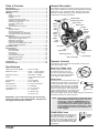
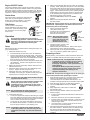
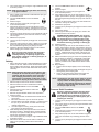
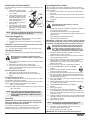
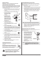
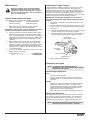
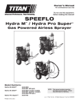
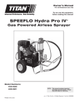
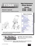
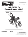
Owner’s Manual
For professional use only
Do not use this equipment
before reading this manual!
SPEEFLO
PowrLiner 800
Model Number
759-091
NOTE: This manual contains important
warnings and instructions. Please
read and retain for reference.
0611 •
© Titan Tool Inc. All Rights Reserved. Form No. 0528904C
Important Safety Information ·
Read all safety information before
operating the equipment. Save these instructions.
14. Plastic can cause static sparks. Never hang plastic to
enclose spray area. Do not use plastic drop cloths when
spraying flammable material.
15. Fire extinguisher equipment shall be present and working.
This symbol indicates a hazardous situation,
which, if not not avoided could result in death or
serious injury.
To reduce the risks of fire or explosion, electrical
shock, and the injury to persons, read and
understand all instructions included in this manual.
Be familiar with the controls and the proper usage
of the equipment.
WARNING – To reduce the risk of skin
injection:
HAZARD:
WARNING – To reduce the risk of fire or
explosion:
Injection injury – A high pressure fluid stream produced by
this equipment can pierce the skin and underlying tissues,
leading to a serious injury and possible amputation. See a
physician immediately. DO NOT TREAT AN INJECTION AS A
SIMPLE CUT.
1. Do not aim the gun at, or spray any person or animal.
2. Keep hands and other body parts away from the
discharge. For example, do not try to stop leaks with any
part of the body.
3. Always use the nozzle tip guard. Do not spray without the
nozzle tip guard in place.
4. Only use a nozzle tip specified by the manufacturer.
5. Use caution when cleaning and changing nozzle tips. In
the case where the nozzle tip clogs while spraying,
ALWAYS lock gun trigger, shut pump off, and release
all pressure before servicing, cleaning tip or guard, or
changing tip. Pressure will not be released by turning off
the motor. The PRIME/SPRAY valve or pressure bleed
valve must be turned to their appropriate positions to
relieve system pressure. Refer to PRESSURE RELIEF
PROCEDURE described in the pump manual.
6. Do not leave the unit energized or under pressure while
unattended. When the unit is not in use, turn off the
unit and relieve the pressure in accordance with the
manufacturer’s instructions.
7. High-pressure spray is able to inject toxins into the body
and cause serious bodily injury. In the event that injection
occurs, seek medical attention immediately.
8. Check hoses and parts for signs of damage, a leak can
inject material into the skin. Inspect hose before each use.
Replace any damaged hoses or parts.
9. This system is capable of producing 3300 PSI / 22.8
MPa. Only use replacement parts or accessories that
are specified by the manufacturer and that are rated a
minimum of 3300 PSI. This includes spray tips, nozzle
guards, guns, extensions, fittings, and hose.
10. Always engage the trigger lock when not spraying. Verify
the trigger lock is functioning properly.
11. Verify that all connections are secure before operating the
unit.
12. Know how to stop the unit and bleed pressure quickly. Be
thoroughly familiar with the controls. Pressure will not be
released by turning off the motor. The PRIME/SPRAY
valve or pressure bleed valve must be turned to their
appropriate positions to relieve system pressure. Refer
to PRESSURE RELIEF PROCEDURE described in the
pump manual.
13. Always remove the spray tip before flushing or cleaning
the system.
1. Do not spray flammable or combustible
materials near an open flame, pilot lights
or sources of ignition such as hot objects,
cigarettes, motors, electrical equipment and
electrical appliances. Avoid creating sparks
from connecting and disconnecting power cords.
2. For units intended for use with only water-based materials
— Do not spray or clean with flammable liquids. For use
with water-based liquids only.
3. For units intended for use with only water-based or mineral
spirit-type materials with a minimum flash point of 21ºC
(69.8ºF) — Do not spray or clean with liquids having a
flash point of less than 21ºC (69.8ºF). Flash point is the
temperature at which a fluid can produce enough vapor to
ignite.
4. Paint or solvent flowing through the equipment is able to
result in static electricity. Static electricity creates a risk of
fire or explosion in the presence of paint or solvent fumes.
All parts of the spray system, including the pump, hose
assembly, spray gun and objects in and around the spray
area shall be properly grounded to protect against static
discharge and sparks. Use only conductive or grounded
high-pressure airless paint sprayer hoses specified by the
manufacturer.
5. Verify that all containers and collection systems are
grounded to prevent static discharge.
6. Connect to a grounded outlet and use grounded extension
cords (electric models only). Do not use a 3 to 2 adapter.
7. Do not use a paint or solvent containing halogenated
hydrocarbons. Such as chlorine, bleach mildewcide,
methylene chloride and trichloroethane. They are not
compatible with aluminum. Contact the coating supplier
about compatibility of material with aluminum.
8. Keep spray area well ventilated. Keep a good supply of
fresh air moving through the area to keep the air within the
spray area free from accumulation of flammable vapors.
Keep pump assembly in well ventilated area. Do not spray
pump assembly.
9. Do not smoke in the spray area.
10. Do not operate light switches, engines, or similar spark
producing products in the spray area.
11. Keep area clean and free of paint or solvent containers,
rags, and other flammable materials.
12. Know the contents of the paint and solvents being
sprayed. Read all Material Safety Data Sheets (MSDS)
and container labels provided with the paints and solvents.
Follow the paint and solvent manufacture’s safety
instructions.
13. Place pump at least 25 feet (7.62 meters) from the
spray object in a well ventilated area (add more hose if
necessary). Flammable vapors are often heavier than
air. Floor area must be extremely well ventilated. The
pump contains arcing parts that emit sparks and can ignite
vapors.
2
© Titan Tool Inc. All rights reserved.
Important Safety Information ·
Read all safety information before
operating the equipment. Save these instructions.
Gasoline Engine Safety
WARNING – To reduce the risk of injury:
1. Always wear appropriate gloves, eye protection, clothing
and a respirator or mask when painting. Hazardous
vapors – Paints, solvents, insecticides, and other materials
can be harmful if inhaled or come in contact with body.
Vapors can cause severe nausea, fainting or poisoning.
2. Do not operate or spray near children. Keep children
away from equipment at all times.
3. Do not overreach or stand on an unstable support. Keep
effective footing and balance at all times.
4. Stay alert and watch what you are doing.
5. Do not operate the unit when fatigued or under the
influence of drugs or alcohol.
6. Do not kink or over-bend the hose. Airless hose can
develop leaks from wear, kinking and abuse. A leak can
inject material into the skin.
7. Do not expose the hose to temperatures or pressures in
excess of those specified by manufacturer.
8. Do not use the hose as a strength member to pull or lift the
equipment.
9. Use lowest possible pressure to flush equipment.
10. Follow all appropriate local, state and national codes
governing ventilation, fire prevention and operation.
11. The United States Government Safety Standards have
been adopted under the Occupational Safety and Health
Act (OSHA). These standards, particularly part 1910 of
the General Standards and part 1926 of the Construction
Standards should be consulted.
12. Before each use, check all hoses for cuts, leaks, abrasion
or bulging of cover. Check for damage or movement
of couplings. Immediately replace hose if any of those
conditions exist. Never repair a paint hose. Replace with
a conductive high-pressure hose.
13. Do not spray outdoors on windy days.
14. Always unplug cord from outlet before working on
equipment (electric models only).
1.
2.
3.
4.
5.
6.
7.
8.
9.
10.
11.
DO NOT use this equipment to spray water or acid.
important: Do not lift by cart handle when loading or
unloading.
© Titan Tool Inc. All rights reserved.
3
The engine exhaust from this unit contains
chemicals known to the State of California to cause
cancer, birth defects, or other reproductive harm.
Gas engines are designed to give safe and dependable
service if operated according to instructions. Read and
understand the engine Owner’s Manual before operating
the engine. Failure to do so could result in personal injury
or equipment damage.
To prevent fire hazards and to provide adequate
ventilation, keep the engine at least 1 meter (3 feet) away
from buildings and other equipment during operation. Do
not place flammable objects close to the engine.
Children and pets must be kept away from the area of
operation due to a possibility of burns from hot engine
components or injury from any equipment the engine may
be used to operate.
Know how to stop the engine quickly, and understand the
operation of all controls. Never permit anyone to operate
the engine without proper instructions.
Gasoline is extremely flammable and is explosive under
certain conditions.
Refuel in a well-ventilated area with the engine stopped.
Do not smoke or allow flames or sparks in the refueling
area or where gasoline is stored.
Do not overfill the fuel tank. After refueling, make sure the
tank cap is closed properly and securely.
Be careful not to spill fuel when refueling. Fuel vapor or
spilled fuel may ignite. If any fuel is spilled, make sure the
area is dry before starting the engine.
Never run the engine in an enclosed or confined area.
Exhaust contains poisonous carbon monoxide gas;
exposure may cause loss of consciousness and may lead
to death.
The muffler becomes very hot during operation and
remains hot for a while after stopping the engine. Be
careful not to touch the muffler while it is hot. To avoid
severe burns or fire hazards, let the engine cool before
transporting it or storing it indoors.
Never ship/transport unit with gasoline in the tank.
Table of Contents
General Description
Specifications............................................................................ 4
General Description.................................................................. 4
Operator Controls...................................................................... 4
Operation.................................................................................... 5
Setup.................................................................................... 5
Preparing to Paint................................................................ 5
Painting................................................................................ 6
Pressure Relief Procedure................................................... 6
Attaching the Tip Guard and Tip.......................................... 7
Clearing a Clogged Tip........................................................ 7
Changing a Spray Tip.......................................................... 7
Stenciling.............................................................................. 7
Operating the Front Caster.................................................. 7
Cleanup...................................................................................... 7
Special Cleanup................................................................... 8
Cleaning the Spray Tip......................................................... 8
Cleaning/Replacing the Gun Filter....................................... 8
Cleaning the Inlet Valve Assembly....................................... 8
Maintenance............................................................................... 9
General Repair and Service Notes...................................... 9
Adjusting the Trigger Tension.............................................. 9
Maintaining the Engine......................................................... 9
Safety Shut-Off Switch......................................................... 9
Replacing the PRIME/SPRAY Valve.................................. 10
Servicing the Fluid Section................................................. 11
Troubleshooting...................................................................... 12
Parts Listings........................................................................... 13
Main Assembly................................................................... 13
Drive Assembly.................................................................. 14
Spray Gun.......................................................................... 14
Cart Assembly.................................................................... 15
Fluid Section Assembly...................................................... 16
Gun Holder Assembly........................................................ 16
Labels................................................................................. 16
Electrical Schematic........................................................... 17
Accessories............................................................................. 17
Limited Warranty..................................................................... 20
This airless line striper is a precision power tool used to spray
many types of material for many types of applications including
parking lots, curbs, and athletic fields. Read and follow this
instruction manual carefully for proper operating instructions,
maintenance, and safety information.
Throttle Cable
Airless Spray Hose
Return Hose
Siphon Tube
Engine
Spray
Lever
Gun
Cable
Engine
ON/OFF
Switch
Outlet
Fitting
Caster
Radius
Knob
Oiler
Button
Fluid
Section
Gun Riser
Gun
Support Bar
PRIME/SPRAY
Knob
Airless Spray Gun
* Pail not included.
Operator Controls
The following section describes the operator controls on the
spray gun and line striper.
Specifications
Spray Gun Trigger Lock
Gallons per minute (GPM)������������� 0.33 (1.25 LPM)
Maximum tip size��������������������������� 0.019” — Traffic marking
0.023” — Field marking
Maximum pressure������������������������ 2500 PSI (17.2 MPa)
Power ����������������������������������������� 1.6 HP Robin-Subaru gas
engine
Fuel capacity��������������������������������� 0.17 US gallons
Weight ����������������������������������������� 65 lbs. (29.5 kg)
Inlet paint filter������������������������������� 10 mesh “rock catcher”
Hose connection���������������������������� 1/4” NPS(M)
Line width range���������������������������� 2”–12” (5–30 cm)
Dimensions������������������������������������ 41” L (104 cm)
21” W (53.3 cm)
32” H (81.3 cm)
Always engage the gun’s trigger
lock when the gun is not in use.
The gun is locked when the trigger
lock is at a 90º angle (perpendicular
to the trigger in either direction).
Spray Lever
The spray lever is a dual-function lever. It is
located on the cart handle. The spray lever
controls the throttle on the engine as well
as the trigger on the spray gun. The initial
pull of the spray lever engages the throttle
and revs up the engine. This engages the
Spray Lever
engine clutch with the pump and causes the
sprayer to build pressure. Fully pulling the
spray lever triggers the spray gun. While striping, the spray lever
should be fully pulled for proper operation.
IMPORTANT: Do not remove the spray gun from the gun
holder and attempt to use it independently. Doing this will
will engage the safety shut-off switch.
NOTE: The sprayer is equipped with an automatic safety
shut-off switch to prevent the sprayer from overpressurizing. When the PRIME/SPRAY knob is
in the SPRAY position, pulling and holding the
spray lever half way without triggering the spray
gun will engage the safety shut-off switch. Refer
to the Maintenance section if the safety shut-off
switch engages.
PRIME/SPRAY Knob
The PRIME/SPRAY knob directs fluid to
the spray hose when set to SPRAY or
the return tube when set to PRIME. It is
located on the side of the pump housing.
The arrows on the PRIME/SPRAY knob
show the rotation directions for PRIME
and SPRAY.
Tip Assembly
4
PRIME/
SPRAY
Knob
© Titan Tool Inc. All rights reserved.
Engine ON/OFF Switch
6. Make sure the throttle cable and gun cable are operating
properly. When pulling the spray lever on the cart handle,
the throttle cable should be fully moving the throttle lever
on the engine, and the gun cable should be pulling the gun
trigger. These cables are factory-set to operate properly.
If adjustment to the gun trigger tension is required, refer
to the “Adjusting the Trigger Tension” procedure in the
Maintenance section of this manual.
7. Turn the PRIME/SPRAY knob to the PRIME
position.
8. Make sure the engine ON/OFF switch is in
the OFF position.
The engine ON/OFF switch controls the operation of the gas
engine. Moving the engine ON/OFF switch to the ON position
allows the engine to be started using the starter rope. Moving
the engine ON/OFF switch to the OFF position shuts down the
engine if it is running and prevents it from starting if it is not.
Pusher Stem
The pusher stem is designed to keep the inlet
valve open by preventing the inlet ball from
sticking due to dried materials. It is located
on the side of the inlet valve assembly.
Oiler Button
The oiler button is designed to
provide lubrication to the fluid section
of the pump. After initial setup, press
the oiler button once for every eight
hours of use.
Operation
Pusher
Stem
IMPORTANT: Never operate unit for more than ten seconds
without fluid. Operating this unit without fluid will cause
unnecessary wear to the packings.
Oil Fill
Cap
9. Fill the oil reservoir with Piston
Lube (P/N 314-480, light
household oil may be substituted).
Press the oiler 2–5 times to
lubricate the fluid section.
Oil
Reservoir
Oiler
Button
NOTE:After initial setup, press
the oiler button once for
every eight hours of use.
Keep the oil reservoir
filled with Piston Lube.
This equipment produces a fluid stream at
extremely high pressure. Read and understand the
warnings in the Safety Precautions section at the
front of this manual before operating this
equipment.
Oil
Reservoir
Oiler
Button
10. Check the engine oil level. The
gasoline engine oil level is
determined by the manufacturer. Refer to the engine
manufacturer’s service manual (supplied).
11. Fill the gas tank on the engine with unleaded gasoline
only. Do not mix the gasoline with 2-cycle oil.
Setup
Perform the following procedure before starting the engine of a
gas-powered sprayer.
1. Attach the handle to the cart.
a. Insert the handle into the tube on the cart weldment.
b. Position the handle at the desired height. The handle
may be positioned at three different heights. Select the
appropriate two holes on the cart weldment and match
them up with the two holes on the handle.
c. Insert the supplied two screws through the handle and
cart weldment. Thread on the supplied lock nuts and
tighten securely.
2. Make sure that the siphon tube and the return hose are
attached and secure.
3. Attach the airless spray hose to the outlet fitting on the
sprayer. Tighten securely using a wrench
4. Attach the other end of the airless spray hose to the
inlet fitting on the spray gun. Tighten securely using two
wrenches (one on the gun and one on the hose).
Preparing to Paint
Before painting, it is important to make sure that the fluid in the
system is compatible with the paint that is going to be used.
NOTE: If this unit is new, it is shipped with test fluid
in the fluid section to prevent corrosion during
shipment and storage. This fluid must be
thoroughly cleaned out of the system before you
begin spraying.
Incompatible fluids and paint may cause the
valves to become stuck closed, which would
require disassembly and cleaning of the
sprayer’s fluid section.
IMPORTANT: Always keep the trigger lock on the spray gun
in the locked position while preparing the system.
1. Place the siphon tube into a container of the appropriate
solvent for the material being sprayed (refer to
recommendations of the material manufacturer). An
example of the appropriate solvent is water for latex paint.
2. Place the return hose into a metal waste container.
3. Turn the PRIME/SPRAY knob to the PRIME
position.
4. Fully depress the pusher stem to make sure
the inlet ball is free.
5. Move the engine ON/OFF switch to the ON position.
6. Start the engine:
a. Press the prime bulb underneath the air intake shroud
seven times.
b. Move the choke lever up to the full choke position.
c. Pull the starter rope rapidly and firmly. Continue to hold
the rope as you let it return. Pull and return the rope
until the engine starts.
d. Once the engine is running, slowly move the choke
lever down to the closed position.
7. Fluid will begin flowing through the return hose and into
the waste container. Allow the fluid to circulate through
the sprayer until the old solvent/test fluid is flushed
out through the return hose and into the metal waste
container.
NOTE: The spray gun and cables are mounted to the gun
support bar at the factory.
Always follow the Pressure Relief Procedure when
shutting the sprayer down for any purpose,
including servicing or adjusting any part of the
spray system, changing or cleaning spray tips, or
preparing for cleanup.
NOTE: Do not attach the tip to the spray gun yet.
Remove the tip if it is already attached.
5. Position the spray gun.
a. Loosen the support bar clamp and slide the gun support
bar to the desired horizontal position. Make sure the gun
is far enough away from the cart so that the rear wheel
does not track over the fresh spray pattern.
b. Loosen the gun riser clamp and slide the spray gun to
the desired vertical position. A distance of 6” from the
tip to the spray surface is a good starting point.
NOTE: The height of the spray gun affects the width
of the spray pattern (i.e., the lower the gun, the
smaller the line width). Tip size also affects line
width.
© Titan Tool Inc. All rights reserved.
Oil Fill
Cap
5
8. Turn off the sprayer by moving the engine ON/OFF switch
to the OFF position.
11. Turn the PRIME/SPRAY knob to the SPRAY
position.
12. Start the engine.
13. Unlock the gun by turning the gun trigger lock
to the unlocked position.
14. Fully pull the spray lever on the cart handle to rev the
engine, pressurize the sprayer, and trigger the spray gun.
Fluid will begin flowing through the spray hose and out of
the gun.
15. Continue to pull the spray lever on the cart handle until
material is coming out of the gun.
16. Release the spray lever.
17. Lock the gun by turning the gun trigger lock to the locked
position.
18. Turn off the sprayer.
19. Attach tip guard and tip to the spray gun. Refer to the
instructions later in this section.
NOTE: Make sure that the spray gun does not have a tip
or tip guard installed.
9. Place a metal waste container underneath the spray gun
to catch the solvent.
10. Turn the PRIME/SPRAY knob to the SPRAY
position.
11. Start the engine.
12. Unlock the gun by turning the gun trigger lock
to the unlocked position.
13. Fully pull the spray lever on the cart handle to rev the
engine, pressurize the sprayer, and trigger the spray gun.
Fluid will begin flowing through the spray hose and out of
the gun.
14. Continue to pull the spray lever on the cart handle until the
old solvent/test fluid is gone and fresh solvent is coming
out of the gun.
15. Release the spray lever.
16. Lock the gun by turning the gun trigger lock to the locked
position.
17. Check the entire system for leaks. If leaks occur, turn the
sprayer off and follow the “Pressure Relief Procedure” in
this manual before tightening any fittings or hoses.
18. Follow the “Pressure Relief Procedure” in this manual
before changing from solvent to paint.
POSSIBLE INJECTION HAZARD. Do not spray
without the tip guard in place. Never trigger the
gun unless the tip is in either the spray or the
unclog position. Always engage the gun trigger
lock before removing, replacing or cleaning tip.
20. Start the engine.
21. Fully pull the spray lever on the cart handle to rev the
engine, pressurize the sprayer, and trigger the spray gun.
Test the spray pattern and line position on a long piece of
roofing felt or cardboard. Check for proper line width and
position. If adjustment to the position of the spray gun
is required, refer to the “Setup” procedure earlier in this
section.
22. Make sure that the spray gun shuts off completely when
the gun trigger is released. If adjustment to the trigger
tension is required, refer to the “Adjusting the Trigger
Tension” procedure in the Maintenance section of this
manual.
23 Begin striping.
a. Position the line striper slightly in front of the striping
path.
b. Start walking with the line striper and trigger the gun at
the beginning of the striping path.
c. At the end of striping path, release the trigger and
continue walking a short distance, if possible.
Be sure to follow the pressure relief procedure
when shutting the unit down for any purpose,
including servicing or adjusting any part of the
spray system, changing or cleaning spray tips, or
preparing for cleanup.
Painting
1. Place a five gallon bucket of material between the bucket
holders on the cart. Make sure the bucket holders hold
the five gallon bucket securely. Adjust the bucket holders
using the thumb screw located underneath each holder, if
necessary.
NOTE: When using this line striper for first time, it may
be helpful to use water in place of paint to gain
familiarity with the operation of the line striper.
After changing from water to paint, test spray
several lines on cardboard, roofing felt, or rosin
paper before striping to ensure correct line width.
NOTE: Triggering the gun after the line striper is moving
and releasing the trigger before the line striper
stops produces an evenly painted line from start
to finish. If the striping path ends at an obstacle,
release the trigger at the same moment that the
line striper stops moving.
2. Place the siphon tube into the bucket of material.
3. Place the return hose into a metal waste container.
4. Turn the PRIME/SPRAY knob to the PRIME
position.
5. Fully depress the pusher stem to make sure
the inlet ball is free.
6. Move the engine ON/OFF switch to the ON position.
7. Start the engine:
a. Press the prime bulb underneath the air intake shroud
seven times.
b. Move the choke lever up to the full choke position.
c. Pull the starter rope rapidly and firmly. Continue to hold
the rope as you let it return. Pull and return the rope
until the engine starts.
d. Once the engine is running, slowly move the choke
lever down to the closed position.
8. Fluid will begin flowing through the return hose and into
the waste container. Allow the fluid to circulate through
the sprayer until paint is flowing through the return hose
and into the metal waste container.
9. Turn off the sprayer by moving the engine ON/OFF switch
to the OFF position.
10. Remove the return hose from the waste container and
place it in its operating position above the bucket of
material.
Pressure Relief Procedure
1.
2.
3.
4.
5.
6.
6
Be sure to follow the pressure relief procedure
when shutting the unit down for any purpose,
including servicing or adjusting any part of the
spray system, changing or cleaning spray tips, or
preparing for cleanup.
Lock the gun by turning the gun trigger lock to the locked
position.
Turn off the sprayer by moving the engine ON/OFF switch
to the OFF position.
Turn the PRIME/SPRAY knob to the PRIME
position.
Unlock the gun by turning the gun trigger lock
to the unlocked position.
Fully pull the spray lever on the cart handle to trigger the
spray gun and release any remaining pressure in the
hose.
Lock the gun by turning the gun trigger lock to the locked
position.
© Titan Tool Inc. All rights reserved.
Attaching the Tip Guard and Tip
Operating the Front Caster
Use the following procedure to install the tip guard and tip to the
spray gun.
Tip
1. Perform the “Pressure Relief
Handle
Procedure” described earlier
in this section.
Tip
Guard
2. Using the arrow head on the
tip handle, insert the tip seal
Tip
and tip seal retainer into the
back of the tip guard. Press
in for final adjustment.
3. Insert the tip into the slot on
Tip Seal
the tip guard.
Retainer
4. Thread the tip guard onto the
Tip Seal
gun. Position the tip guard in
the desired spraying position
and tighten securely.
The front caster on the cart is designed to track the sprayer in
either a straight line or allow a desired radius to be set. To adjust
the front caster:
1. Turn the caster radius knob counterclockwise to release
the caster.
2. Move the front wheel to the proper position for the desired
radius.
3. Turn the caster radius knob clockwise to secure the caster
in position.
Cleanup
Special cleanup instructions for use with
flammable solvents:
NOTE: The arrow on the tip handle should be pointing in
the forward direction for spraying.
Clearing a Clogged Tip
1. Rotate the tip 180º so that the arrow on the tip handle is
pointing opposite the spray direction.
2. Trigger the gun once so that the pressure can blow the
clog out.
• Always flush spray gun preferably outside and at least one
hose length from spray pump.
• If collecting flushed solvents in a one gallon metal
container, place it into an empty five gallon container, then
flush solvents.
• Area must be free of flammable vapors.
• Follow all cleanup instructions.
IMPORTANT: The sprayer, hose, and gun should be cleaned
thoroughly after daily use. Failure to do so permits material
to build up, seriously affecting the performance of the unit.
IMPORTANT: Never pull the trigger more than once at time
with the tip in the reverse position.
3. Continue this procedure until the tip is clear of the clog.
Changing a Spray Tip
Tips can be removed and replaced easily without disassembling
the gun.
1.
2.
Never attempt to change or clean the tip or tip
guard without first performing the “Pressure Relief
Procedure.”
1. Perform the “Pressure Relief Procedure” described earlier
in this section.
2. Remove the tip from the slot on the tip guard.
3. Insert the new tip into the slot on the tip guard. The
arrow on the tip handle should be pointing in the forward
direction for spraying.
Removing the Seal and Tip Seal
1. Remove the tip and tip guard from the spray gun.
2. Remove the seal and tip seal from the back of the tip
guard.
Identifying Striping Tip Sizes
To identify striping tip sizes, use the following formula. A “1908”
tip size will be used in this example.
The last two digits divided by two represent the size of the spray
pattern when spraying 6” away from the work surface:
08 ÷ 2 = 4” spray pattern
The first two digits represent the diameter of the orifice on the tip:
19 = .019” orifice
3.
4.
5.
6.
7.
8.
9.
10.
11.
12.
NOTE: Worn spray tips will adversely affect the spray
pattern and result in reduced production, poor
finish, and wasted material. Replace worn tips
immediately.
13.
Stenciling
14.
IMPORTANT: Do not remove the spray gun from the gun
holder and attempt to use it independently. Doing this will
will engage the safety shut-off switch.
The spray gun cannot be removed from the gun holder to
perform stencil work. To stencil with this line striper, make
multiple spraying passes from right to left over the stencil.
Always spray at minimum pressure with the gun
spray tip removed when using mineral spirits or
any other solvent to clean the sprayer, hose, or
gun. Static electricity buildup may result in a fire
or explosion in the presence of flammable vapors.
Follow the “Pressure Relief Procedure” found in the
Operation section of this manual.
Remove the gun tip and tip guard and clean with a brush
using the appropriate solvent.
Place the siphon tube into a container of the appropriate
solvent (refer to recommendations of the material
manufacturer). An example of the appropriate solvent is
water for latex paint.
Place the return hose into a metal waste container.
Turn the PRIME/SPRAY knob to the PRIME
position.
Move the engine ON/OFF switch to the ON
position and start the engine.
Fluid will begin flowing through the return hose and into
the waste container. Allow the fluid to circulate through
the sprayer and flush the paint out of the return hose into
the metal waste container.
Turn off the sprayer by moving the engine ON/OFF switch
to the OFF position.
Place a metal waste container underneath the spray gun
to catch the paint and solvent.
Turn the PRIME/SPRAY knob to the SPRAY
position.
Turn on the sprayer.
Fully pull the spray lever on the cart handle
to rev the engine, pressurize the sprayer, and trigger the
spray gun. Fluid will begin flowing through the spray hose
and out of the gun.
Continue to pull the spray lever on the cart handle until the
material is flushed out of the hose and the solvent coming
out of the gun is clean.
Release the spray lever.
NOTE: For long-term or cold weather storage, pump
mineral sprits through the entire system.
15. Follow the “Pressure Relief Procedure” found in the
Operation section of this manual.
16. Store the sprayer in a clean, dry area.
IMPORTANT: Do not store the sprayer under pressure.
© Titan Tool Inc. All rights reserved.
7
Special Cleanup
Cleaning/Replacing the Gun Filter
The gun filter must be cleaned after every use of the sprayer.
When using thicker spray materials, the filter might need to be
cleaned more often.
1. Perform Pressure Relief Procedure in the Operation
section of this manual.
2. Unscrew the fitting from the bottom of the spray gun using
an adjustable wrench, making sure not to lose the spring.
3. Remove the filter from the spray gun housing and clean
with the appropriate cleaning solution (warm, soapy water
for latex paints, mineral spirits for oil-based materials).
4. Inspect the filter for holes (see illustration). Replace if
holes are found.
IMPORTANT: Perform the following procedure after
spraying with water-based materials only.
Perform the following procedure when the valves of the sprayer
are stuck or when preparing the sprayer for long term storage.
The use of a pump cleaning adapter that attaches to the bottom
of the siphon tube is required (the pump cleaning adapter is
included with the sprayer).
1. Lock the gun and remove the spray tip assembly. Place
the suction tube and return tube into an empty waste
container.
2. Using a garden hose, rinse off the siphon tube, return
hose and inlet filter. Empty the waste container.
3. Remove the inlet filter
from the suction tube
Siphon
and place into a waste
Tube
container.
4. Verify that the seals
Pump
are present inside the
Cleaning
adapter and suction
Seals
Adapter
tube. Thread the pump
cleaning adapter onto a
garden hose. Connect
the hose and adapter to
Garden
the fitting on the end of
Hose
the siphon tube.
5. Unclip the return hose
from the siphon tube and
place it into the waste container.
6. Turn the PRIME/SPRAY knob to the PRIME
position.
7. Turn on the water supply.
8. Move the engine ON/OFF switch to the ON
position and start the engine. Water will go into the siphon
tube and out through the return hose. Let the sprayer run
for a few minutes to allow the return hose to be flushed.
9. Turn off the sprayer by moving the engine ON/OFF switch
to the OFF position.
10. Place a metal waste container underneath the spray gun
to catch the cleaning solution.
11. Turn the PRIME/SPRAY knob to the SPRAY
position.
12. Turn on the sprayer.
13. Fully pull the spray lever on the cart handle
to rev the engine, pressurize the sprayer, and trigger the
spray gun. Fluid will begin flowing through the spray hose
and out of the gun.
14. Continue to pull the spray lever on the cart handle until the
material is flushed out of the hose and the water coming
out of the gun is clean.
15. Release the spray lever.
16. Follow the “Pressure Relief Procedure” found in the
Operation section of this manual.
Filter
Fitting
Spring
Tapered
end
(filter top)
Hole
NOTE: Never poke the filter with a sharp instrument!
5. Replace the cleaned filter, tapered end first, into the gun
housing. The tapered end of the filter must be loaded
properly into the gun. Improper assembly will result in a
plugged tip or no flow from the gun.
6. Reassemble the spray gun.
Cleaning the Inlet Valve Assembly
Cleaning or servicing the inlet valve may be required if the unit
has priming problems.
1. Remove the siphon tube and return hose.
2. Turning clockwise, unscrew
the inlet valve assembly from
the sprayer. Visually inspect
the inside and outside of the
inlet valve assembly. Clean
any paint residue with the
appropriate cleaning solution.
3. Lubricate the o-ring on the
inlet valve. Replace inlet
valve assembly by threading
Inlet Valve
it into the sprayer. Torque to
Assembly
32–38 ft./lbs.
4. Replace the siphon tube and
tighten securely.
NOTE: If priming problems continue, the inlet valve
assembly might need to be replaced. Contact
Customer Service to order a new inlet valve
assembly.
Cleaning the Spray Tip
Flush the gun and tip with the appropriate solvent after work is
completed.
Should the spray tip become clogged, reverse the
spray tip with the lever and pull the trigger once.
When the obstruction comes out of the spray tip,
release the trigger, reverse the spray tip back to the
spray pattern setting, and resume spraying.
Do not attempt to clean the tip with your finger.
Do not use a needle or other sharp pointed
instrument to clean the tip. The hard tungsten
carbide is brittle and can be chipped.
8
© Titan Tool Inc. All rights reserved.
Maintenance
Adjusting the Trigger Tension
General Repair and Service Notes
IMPORTANT: Always keep the trigger lock on the spray
gun in the locked position while making adjustments to the
system.
1. Using a 9/16” hex wrench, loosen the hex screw on the
cable block.
2. Move the cable block in the appropriate direction to create
a gap of 1/16” to 1/8” between the trigger lever and spray
gun trigger.
a. Slide the cable block toward the gun to increase the gap
between the trigger lever and spray gun trigger.
b. Slide the cable block away from the gun to decrease the
gap between the trigger lever and spray gun trigger.
Use the following procedure to adjust the spring tension of the
trigger lever on the gun holder assembly. The trigger lever
pulls and releases the spray gun trigger when operated from
the spray lever on the cart. The proper tension ensures that the
gun will shut off when the gun trigger is released. To ensure
proper tension, there should be approximately a 1/16” to 1/8” gap
between the trigger lever and the spray gun trigger.
Before proceeding, follow the Pressure Relief
Procedure outlined previously in this manual.
Additionally, follow all other warnings to reduce
the risk of an injection injury, injury from moving
parts, or electric shock.
The following tools are needed when repairing this sprayer:
flat-blade screwdriver
T20 Torx head driver
needle-nose pliers
adjustable wrench
1. Before repairing any part of the sprayer, read the
instructions carefully, including all warnings.
IMPORTANT: Never pull on a wire to disconnect it. Pulling
on a wire could loosen the connector from the wire.
2. Test your repair before regular operation of the sprayer
to be sure that the problem is corrected. If the sprayer
does not operate properly, review the repair procedure to
determine if everything was done correctly. Refer to the
Troubleshooting section to help identify other possible
problems.
3. Make certain that the service area is well ventilated in
case solvents are used during cleaning. Always wear
protective eyewear while servicing. Additional protective
equipment may be required depending on the type of
cleaning solvent. Always contact the supplier of solvents
for recommendations.
4. If you have any further questions concerning your Titan
Airless Sprayer, call titan:
Technical Service (U.S.)........................ 1-800-526-5362
Fax ................................................ 1-800-528-4826
Cable Block
(hex screw on back)
Spray Gun
Trigger
1/16" to 1/8" Gap
Trigger Lever
3. Tighten the hex screw securely.
Maintaining the Engine
NOTE: For detailed engine specifications and
maintenance, refer to the separate engine manual
supplied with this sprayer.
Routine Engine Maintenance
Daily
• Check and fill the gas tank.
• After the first 20 hours of operation, drain the oil and
refill with clean oil. Check the engine oil level and fill as
necessary.
Weekly
• Remove the cover of the air filter and clean the element.
Replace the element if necessary. If operating in an
unusually dusty environment, check the filter daily and
replace if necessary. (Replacement elements can be
purchased from your local Titan dealer.)
• After each 50 hours of operation: Change the engine oil.
Safety Shut-Off Switch
The safety shut-off switch is pre-set by the factory to shut down
the sprayer to prevent over-pressurization. Do not attempt to
adjust or tamper with the safety shut-off switch. Contact an
authorized service center if this setting requires adjustment.
NOTE: The safety shut-off switch should be set to shut
down the sprayer between 3200 – 3300 PSI.
© Titan Tool Inc. All rights reserved.
9
Replacing the prime/spray Valve
NOTE: The knob is designed to allow 90º of movement
between the SPRAY and PRIME positions. The
inside of the knob has a 90º opening in it’s
circumference where the tab of the cam should
be positioned to allow this movement. When
placing the knob with the arrow in the 9:00
position, make sure that the tab on the cam
is within the 90º opening on the inside of the
knob. Then, make sure the knob is at the end of
its movement in the clockwise direction (this is
the SPRAY position) before continuing with this
procedure.
Perform the following procedure using PRIME/SPRAY valve
replacement kit P/N 759-380.
1.
2.
3.
4.
5.
Before proceeding, follow the Pressure Relief
Procedure outlined previously in this manual.
Additionally, follow all other warnings to reduce
the risk of an injection injury, injury from moving
parts or electric shock.
Using a flat-head screwdriver, remove the Titan label and
then pry off the retaining clip from inside the recessed
portion of the valve knob. Remove the valve knob.
Slide the cam off of the stem/ball assembly.
Using a wrench, remove the hex nut from the pump head.
Remove the star washer, spring, and stem/ball assembly
from the pump head.
Using a 7/32 hex wrench, remove the stem/ball assembly
seat from the pump head.
Back of PRIME/SPRAY valve knob
90º Opening
Pump Head
Seat
14. Slowly turn the knob counterclockwise until the bottom of
the knob moves out to where it is flush with the bottom of
the cam (approximately 5–7º).
15. Place the retaining clip over the stem of the stem/ball
assembly where the stem passes through the recessed
portion of the knob.
16. Using a 5/16” (8mm) nut driver, push the clip into the
recessed portion of the knob with steady, even pressure
until it stops.
Stem/Ball
Assembly
Star Washer
Cam
Spring
Hex Nut
Valve Knob
IMPORTANT: Do not hammer or wiggle the clip into
position. It will damage the clip.
17. Stick the “Titan” label onto the knob, covering the
recessed portion of the knob and the retaining clip.
18. Turn the PRIME/SPRAY knob to the SPRAY position.
19. Start up the sprayer and run water through the system to
check for leaks. If there are no leaks, the sprayer is ready
to use.
Retaining Clip
6. Tighten the new stem/ball assembly seat into the pump
head. Use a 7/32 inch hex wrench. Torque to 10-12 ft./
lbs.
7. Apply a light coating of grease around the o-ring on the
new stem/ball assembly.
8. Push the stem/ball assembly into the stem/ball assembly
seat in the pump head.
9. Place the new spring and star washer around the stem/
ball assembly.
10. Slide the new hex nut onto the stem of the stem/ball
assembly, thread it onto the pump head, and tighten with
a wrench. Torque the nut to 13-15 ft./lbs.
11. Apply a light coating of grease to the top of the cam.
12. Slide the new cam onto the stem of the stem/ball
assembly and over the hex nut. The design of the cam
will allow the hex nut to fit inside the cam, causing the cam
to lock in position.
Tab on cam in
12:00 position
NOTE: Position the cam on the hex
nut so that the tab on the
Tab
side of the cam is as close
to the 12:00 position as
possible.
Pointer on valve knob
in 9:00 position
SPRAY
PRIME
13. Place the new PRIME/
SPRAY valve knob over the
cam with the pointer on the
knob as close to the 9:00
position as possible. Make
sure the knob is pushed
completely onto to the cam
(the knob should cover the
cam completely).
Cam positioned
with tab in
90º Opening
10
© Titan Tool Inc. All rights reserved.
Servicing the Fluid Section
8. Install the yoke screw and washer to secure the dowel pin.
9. Turn pump right side up and apply a few drops of Piston
Lube or light household oil between the top nut and piston.
This will prolong the seal life.
10. Install front cover and four (4) screws.
11. Replace inlet valve and install the suction set.
12. Turn on the sprayer by following the procedure in the
“Operation” section of this manual and check for leaks.
Use the following procedures to replace the seals and repack the
fluid section.
NOTE: Repacking kit P/N 759-365 is available. For best
results use all parts supplied in this kit.
Disassembling the Fluid Section
1.
2.
3.
4.
5.
6.
7.
8.
9.
10.
Before proceeding, follow the Pressure Relief
Procedure outlined previously in this manual.
Additionally, follow all other warnings to reduce the
risk of an injection injury, injury from moving parts
or electric shock.
Remove the suction set.
Remove the front cover and the four screws that secure it
using a T20 Torx head driver.
Remove the yoke screw and washer that secures the
dowel pin. The dowel pin connects the yoke to the piston.
Using a pliers, pull the dowel pin out.
Inspect the yoke assembly and piston. In order to remove
all the necessary parts, the piston must not be in the
bottom dead center position. If the piston is at the bottom
of the stroke, install the front cover and screws, start the
engine to run the pump briefly, turn of the engine, unplug
the unit, and repeat step 2.
Unscrew and remove the inlet valve assembly (refer to the
Cleaning the Inlet Valve procedure in the Cleanup section
of this manual).
Remove the piston assembly by pushing down on the
piston near the yoke.
Unscrew and remove the top nut using an adjustable
wrench.
Remove the worn seals using a flat head screwdriver or
punch. Remove the top seal from the top and the bottom
seal from the bottom by pressing against the side of
the seal and popping it out. Be sure not to scratch the
housing where the seals are located.
Clean the area where the new seals are to be installed.
Top nut
Top seal
(cup down)
Yoke
Screw
Washer
Dowel
Piston/Seal
Assembly
Ball Guide
Outlet Ball
Outlet Seat
NOTE: DO NOT attempt
to remove the seals from
the piston.
O-Ring
Inlet Ball
Inlet O-Ring
Assembling the Fluid Section
1. Lubricate the new top seal with Piston Lube (P/N 314-480)
or light household oil and place the seal by hand with the
cup side of seal down into the top port of the housing.
2. Place a small amount of anti-seize on the threads of the
top nut. Place the top nut into the top of the housing and
tighten with an adjustable wrench. This will drive the top
seal into the correct position.
3. Turn the pump upside down.
Lubricate the seal on the piston/
seal assembly similar to the
top seal. Place the piston/seal
assembly into the bottom of the
housing. Insert the insertion
tool and thread into position to
properly seat the piston/seal.
Thread fully until tight. Remove
Insertion
the insertion tool.
Tool
4. Install the new O-ring on the inlet
valve assembly, lubricate with
Piston Lube (P/N 314-480), thread into the bottom (inlet)
of the housing, and tighten with an adjustable wrench.
This will drive the bottom seal into the correct position.
5. Align the piston with the yoke. Be careful not to damage
the piston.
6. Apply any type of household grease to the piston and yoke
area to prolong life. Apply to the holes in the yoke where
the dowel is inserted.
7. Install the dowel pin to connect the yoke to the piston.
The piston may have to be moved up or down to align with
the yoke.
© Titan Tool Inc. All rights reserved.
Inlet Seat
Inlet Valve
Assembly
11
Troubleshooting
Problem
A. The unit will not run.
Cause
1. The pressure is set too low.
2. Faulty or loose wiring.
3. The gas tank is empty.
B. The unit will not prime.
1. The PRIME/SPRAY knob is in the SPRAY position.
2. Air leak in the siphon tube/siphon set.
3. The inlet screen is clogged.
4. The siphon tube/siphon set is clogged.
1. The spray tip is worn.
2. The spray tip is too large.
3. The gun filter, or inlet screen is clogged.
4. Material flows from the return hose when
the PRIME/SPRAY valve is in the SPRAY
position.
5. Air leak in the siphon tube/siphon set.
6. There is external fluid leak.
7. There is an internal fluid section leak
(seals are worn and/or dirty, valve balls are
worn).
8. Worn valve seats
C. The unit will not build or
maintain pressure.
D. Fluid leakage at the upper end of the fluid section.
E. Excessive surge at the spray
gun.
F. Poor spray pattern.
G. The unit lacks power.
Solution
1. Take to an authorized service center.
2. Inspect or take to an authorized service center.
3. Fill the gas tank.
1. Rotate the PRIME/SPRAY knob to the PRIME
position.
2. Check the siphon tube/siphon set connection and
tighten or re-tape the connection with PTFE tape.
3. Remove the inlet screen and clean.
4. Remove the siphon tube/siphon set and clean.
1. Replace the spray tip following the instructions in this
manual.
2. Replace the spray tip with a tip that has a smaller
orifice following the instructions in this manual.
3. Remove the gun filter and clean. Remove the inlet
screen and clean.
4. Clean or replace the PRIME/SPRAY valve.
5. Check the siphon tube/siphon set connection and
tighten or re-tape the connection with PTFE tape.
6. Check for external leaks at all connections. Tighten
connections, if necessary.
7. Clean the valves and service the fluid section
following the “Servicing the Fluid Section” procedure
in the Maintenance section of this manual.
8. Reverse or replace the valve seats following the
“Servicing the Fluid Section” procedure in the
Maintenance section of this manual.
1. The upper packings are worn.
2. The piston rod is worn.
1. Wrong type of airless spray hose.
2. The spray tip worn or too large.
3. Excessive pressure.
1. The spray tip is too large for the material
being used.
2. Incorrect pressure setting.
3. Insufficient fluid delivery.
4. The material being sprayed is too viscous.
1. Replace the spray tip with a new or smaller spray tip
following the instructions in this manual.
2. Take to an authorized service center.
3. Clean all screens and filters.
4. Add solvent to the material according to the
manufacturer’s recommendations.
1. The pressure adjustment is too low.
1. Take to an authorized service center.
12
1. Repack the pump following the “Servicing the Fluid
Section” procedure in the Maintenance section of this
manual.
2. Replace the piston rod following the “Servicing the
Fluid Section” procedure in the Maintenance section
of this manual.
1. Replace hose with a minimum of 50’ of 1/4”
grounded textile braid airless paint spray hose.
2. Replace the spray tip following the instructions in this
manual.
3. Take to an authorized service center.
© Titan Tool Inc. All rights reserved.
Parts List
Main Assembly
1
2
5
6
7
3
8
9
2
1
The pump cleaning
adapter can be clipped
to the sprayer’s outlet fitting.
4
Item Part #
1
759-107
2
858-003
3
759-180
4
759-369
5
----------
6
---------
Description
Quantity
Hex screw......................................................4
Flat washer....................................................4
Cart Assembly...............................................1
Spray Gun.....................................................2
Drive assembly (see separate listing)...........1
Fluid section assembly
(see separate listing).....................................1
© Titan Tool Inc. All rights reserved.
Item
7
8
9
10
13
Part #
759-405
759-367
759-368
316-505
Description
Quantity
Pump cleaning adapter.................................1
Suction set complete.....................................1
Inlet screen....................................................1
Airless spray hose (not shown).....................1
Drive Assembly
8
9
1
2
3
10
11
4
5
12
6
13
14
7
Item
1
2
3
4
5
6
7
Part #
759-361
759-363
759-364
759-376
9890219
9805399
759-353
Description
Quantity
Clutch shoe...................................................2
Clutch drum housing complete......................1
Pump head complete....................................1
Front cover assembly....................................1
Cord clip........................................................1
Screw............................................................1
Screw............................................................3
Item
8
9
10
11
12
13
14
Part #
759-403
759-360
759-362
759-381
759-309
759-380
759-379
Description
Quantity
Engine filter kit...............................................1
Engine, 1.6 HP, Robin-Subaru......................1
Spring............................................................1
Screw............................................................4
Microswitch....................................................1
PRIME/SPRAY valve assembly....................1
Inlet valve assembly......................................1
Spray Gun (P/N 759-369)
Item Part #
1
661-1908
2
661-012
3
651-020
4
651-040
5
759-369
6
759-370
7
759-374
8
759-375
1
2
3
4
5
Description
Quantity
Tip assembly (not included with
spray gun, see catalog).............................1
Tip guard...................................................1
Tip seal......................................................1
Tip seal retainer.........................................1
Gun assembly complete............................1
Filter, fine (yellow).....................................1
Spring........................................................1
Inlet fitting..................................................1
6
7
8
14
© Titan Tool Inc. All rights reserved.
Cart Assembly (P/N 759-180)
27
1
28
2
29
3
30
4
5
8
6
31
7
8
9
10
11
12
32
13
33
34
14
15
35
36
37
16
17
38
18
39
40
41
42
19
20
21
22
43
36
23
24
25
26
Item
1
2
3
4
5
6
7
8
9
10
11
12
13
14
15
16
17
18
19
20
21
22
23
Part #
770-720
770-601
424-245
759-215
759-209
759-204
759-205
770-144
756-076
759-208
858-660
759-190
759-326
759-325
759-371
759-283
759-293
759-378
759-320
759-329
756-056
759-188
424-226
43
44
45
Description
Quantity
Screw............................................................2
Flat washer....................................................2
Handle grip....................................................2
Lever assembly.............................................1
Lever cable....................................................1
Cable box......................................................1
Cable pin.......................................................1
Lock nut.........................................................4
Screw............................................................1
Gun cable......................................................1
Screw............................................................2
Cart weldment...............................................1
Grounding chain............................................1
Screw............................................................1
Axle bushing..................................................2
Bucket holder................................................2
Wheel assembly, 16”.....................................2
Axle cap.........................................................2
Thumb screw.................................................2
Clamp assembly............................................1
Plug...............................................................1
Gun support...................................................1
Cable mounting clamp...................................1
© Titan Tool Inc. All rights reserved.
Item
24
25
26
27
28
29
30
31
32
33
34
35
36
37
38
39
40
41
42
43
44
45
15
Part #
858-644
858-002
759-404
759-206
730-260
759-185
759-207
759-194
800-036
757-055
759-304
763-549
862-001
759-306
759-235
759-288
862-436
862-002
424-224
862-401
759-298
759-223
Description
Quantity
Screw............................................................2
Lock washer..................................................2
Gun holder assembly....................................1
Pin cap..........................................................1
Screw............................................................1
Handle...........................................................1
Motor cable....................................................1
Rear axle.......................................................1
Grommet.......................................................1
End cap.........................................................1
Knob assembly..............................................1
Lock nut.........................................................1
Flat washer....................................................3
Knob assembly..............................................1
Fork assembly...............................................1
Shoulder screw..............................................1
Screw............................................................1
Lock washer..................................................1
Support arm...................................................1
Jam nut..........................................................4
Wheel assembly, 12.5”..................................1
Wheel axle.....................................................1
Fluid Section Assembly
Gun Holder Assembly (P/N 759-404)
1
1
10
11
2
12
2
13
3
6
14
15
4
5
6
7
8
9
3
4
Item
1
2
3
4
5
6
7
8
9
10
11
12
13
14
15
5
6
7
8
9
10
11
12
Labels
Item
1
2
3
4
5
6
7
8
9
10
11
12
Part #
759-382
759-385
759-384
759-383
759-397
759-396
762-144
759-386
759-387
759-388
759-389
759-379
759-365
Description
Quantity
Upper packing nut.....................................1
Upper seal.................................................1
Piston assembly (includes items 5–7).......1
Lower seal.................................................1
Ball guide...................................................1
Outlet seat.................................................1
Outlet ball..................................................1
O-ring.........................................................1
Inlet ball.....................................................1
Inlet o-ring..................................................1
Inlet seat....................................................1
Inlet valve complete (includes items 9–11)
Repacking kit (includes items 1–8)
16
Part #
756-034
424-201
759-316
756-037
858-601
424-248
858-653
858-603
424-249
703-079
759-056
759-058
759-057
860-936
424-202
Part #
759-128
759-127
759-406
313-2771
313-2772
313-176
313-771
313-784
313-1387
313-2775
Description
Quantity
Clamping knob..........................................1
Gun holder.................................................1
Clamp block...............................................1
Shoulder screw..........................................1
Hex nut......................................................1
Flange bearing..........................................2
Screw.........................................................1
Hex jam nut...............................................1
Sleeve bearing..........................................1
Screw.........................................................1
Spring holder, short...................................1
Return spring.............................................1
Spring holder, long....................................1
Shoulder screw..........................................1
Gun holder lever........................................1
Description
Front cover label, bottom
Front cover label, top
Tire pressure label
Tip size label
Gun holder label
Warning label, ventilated area
Warning label, injection hazard
Hazard label, fire and explosion
Warning label, empty gas tank
Gun assembly label
© Titan Tool Inc. All rights reserved.
Electrical Schematic
P/N 759-340
P/N 759-340
MicroSwitch
Engine
ON/OFF
Switch
P/N 759-341
Engine
Engine Compartment
NOTE:All electrical work should be performed by a Titan
authorized service center.
Accessories
Liquid Shield Plus
Cleans and protects spray systems
against rust, corrosion and premature
wear.
Part No.
Description
314-483
4 ounce bottle
314-482
1 quart bottle
Piston Lube
Specially formulated to prevent materials
from adhering to the piston rod, which
becomes abrasive to the upper seals.
Piston Lube will break down any material
that may accumulate in the wet cup and
keep it from drying.
Part No.
Description
314-481
4 ounce bottle
314-480
1 quart bottle
Stencil Kit — 759-135
Stencils are molded of 1/16” (1.5 mm) Durolast polyethylene.
This material is very durable and lays flat on the surface being
stenciled for clean and accurate marking.
The stencil kit contains one each of the following:
• 21.5“ (55 cm) Handicap (symbol)
• 42” (105 cm) Straight arrow (symbol)
• 42” (105 cm) Curved arrow (symbol)
• 12” (30 cm) Number kit (0 through 9)
• 12” (30 cm) “No Parking” (words)
• 12“ (30 cm) “Fire Lane” (words)
• 4“ (10 cm) “No Parking” (words)
• 4“ (10 cm) “Fire Lane” (words)
• 4“ (10 cm) “Visitors” (word)
• 4” (10 cm) “Reserved” (word)
© Titan Tool Inc. All rights reserved.
17
Notes
18
© Titan Tool Inc. All rights reserved.
Notes
© Titan Tool Inc. All rights reserved.
19
Warranty
Titan Tool, Inc., (“Titan”) warrants that at the time of delivery to the original purchaser for use (“End User”), the equipment covered
by this warranty is free from defects in material and workmanship. With the exception of any special, limited, or extended warranty
published by Titan, Titan’s obligation under this warranty is limited to replacing or repairing without charge those parts which, to Titan’s
reasonable satisfaction, are shown to be defective within twelve (12) months after sale to the End User. This warranty applies only
when the unit is installed and operated in accordance with the recommendations and instructions of Titan.
This warranty does not apply in the case of damage or wear caused by abrasion, corrosion or misuse, negligence, accident, faulty
installation, substitution of non-Titan component parts, or tampering with the unit in a manner to impair normal operation.
Defective parts are to be returned to an authorized Titan sales/service outlet. All transportation charges, including return to the
factory, if necessary, are to be borne and prepaid by the End User. Repaired or replaced equipment will be returned to the End User
transportation prepaid.
THERE IS NO OTHER EXPRESS WARRANTY. TITAN HEREBY DISCLAIMS ANY AND ALL IMPLIED WARRANTIES INCLUDING,
BUT NOT LIMITED TO, THOSE OF MERCHANTABILITY AND FITNESS FOR A PARTICULAR PURPOSE, TO THE EXTENT
PERMITTED BY LAW. THE DURATION OF ANY IMPLIED WARRANTIES WHICH CANNOT BE DISCLAIMED IS LIMITED TO
THE TIME PERIOD SPECIFIED IN THE EXPRESS WARRANTY. IN NO CASE SHALL TITAN LIABILITY EXCEED THE AMOUNT
OF THE PURCHASE PRICE. LIABILITY FOR CONSEQUENTIAL, INCIDENTAL OR SPECIAL DAMAGES UNDER ANY AND ALL
WARRANTIES IS EXCLUDED TO THE EXTENT PERMITTED BY LAW.
TITAN MAKES NO WARRANTY AND DISCLAIMS ALL IMPLIED WARRANTIES OF MERCHANTABILITY AND FITNESS FOR
A PARTICULAR PURPOSE WITH RESPECT TO ACCESSORIES, EQUIPMENT, MATERIALS OR COMPONENTS SOLD BUT
NOT MANUFACTURED BY TITAN. THOSE ITEMS SOLD, BUT NOT MANUFACTURED BY TITAN (SUCH AS GAS ENGINES,
SWITCHES, HOSES, ETC.) ARE SUBJECT TO THE WARRANTY, IF ANY, OF THEIR MANUFACTURER. TITAN WILL PROVIDE
THE PURCHASER WITH REASONABLE ASSISTANCE IN MAKING ANY CLAIM FOR BREACH OF THESE WARRANTIES.
Patents
These products are covered by one or more of the following U.S. patents:
5,947,381
5,749,528
5,660,332
5,425,506
Material Safety Data Sheets (MSDS) are available on Titan’s website or by calling Customer Service.
United States Sales & Service
Canadian Branch
International
Phone: 1-800-526-5362
Fax: 1-800-528-4826
Phone: 1-800-565-8665
Fax: 1-800-856-8496
Phone: 1-201-337-1240
Fax: 1-201-405-7449
200 Trowers Road, Unit 7B
Woodbridge, Ontario L4L 5Z8
1770 Fernbrook Lane
Minneapolis, MN 55447
1770 Fernbrook Lane
Minneapolis, MN 55447
www.titantool.com
20
© Titan Tool Inc. All rights reserved.