1
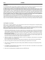
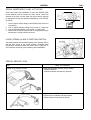
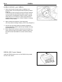
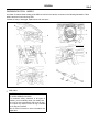
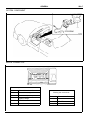
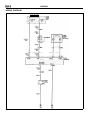
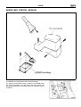
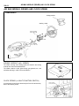
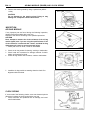
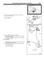
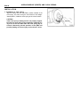
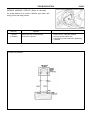
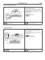
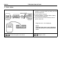
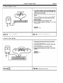
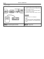
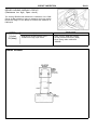
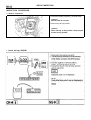
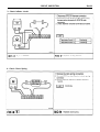
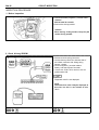
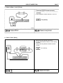
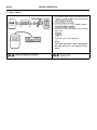
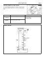
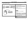
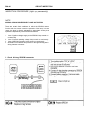
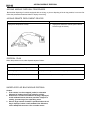
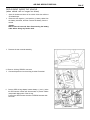
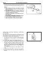
SUPPLEMENTAL
RESTRAINT
SYSTEM
(SRS AIRBAG)
Return To Main Table of Contents
GENERAL .............................................................................. 2
SRSCM (SRS Control Module) ......................................... 9
AIRBAG MODULE (DRIVER) AND CLOCK SPRING ........ 12
AIRBAG CONNECTORS ..................................................... 17
TROUBLESHOOTING ............................................................ 19
AIRBAG MODULE DISPOSAL ........................................... 46
56A-2
GENERAL
GENERAL
The supplemental restraint system (SRS) is designed to supplement the driver’s seat belt to help reduce the risk or severity
of injury to the driver by activating and deploying a drivers-side air bag in certain frontal collisions.
The SRS (Air-bag) consists of; a driver side air bag module located in the center of the steering wheel, which contains
the folded air-bag and an inflator unit: SRSCM (SRS control module) located under the rear console assembly, which
monitors the system, and an accelerometer which senses the vehicle deceleration an SRS SRI (Service reminder
Indicator) located on the cluster, which indicates the operational status of the SRS; a clock spring interconnection located
within the steering column; system wiring and wiring connector; and a knee bolster located under the steering column.
The impact sensing function of the SRSCM is carried out by electronic accelerometer that continuously measure the
vehicle’s acceleration and delivers a corresponding signal through amplifying and filtering circuitry to the microprocessor.
That is designed to occur in frontal or near-frontal impacts of moderate to severe force.
Only authorized service personnel should do work on or around the SRS components. Those service personnel should
read this manual carefully before starting any such work. Extreme care must be used when servicing the SRS, to avoid
injury to the service personnel (by inadvertent deployment of the air bag) or the driver (by rendering the SRS inoperative)
CUSTOMER CAUTIONS
Failure to carry out service operations in the correct sequence could cause the airbag system to unexpectedly deploy
during servicing, possibly leading to a serious accident.
Further, if a mistake is made in servicing the airbag system, it is possible the airbag may fail to operate when required.
Before performing servicing (including removal or installation of parts, inspection or replacement), be sure to read the
following items carefully, then follow the correct procedure described in the repair manual.
1. Work must be started after approx. 30 seconds or longer from the time the ignition switch is turned to the LOCK position
and the negative (-) terminal cable is disconnected from the battery. (The airbag system is equipped with a back-up
power source so that if work is started within 30 seconds of disconnecting the negative (-) terminal cable of the battery,
the airbag may be deployed.)
When the negative (-) terminal cable is disconnected from the battery, memory of the clock and audio systems will
be cancelled. So before starting work, make a record of the contents memorized by the audio memory system. Then
when work is finished, reset the audio system as before and adjust the clock.
2.
Malfunction symptoms of the airbag system are difficult to confirm, so the diagnostic codes become the most important
source of information when troubleshooting.
When troubleshooting the airbag system, always inspect the diagnostic codes before disconnecting the battery.
3.
Never use airbag parts from another vehicle. When replacing parts, replace them with new parts.
4.
Never attempt to disassemble and repair the airbag modules, SRSCM, Clock spring and Air-bag wiring harness
in order to reuse it.
5.
If the SRSCM or air-bag module have been dropped, or if there are cracks, dents or other defects in the case, bracket
or connector, replace them with new ones.
6. After work on the airbag system is completed, perform the SRS SRI check.
GENERAL
56A-3
SRSCM INDEPENDENT LAMP ACTIVATION
There are certain fault conditions in which the SRSCM (SRS
Control Module) cannot function and thus cannot control the
operation of the lamp. In these cases, the lamp is directly activated
by appropriate circuitry that operates independently of the SRSCM,
as follows:
1.
2.
3.
4.
Loss of ignition voltage supply to the SRSCM: lamp turned on
continuously
Loss of internal operating voltage: lamp turned on continuously
Loss of SRSCM operation: lamp turned on continuously.
SRSCM not connected: lamp turned on continuously through
shorting bar in wiring harness connector
CLOCK SPRING (in MULTI-FUNCTION SWITCH)
The steering wheel must be fitted correctly to the steering column
with the clock spring at the neutral position, otherwise cable
disconnection and other troubles may result. Refer to page 56A-13
of this manual concerning correct steering wheel installation.
SPECIAL SERVICE TOOL
Tool
Airbag wiring harness checker
Name and Description
Airbag wiring harness checker (0957A-34000)
- Harness inspection
- SRSCM inspection with dummy terminals
Deployment tool (0957A-34100)
- Deployment of undeployed Air-bag module
(When vehicle will not longer be driven)
56A-4
GENERAL
AIR-BAG MODULE (with AIRBAG)
1. When removing the air-bag module or handling a new
air-bag module, it should be placed with the pad top surface
facing up.
In this case, the twin-lock type connector lock lever should be
in the lock state and care should be taken to place it so the
connector will not be damaged. And do not store a steering
wheel pad on top of another one. (Storing the pad with its
metallic surface up may lead to a serious accident if the airbag
inflates for some reason.)
2.
Never measure the resistance of the airbag squib.
(This may cause the airbag to deploy, which is very dangerous.)
Store the air-bag module where the ambient temperature
remains below 93°C (200°F) without high humidity and away
from electrical noise.
4. When using electric welding, first disconnect the airbag connector (red color and 2 pins) under the steering column near
the MULTI-FUNCTION SWITCH connector before starting
work.
3.
SRSCM (SRS Control Module)
Install the SRSCM with the arrow on the SRSCM facing toward
the front of the vehicle.
GENERAL
56A-5
WARNING/CAUTION LABELS
A number of caution labels relating to the SRS are found in the vehicle, as shown in the following illustration. Follow
label instructions when servicing SRS.
If labels are dirty or damaged, replace them with new ones.
E
F
B
-
DAB ONLY
CAUTION
TO AVOID SERIOUS INJURY:
For maximum safety protection in all types of
crashes, you must always wear your safety belt.
Do not sit or lean unnecessarily close to the air bag.
Do not place any objects over the air bag or between
the air bag and yourself.
See the owner’s manual for further information and
explanation.
-
-
56A-6
GENERAL
B. DAB ONLY
Air bag system is normal if “SRS” lamp, in cluster
flashes approximately 6 times and then goes out
after ignition key is turned on.
However, if any of the following conditions occur the
system must be serviced.
1. “SRS” lamp does not light when key is turned on.
2. “SRS” lamp flashes or stays lit continuously.
3. The airbag has inflated.
Always fasten children in child-restraints placed in
the rear seat.
Rear seating positions are safer for children.
WARNING! failure to follow above instruction can
result in injury to you or other occupants and
children in the vehicle.
See “SRS” section in Owners Manual for more
information about airbag.
F. Danger! Poison. Keep out of the reach of children.
Contains sodium azide and potassium nitrate contents are poisonous and extremely flammable. Contact with acid, water, or heavy metals may produce
harmful and irritating gases or explosive compounds.
Do not dismantle, incinerate, bring into contact with
electricity of store at temperature exceeding (93.3”C)
200°F.
First aid: If contents are swallowed, induce vomiting.
For eye contact flush eye with water for 15 minutes.
If gases from acid or water contact are inhaled, seek
fresh air. In every case, get prompt medical attention.
For additional information, see material safety data
sheet (MSDS) for this product.
H. CAUTION: SRS
Before removal of steering gearbox, read service
manual, center front wheels and remove ignition
key.
Failure to do so may damage SRS clock spring and
render SRS system inoperative, risking serious driver
injury.
D. CAUTION: SRS
Before replacing steering wheel, read service manual,
center front wheels and align SRS clock spring
neutral marks.
Failure to do so may render SRS system inoperative, risking serious driver injury.
E. WARNING SRS
To help avoid personal injury due to unwanted
inflation do not service or dispose of this unit without
following instructions in the service manual.
G. CAUTION: SRS clock spring
This is not a repairable part. Do not disassemble or
tamper.
If defective, remove and replace entire unit per
service manual instructions.
Before replacement, read service manual, center
front wheels and align neutral marks.
Failure to follow instructions may render SRS system inoperative, risking serious driver injury.
GENERAL
56A-7
SYSTEM COMPONENT
SRSCM CONNECTOR
Connector pinout
Pin 1
Driver inflator, low side
Pin 2
Driver inflator, high side
Pin 3
Serial data input, output
Pin 7
Ignition voltage
Pin 9
SRS SRI
Pin 22,23 SRS SRI
Pin 10
Ground
Pin 24, 25
Shorting bar removal tab
Pin 14,15
Driver side inflator
Pin 18,19
Not used
Not used
GENERAL
WIRING DIAGRAM
IN ON OR START
SRSCM
SRSCM (SRS CONTROL MODULE)
The SRSCM is mounted below rear console assembly.
The electronic accelerometer which is located in the SRSCM sense
the vehicle deceleration for determining the firing instant and
discriminating between must-deploy and must-not-deploy impact
conditions.
56A-10
SRSCM
REMOVAL
CAUTION
Never attempt to disassemble or repair the SRSCM. If
faulty, replace it.
Do not drop or subject the SRSCM to impact or
vibration.
If denting, cracking, deformation, or rust are discovered in the SRSCM, replace it with a new SRSCM.
Discard the old one.
After deployment of an air bag, replace the SRSCM
with a new one.
Never use an ohmmeter on or near the SRSCM and use
only the Scan Tool.
1.
Disconnect the negative battery cable and keep it secure from
the battery
CAUTION
Wait at least 30 seconds after disconnecting the battery
cable before doing any further work.
2.
3.
Remove the rear console assembly,
Disconnect the SRSCM harness first before removing the
Air-bag mounting bolt.
4. Remove the SRSCM.
SRSCM
INSPECTION
1.
Check the SRSCM case and brackets for dents, cracks or
deformities.
2. Check connectors and the lock lever for damage, and terminals
for deformities.
CAUTION
If a dent, cracks, deformation or rust are discovered,
replace the SRSCM with a new one.
56A-11
56A-12
AIR-BAG MODULE (DRIVER) AND CLOCK SPRING
AIR BAG MODULE (DRIVER) AND CLOCK SPRING
COMPONENTS
Airbag module
steering wheel
AIR-BAG MODULE (with AIRBAG)
The inflater and bag of the airbag system are stored in the air-bag
module and cannot be disassembled.
The inflater contains a squib, igniter charge, gas generant, etc., and
will inflate the bag in case of a frontal collision.
CLOCK SPRING (in MULTI-FUNCTION SWITCH)
A clock spring is used as an electrical joint from the vehicle body
side to the steering wheel.
AIR-BAG MODULE (DRIVER) AND CLOCK SPRING
REMOVAL
CAUTION
1. Never attempt to disassemble or repair the air bag
module or clock spring.
If faulty, replace it.
2. Do not drop the air bag module or clockspring or allow
contact with water, grease or oil.
Replace it if a dent, crack, deformation or rust are
detected.
3. The air bag module should be stored on a flat surface
and placed so that the pad surface is facing upward.
Do not place anything on top of it.
4. Do not expose the air bag module to temperature over
93°C (200°F).
5. After deployment of an air bag, replace the clock
spring with a new one.
6. Wear gloves and safety glasses when handling an air
bag that has already deployed.
7. An undeployed air bag module should only be disposed of in accordance with the procedures
1.
Disconnect the negative battery cable and keep secure from
battery.
CAUTION
Wait at least 30 seconds after disconnecting the battery
cable before doing any further work.
2. Remove the air bag module mounting nut using a socket
wrench from the back side.
3. When disconnecting the connector of the clock spring from the
air bag module, press the air bag’s lock toward the outer side
to spread it open. Use a screwdriver, as shown in the figure, to
pry so as to remove the connector gently.
CAUTION
o When disconnecting the air bag module-clock spring
connector, take care not to apply excessive force to it.
o The removed air bag module should be stored in a
clean, dry place with the pad cover face up.
56A-13
56A-14
4.
AIR-BAG MODULE (DRIVER) AND CLOCK SPRING
Remove the steering wheel by using a special tool (0956111002).
09561
CAUTION
Do not hammer on the steering wheel. Doing so may
damage the collapsible column mechanism.
INSPECTION
AIR BAG MODULE
If any improper part are found during the following inspection,
replace the air bag module with a new one.
Dispose of the old one according to the specified procedure.
CAUTION
Never attempt to measure the circuit resistance of the air bag
module (squib) even if you are using the specified tester. If the
circuit resistance is measured with a tester, accidental air bag
deployment will result in serious personal injury.
1. Check pad cover for dents, cracks or deformities.
2. Check the air bag module for denting, cracking or deformation.
3. Check hooks and connectors for damage, terminals for deformities, and harness for binds.
4. Check air bag inflator case for dents, cracks or deformities.
5.
Install the air bag module to steering wheel to check fit or
alignment with the wheel.
CLOCK SPRING
If, as a result of the following checks, even one abnormal point is
discovered, replace the clock spring with a new one.
1. Check connectors and protective tube for damage, and terminals for deformities.
Conne
AIR-BAG MODULE (DRIVER) AND CLOCK SPRING
2. Visually check the case and the gears for damage.
3.
Check for continuity between No.1 connector of the clock
spring and connectors No.2.
Limit : Continuity
4.
Check of resistance between the terminals.
(1) Join the No.4 connector of the clock spring to the Airbag
wiring harness checker.
(2) Check continuity between terminals 1 and 2 of the Airbag
wiring harness checker.
Limit : Continuity
(3) Join the No.4 and No. 5 connectors of clock spring to the
Airbag wiring harness checker.
(4) Check continuity between terminals 1 and 2 of the Airbag
wiring harness checker.
Limit : No continuity
56A-15
56A-16
AIR-BAG MODULE (DRIVER) AND CLOCK SPRING
INSTALLATION
1. Installation of clock spring
Align the mating mark and “NEUTRAL” position indicator of the
clock spring, and, after turning the front wheels to the straightahead position, install the clock spring to the column switch.
CAUTION
If the clock spring’s mating mark is not properly aligned,
the steering wheel may not be completely rotational during a turn, or the flat cable within the clock spring may be
severed, obstructing normal operation of the SRS and
possibly leading to serious injury to the vehicle’s driver.
AIR-BAG CONNECTORS
56A-17
CONNECTORS
All wiring in the airbag system is wrapped in yellow type to distinguish it from others. For ensuring high reliability, air-bag
connectors have special functions and specifically designed. The connectors use gold-plated terminals.
1. SRS control Module
- Twin-lock Mechanism
- Anti-deploy Mechanism
- Electrical Connection check Mechanism
Anti-deploy mechanism
Twin-lock Mechanism
Anti-deploy mechanism
Twin-lock Mechanism
2. Driver Air-bag
- Twin lock Mechanism
- Anti-deploy Mechanism
Anti-deploy mechanism
Twin-lock Mechanism
Electrical connection check mechanism
SRS Control Module Connector (SRSCM Connector)
SRSCM Connector is designed with 3 security systems for preventing unexpected deployment because of poor
connections.
1. Twin Lock mechanism secures the locking of the terminal by locking device to prevent terminal from coming out.
2. Anti-deploy mechanism to prevent unexpected deployment by shortening of the two squib terminals.
3. Electrical Connection check mechanism is designed for finding poor connections at the SRSCM connector.
If it occurs SRS SRI (Service Reminder Indicator) lights up permanently.
AIR-BAG CONNECTORS
56A-18
Driver Air-Bag Module (DAB)
Two security mechanism of the DAB is twin-lock mechanism and anti-deploy mechanism. The anti-deploy mechanism
prevents unexpected deployment by the shortening of the two squib terminals.
The twin-lock mechanism connectors (male and female) are fastened locked by two locking devices to increase connection
reliability. If the primary lock is incomplete, ribs interfer and prevent the secondary lock.
Twin lock mechanism,
Anti deploy mechanism
Connector is
UNLOCKED
Secondary lock
Connector is
Shortening bar
TROUBLESHOOTING
DIAGNOSIS SYSTEM
SERVICE REMINDER INDICATOR CHECK
When the ignition switch is turned on, check that the SRS SRI goes
ON for 6 seconds, if the SRI is not illuminated immediately after the
ignition is turned ON, a failure in the area of SRI circuit has
occurred .
Exception : If an “Ignition input voltage too low”
(Fault Code#7) is detected, the SRI will turn off at
the end of the current ignition cycle.
The fault will also be recorded in the history fault
code #57.
56A-19
56A-20
TROUBLESHOOTING
SCAN TOOL CHECK
1. Turn the ignition OFF.
2. Connect the scan tool to the data link connector in the fuse box.
3. Connect the power-source terminal of the scan tool to the
cigarette lighter socket.
4. Turn the ignition ON.
5. Use the scan tool to check the diagnostic trouble codes.
6. Complete the repair or correction of the problems, after turning
OFF the ignition switch; then erase the stored diagnostic
trouble codes using the SCAN TOOL.
7. Disconnect the scan tool.
TROUBLESHOOTING
Diagnostic Trouble Code(DTC) Chart
56A-22
TROUBLESHOOTING
SERVICE DATA
SCAN TOOL (SCAN TOOL) DISPLAY
DESCRIPTION OF TROUBLE CODE
01. CRASH NUMBERS
**
Numbers of airbag activation (inflation)
02. SRI STATUS
ON or OFF
The ON-OFF status of service reminder indicator
03. SRI TIME
*** MIN.
The driving time after service reminder indicator “ON” is
recorded for fourty two hours by the minutes interval.
04.1G CYCLE
***
The engine starting numbers after service reminder
indicator “ON” can be recorded 100 times.
NOTE
The above service data information can be recorded in non-volatile memory by the SRSCM in case of deployment
event, for retrieval at a later time.
56A-23
TROUBLESHOOTING
AIR-BAG MODULE CIRCUIT (Short to Ground)
The Air-Bag Module circuit consists of SRSCM, spiral cable (clock
spring), driver side airbag module.
1 (Active)
51 (History)
Trouble cause
Symptom
Code No.
DAB (Driver side air-bag module)
circuit short to ground.
WIRING-DIAGRAM
o
o
o
o
Short circuit in DAB wire harness
Air-bag module malfunction.
Clock spring cable malfunction (DAB only)
SRSCM.
56A-24
TROUBLESHOOTING
INSPECTION PROCEDURE
1. Before inspection
1. Disconnect battery negative (-) terminal cable
Caution !
Wait at least 30 seconds.
2. Remove the air-bag module.
Caution !
When storing air-bag module, keep the
pad surface facing upward.
2. Check Air-bag SRSCM
1. Disconnect clock spring connector.
2. Connect dummy-terminal to harness side of the
inflator connector with SRS harness checker.
3. Connect negative (-) terminal cable to battery,
and wait at least 5 seconds.
4. Connect the SCAN TOOL terminal, and turn
ignition switch ON.
Diagnostic code 1 is not displayed.
NOTE
Code other than code 1 may be displayed
at this time, but this is not relevant to this
check.
TROUBLESHOOTING
56A-25
3. Check inflator circuit (Driver)
AIR-BAG HARNESS
1. Disconnect SRSCM harness connector
and clock spring connector.
2. Connect SRS harness checker to the SRSCM
harness connector and clock spring harness
side connector.
3. Check continuity between terminals 11, 12 and
body ground.
No continuity
Replace SRSCM
Replace Air-bag harness
4. Check clock spring
1. Disconnect DAB and clock spring connector.
2. Connect the SRS harness checker to clock
spring connector.
3. Check continuity between terminals 5, 6 and
body ground.
Replace clock spring
TROUBLESHOOTING
56A-26
5. Check Inflator
1. Turn ignition switch to lock, and disconnect the
negative (-) terminal cable from battery and wait
at least 30 seconds.
2. Connect inflator connector.
3. Connect negative (-) terminal cable to battery
and wait at least 5 seconds.
4. Connect the SCAN TOOL terminal, and turn
ignition switch ON.
Diagnostic code 1 is not displayed.
NOTE
Code other than code 1 may be displayed
at this time, but this is not relevant to this
check
Connect all system and recheck
Replace DAB
56A-27
CIRCUIT INSPECTION
AIR-BAG MODULE CIRCUIT
(Short to Battery +)
The DAB circuit consists of Air-bag SRSCM, clock spring and the
Air-bag module.
Code No.
Symptom
2 (Active)
52 (History)
DAB (Driver side Air-bag modulator) circuit
short to Battery + (12V)
WIRING DIAGRAM
Trouble Area
o Short circuit in DAB wire harness
(to battery + (12V))
o Air-bag modulator malfunction
o Clock spring cable malfunction
o SRSCM
56A-28
CIRCUIT INSPECTION
INSPECTION PROCEDURE
1. Before inspection
1. Disconnect battery negative (-) terminal cable
Caution !
Wait at least 30 seconds.
2. Remove the air-bag module.
Caution !
When storing air-bag module, keep the pad
surface facing upward.
2. Check Air-bag SRSCM
CIRCUIT INSPECTION
3. Check inflator circuit
4. Check Clock Spring
56A-29
56A-30
CIRCUIT INSPECTION
5. Check Inflator
1. Turn ignition switch to lock, and disconnect the
negative (-) terminal cable from battery and wait
2. Connect inflator connector.
3. Connect negative (-) terminal cable to battery
and wait at least 5 seconds.
4. Connect the SCAN TOOL terminal, and turn
Diagnostic code 2 is not displayed.
NOTE
Code other than code 2 may be displayed at
this time, but this is not relevant to this
check.
56A-31
CIRCUIT INSPECTION
DRIVER AIR-BAG MODULE CIRCUIT
(Resistance too high, Open circuit)
The Air-bag SRSCM shall measure the resistance of the DAB
(Driver Air-Bag module) to detect a resistance which lies outside
the allowed range. Do not attempt to measure the resistance of
DAB squib.
Trouble cause
Symptom
DAB (Driver Air-Bag module) circuit
resistance too high, open circuit.
WIRING DIAGRAM
o
o
o
o
Open circuit in DAB wire harness
Air-bag module malfunction (DAB)
Clock spring cable malfunction
SRSCM.
CIRCUIT INSPECTION
INSPECTION PROCEDURE
1. Before inspection
1. Disconnect battery negative (-) terminal cable
Caution !
Wait at least 30 seconds.
2. Remove the air-bag module.
Caution !
When storing air-bag module, keep the pad
surface facing upward.
2. Check Air-bag SRSCM
CIRCUIT INSPECTION
3. Check Inflator circuit
4. Check Clock Spring
56A-33
56A-34
CIRCUIT INSPECTION
5. Check Inflator
1. Turn ignition switch to lock, and disconnect the
negative (-) terminal cable from battery and wait
at least 30 seconds.
2. Connect inflator connector.
3. Connect negative (-) terminal cable to battery
and wait at least 5 seconds.
4. Connect the scan tool terminal, and turn ignition
switch ON.
Diagnostic code 3 is not displayed
NOTE
Code other than code 3 may be displayed at
this time, but this is not relevant to this
check.
CIRCUIT INSPECTION
56A-35
DRIVER AIR-BAG MODULE CIRCUIT
(Resistance too Low, Short Circuit)
The Air-bag SRSCM shall measure the resistance of the DAB
(Driver-Air-Bag module) to detect a resistance which lies outside
the allowed range. Never attempt to measure the resistance of the
DAB squib.
Symptom
Code No.
5 (Active)
55 (History)
DAB (Driver Air-Bag module) circuit
resistance too low, short circuit.
WIRING DIAGRAM
Trouble Area
o Short circuit in DAB wire harness
o Air-bag module malfunction (DAB)
o Clock spring cable malfunction
o SRSCM.
56A-36
CIRCUIT INSPECTION
INSPECTION PROCEDURE
1. Before inspection
1. Disconnect battery negative (-) terminal cable
Caution !
Wait at least 30 seconds.
2. Remove the air-bag module.
Caution !
When storing air-bag module, keep the pad
surface facing upward.
2. Check Air-bag SRSCM
1. Disconnect clock spring connector.
2. Connect dummy-terminal to harness side of
the inflator connector with Airbag wiring
harness checker.
3. Connect negative (-) terminal cable to
battery, and wait at least 5 seconds.
4. Connect the SCAN TOOL terminal, and turn
ignition switch ON.
Diagnostic code 5 is not displayed.
NOTE
Code other than code 5 may be displayed at
this time, but this is not relevant to this
check.
CIRCUIT INSPECTION
56A-37
3. Check Inflator circuit (Driver)
4. Check Clock Spring
1. Remove the clock spring connectors.
2. Connect SRS harness checker to clock spring
connector
3. Check continuity between checker terminal
5 and 6
No continuity
56A-38
CIRCUIT INSPECTION
5. Check Inflator
1. Turn ignition switch to lock, and disconnect the
negative (-) terminal cable from the battery and
cable to battery
4. Connect the scan tool terminal, and turn ignition
switch ON.
Diagnostic code 5 is not displayed
NOTE
Code other than code 5 may be displayed at
this time, but this is not relevant to this
check
CIRCUIT INSPECTION
56A-39
IGNITION POWER VOLTAGE CIRCUIT
The Air-bag SRSCM shall measure the voltage at the ignition input
to detect an operating voltage which is out of the normal operating
range.
Symptom
Code No.
7 (Active)
57 (History)
Ignition input voltage too low
8 (Active)
58 (History)
Ignition input voltage too high
WIRING DIAGRAM
Trouble Area
o Fuse 9 in dash fuse box
o Air-bag harness
o Charging system
56A-40
CIRCUIT INSPECTION
1. Power source
1. Disconnect battery negative (-) terminal cable
Caution !
Wait at least 30 seconds
AIR-BAG HARNESS
2. Turn ignition switch to LOCK.
3. Disconnect SRSCM connector.
4. Connect SRS harness checker to SRSCM connector and connect battery negative (-) terminal
cable.
5. Turn ignition switch to ON (Engine stop).
6. Measure voltage between checker terminal 16
and body ground.
9.0 V to 16.0 V
2. Ground connection
CIRCUIT INSPECTION
56A-41
3. Check SCAN TOOL display
1. Remove battery negative (-) terminal cable.
2. Connect SRSCM connector.
3. Connect battery negative (-) terminal cable.
4. Turn ignition switch ON and wait at least 30
second, and check that the air bag SRS SRI
goes off
5. Turn ignition switch to lock.
6. Connect SCAN TOOL and turn ignition switch
ON.
Diagnostic code 7, 8 is not displayed
NOTE
If the fault disappears or is corrected between
two ignition cycles (i.e. while the Air-bag
SRSCM is off), the warning lamp shall remain
on for 15 second after the bulb check in the
sub sequent ignition cycle.
CIRCUIT INSPECTION
56A-42
SERVICE REMINDER INDICATOR CIRCUIT
The SRI is located on the cluster.
When the air bag system is normal, the SRI flashes for approx. 6
seconds after the ignition switch is turned ON, and then turns off
automatically.
If there is a malfunction in the air bag system, the SRI lights up to
inform the driver of the abnormality.
The SRSCM shall measure the voltage at the air-bag SRI (Malfunction Indicator Light) output pin, both when the lamp is on and when
the lamp is off, to detect whether the commanded state matches
the actual state.
13 (Active)
63 (History)
Trouble Area
Symptom
Diag. No.
SRS SRI short to ground or to battery
voltage, open circuit
o SRI circuit
o SRSCM
SRI does not light up
GO TO 43
SRI light up permanently
GO TO 44
WIRING DIAGRAM
CIRCUIT INSPECTION
56A-43
INSPECTION PROCEDURE (DOES NOT LIGHT UP)
1. Check Air-bag Fuse
1. Remove fuse 10 and 18 located in dash fuse box
2. Check continuity of fuse 10 and 18.
Continuity
2. Check SRS SRI circuit
56A-44
CIRCUIT INSPECTION
INSPECTION PROCEDURE (Light up permanently)
NOTE
AIR-BAG SRSCM INDEPENDENT LAMP ACTIVATION
There are certain fault conditions in which the SRSCM cannot
function and thus cannot control the operation of the lamp. In these
cases, the lamp is directly activated by appropriate circuitry that
operates independently of the SRSCM as follows:
1.
Loss of ignition voltage supply to the SRSCM: lamp turned on
continuously
2. Loss of internal operating voltage: lamp turned on continuously.
3. Loss of SRSCM operation: lamp turned on continuously.
4. SRSCM not connected: lamp turned on through shorting bar in
wiring harness connector.
1. Check Air-bag SRSCM connector
CIRCUIT INSPECTION
SRSCM MALFUNCTION
The SRSCM shall also cyclically monitor the following:
a) Functional readiness of the firing circuit activation transistors (driver and passenger side)
b) Adequacy of deployment energy reserves (driver and
passenger-side)
c) Safing sensor integrity: detection of faulty closure (longer
than 4 seconds)
d) Plausibility of accelerometer signal
e) Operation of SRSCM components (AID-converter,
etc.)
The timely completion of all tests is monitored by a separate
hardware watchdog. During normal operation, the watchdog is
triggered periodically by the SRSCM; if the SRSCM fails to trigger
the watchdog, the watchdog will reset the SRSCM and activate the
SRI (Service Reminder Indicator)
56A-45
AIR BAG MODULE DISPOSAL
AIR BAG MODULE DISPOSAL PROCEDURES
Before either disposing of a vehicle equipped with an air bag, or prior to disposing of the air bag module, ‘be sure to first
follow the procedures described below to deploy the air bag.
AIR BAG REMOTE DEPLOYMENT DEVICES
Use
Tool, Number, Name
Deployment tool(0957A-34100)
o
Deployment inside the vehicle (when vehicle
will not longer be driven)
DISPOSAL PLAN
When the problem occurs, take disposal steps as follows.
CASE
DISPOSAL PLAN
Abnormal problems in air bag module
Return to HMC dealer
Car scrapping
Deploy the air bag module in the scrapper yard with SST
Crash (Deployed)
Service station disposes the Air-bag module
UNDEPLOYED AIR BAG MODULE DISPOSAL
Caution
1. If the vehicle is to be scrapped, junked, or otherwise
disposed of, deploy the air bag inside the vehicle.
2. Since there is a loud noise when the air bag is deployed,
avoid residential areas whenever possible. If anyone is
nearby, give warning of the impending noise.
3. Since a large amount of smoke is produced when the air
bag is deployed, select a well-ventilated site. Moreover,
never attempt the test near a fire or smoke sensor.
AIR BAG MODULE DISPOSAL
DEPLOYMENT INSIDE THE VEHICLE
(when vehicle will no longer be driven)
1. Open all windows and doors of the vehicle. Move the vehicle to
an isolated spot.
2. Disconnect the negative (-) and positive (+) battery cables from
the battery terminals, and then remove the battery from the
vehicle.
Caution
Wait at least 30 seconds after disconnecting the battery
cable before doing any further work.
3.
Remove the rear console assembly.
4. Remove Air-bag SRSCM connector
5. Connect disposal tool to the air bag checker R-terminal.
6. Connect SRS air bag adapter harness battery (+) and (-) when
the SRS harness checker still disconnected, to prevent sudden
unexpected deployment of the air bag.
Connect the SRS harness checker to SRSCM harness side
connector.
56A-47
56A-48
AIR BAG MODULE DISPOSAL
7. At location as far away from the vehicle as possible, press the
pugh button (removed from the vehicle) to deploy the air bag.
Caution
1. Before deploying the air bag in this manner, first check
to be sure that there is no one in or near the vehicle.
Wear safety glasses.
2. The inflator will be quite hot immediately following the
deployment, so wait at least 30 minutes to allow it to
cool before attempting to handle it.
Although not poisonous, do not inhale gas from air
bag deployment.
See Deployed Air Bag Module Disposal Procedures
for post-deployment handling instructions.
3. If the air bag fails to deploy when the procedures
above are followed, do not go near the module.
DEPLOYED AIR BAG MODULE DISPOSAL
PROCEDURES
After deployment, the air bag module should be disposed of in the
same manner as any other scrap parts, except that the following
points should be carefully noted during disposal.
1. The inflator will be quite hot immediately following deployment,
so wait at least 30 minutes to allow it to cool before attempting
to handle it.
2. Do not put water or oil on the air bag after deployment.
3. There may be, adhered to the deployed air bag module,
material that could irritate the eyes and/or skin, so wear gloves
and safety glasses when handling a deployed air bag module.
IF DESPlTE THESE PRECAUTIONS, THE MATERlAL DOES,
GET INTO THE EYES OR ON THE SKIN, IMMEDIATELY
RINSE THE AFFECTED AREA WITH A LARGE AMOUNT OF
CLEAN WATER.
IF ANY IRRITATION DEVELOPS, SEEK MEDICAL ATTENTION.
4. Tightly seal the air bag module in a strong vinyl bag for disposal.
5. Be sure to always wash your hands after completing this
operation.
vinyl