1
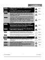
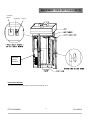
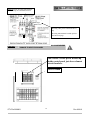
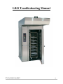
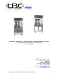
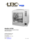
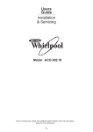
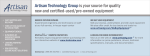
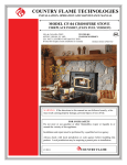
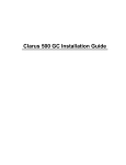
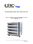
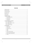
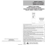
A
MODELS LRO-1E and LRO-2E
Electric Roll-in Rack Ovens
Installation and Operations Manual
REV 05/2011
READ FIRST
THIS MANUAL MUST BE RETAINED FOR FUTURE REFERENCE. READ, UNDERSTAND
AND FOLLOW THE INSTRUCTIONS AND WARNINGS CONTAINED IN THIS MANUAL.
FOR YOUR SAFETY
DO NOT STORE OR USE GASOLINE OR OTHER FLAMMABLE VAPORS AND LIQUIDS IN
THE VICINITY OF THIS OR ANY OTHER APPLIANCE.
POST IN A PROMINENT LOCATION:
I
WARNING: IMPROPER INSTALLATION, ADJUSTMENT, ALTERATION, SERVICE OR
MAINTENANCE CAN CAUSE PROPERTY DAMAGE, INJURY OR DEATH. READ THE
INSTALLATION, OPERATING AND MAINTENANCE INSTRUCTIONS THOROUGHLY
BEFORE INSTALLING OR SERVICING THIS EQUIPMENT.
DANGER
POTENTIALLY HAZARDOUS SITUATION WHICH, IF NOT
AVOIDED, COULD RESULT IN DEATH.
WARNING
POTENTIALLY HAZARDOUS SITUATION WHICH, IF NOT
AVOIDED, COULD RESULT IN DEATH OR SERIOUS INJURY.
CAUTION
POTENTIALLY HAZARDOUS SITUATION WHICH, IF NOT
AVOIDED, MAY RESULT IN MINOR OR MODERATE INJURY.
NOTICE
Helpful operation and installation instructions and tips are
present.
Model #:
Purchased From:
Serial #:
Location:
Date Purchased:
Date Installed:
Purchase Order #:
For Service, Call:
ETL File 3028821
2
Rev 6-2010
TABLE OF CONTENTS
CHAPTER
PAGE
1.
TABLE OF CONTENTS ............................................................................... 3
2.
WARNING..................................................................................................... 4
3.
EQUIPMENT DESCRIPTION ...................................................................... 7
4.
INSTALLATION INSTRUCTIONS ............................................................. 10
5.
EMERGENCY OPERATION........................................................................ 17
6.
GENERAL OPERATION.............................................................................. 18
7.
PROGRAMMING.......................................................................................... 19
8.
GENERAL MAINTENANCE ....................................................................... 20
9.
SAFETY CONSIDERATIONS ..................................................................... 25
10. ILLUSTRATED PARTS BREAKDOWN..................................................... 26
11. WIRING DIAGRAMS................................................................................... 36
12. RESISTANCE CHARTS ............................................................................... 39
13. TROUBLESHOOTING ................................................................................. 40
14. WARRANTY………………………………………………………………...45
ETL File 3028821
3
Rev 6-2010
WARNINGS
WARNING
THE WATER FROM THE STEAM DRAIN OUTLET IS EXTREMELY
HOT AND MAY CAUSE SERIOUS BURNS.
PG. 7
NOTICE
Left rear drain point is provided. Route to a floor drain. A 1”
gap must be provided between oven drain and floor drain.
PG. 7
WARNING
WIRES ENTERING THE DISCONNECT MAY STILL BE LIVE EVEN
WHEN THE SWITCH IS TURNED OFF. SWITCH THE MAIN BREAKER
AT THE WALL TO “OFF” WHEN SERVICING THE OVEN
TO REDUCE THE RISK OF FIRE, THE APPLIANCE IS TO BE
MOUNTED ON FLOORS OF NON-COMBUSTIBLE CONSTRUCTION
WITH NON-COMBUSTABLE FLOORING AND SURFACE FINISH AND
WITH NO COMBUSTIBLE MATERIAL AGAINST THE UNDERSIDE
THEREOF, OR ON NON-COMBUSTABLE SLABS OR ARCHES
HAVING NO COMBUSTIBLE MATERIAL AGAINST THE UNDERSIDE.
SUCH CONSTRUCTION SHALL EXTEND A MINIMUM OF 12-INCHES
BEYOND THE EQUIPMENT ON ALL SIDES. See fig. 1
CAUTION
PG.
8,19
PG. 10
Fig. 1
Floor
Construction
ETL File 3028821
4
Rev 6-2010
WARNINGS CONT’D
DO NOT UNLOAD THE RACK FROM THE OVEN WHILE THE
CARRIER IS IN THE LIFT POSITION. LOADED RACKS CAN BE
EXTREMELY HEAVY.
PG. 17
WARNING
DO NOT REMOVE A FLAMING PRODUCT FROM THE OVEN.
SEVERE BURNS AND PROPERTY DAMAGE CAN RESULT.
PG. 17
CAUTION
THIS APPLIANCE, WHEN INSTALLED, MUST BE ELECTRICALLY
GROUNDED IN ACCORDANCE WITH LOCAL CODES, OR IN THE
ABSENCE OF LOCAL CODES, WITH THE NATIONAL ELECTRICAL
CODE, ANSI/NFPA 70-1996.
PG. 10
FOR INSTALLATION IN CANADA THE INSTALLATION MUST BE IN
ACCORDANCE WITH CAN/CGA-B149.1&2 OF THE INSTALLATION
CODE, AND LOCAL CODES WHERE APPLICABLE. ALL ELECTRIC
WIRING MUST BE IN ACCORDANCE WITH THE CURRENT
CANADIAN ELECTRICAL CODE, C22.1 PART 1. GROUNDING THIS
APPLIANCE MUST CONFORM TO CANADIAN ELECTRICAL CODE,
CSA C22.2.
PG. 11
INSTALLATION OF THE UNIT MUST BE DONE BY PERSONNEL
QUALIFIED TO WORK WITH ELECTRICITY AND PLUMBING
IMPROPER INSTALLATION CAN CAUSE INJURY TO PERSONNEL
AND /OR DAMAGE TO EQUIPMENT. UNIT MUST BE INSTALLED IN
ACCORDANCE WITH ALL APPLICABLE CODES.
PG. 11
DO NOT ALLOW ANY PART OF YOUR BODY TO BE UNDER THE
OVEN DURING THE LIFTING PROCESS. KEEP EVERYONE CLEAR
FROM THE OVEN IF IT SHOULD FALL.
PG. 11
It is imperative that a mechanical exhauster is installed, and a
pressure sensitive switch is installed at the collar of the hood. If a
negative draw of 0.6 is not achieved, the burner will not come on.
PG. 14
NOTICE
No other exhaust systems may be connected to this system. Do not
try to vent or exhaust another appliance into this hood.
PG. 14
WARNING
WHEN REMOVING THE RACK OR PRODUCT FROM THE RACK
WEAR OVEN MITTS TO AVOID SERIOUS BURNS.
PG. 17
NOTICE
Always ensure the grease filters supplied with the oven are used.
Replacement filters may be ordered from an LBC Bakery service
representative.
PG. 15
CAUTION
IF BLOWER ROTATION IS INCORRECT, IT WILL CAUSE SEVERE
DAMAGE TO HEAT EXCHANGER
PG. 16
CAUTION
CAUTION SHOULD BE TAKEN WHEN ENCLOSING HOOD TO
CEILING AND OVEN IS UNDER A FIRE SPRINKLER; HOOD
EXHAUST STACK WILL EMIT HEAT.
PG. 8
WARNING
CAUTION
WARNING
WARNING
NOTICE
ETL File 3028821
5
Rev 6-2010
WARNINGS CONT’D
WARNING
NOTICE
NOTICE
WARNING
NOTICE
NOTICE
NOTICE
WARNING
NOTICE
THIS LBC BAKERY OVEN PRODUCES HUMIDITY THAT CAN CAUSE
THE INTERIOR FLOORING AND ADJACENT EXTERIOR FLOORING
TO BECOME SLIPPERY. USE EXTREME CAUTION WHEN WALKING
ON A WET OR DAMP FLOOR.
PG. 18
The ambient temperature outside the oven should not exceed 104° F
(40° C). This includes the temperature of the air above and around
the oven.
PG. 18
During the first few hours of operation you may notice a small
amount of smoke coming off of the oven, and a faint odor from the
smoke. This is normal for a new oven and will disappear after the
first few hours of use.
PG. 18
WHEN THE LOADING DOOR IS OPENED, HOT AIR AND STEAM ARE
RELEASED FROM THE OVEN INTERIOR. TO AVOID BURNS OPEN
DOOR SLOWLY AND KEEP YOUR FACE AND HANDS CLEAR OF
THE OPENING. ALL INTERIOR SURFACES ARE VERY HOT. DO NOT
TOUCH ANYTHING WITHOUT OVEN MITTS.
PG. 18
Service on this, or any other, LBC BAKERY appliance must be
performed by qualified personnel only. Consult your authorized
service agency directory or call the factory at 1-888-722-5686 or go
to WWW. LBCBAKERY.COM for the service agent nearest you.
PG. 20
To maintain optimum safety and performance for LBC BAKERY
oven models LRO-1E & LRO-2E, it is recommended that a program
of scheduled periodic maintenance be implemented. It is the sole
responsibility of the user to establish, schedule and enforce such a
program. Although the actual service interval will vary depending on
the environment in which the equipment is operating, it is
recommended the following be done by an LBC BAKERY authorized
service agency at least every 6 months.
PG. 20
For periodic maintenance and repairs, electrical diagrams are
included in this manual and with the oven (on the back of the control
door).
PG. 20
SINCE RESETS FOR THE CIRCULATION BLOWER MOTOR AND THE
LIFTER MOTOR / ROTATOR MOTOR ARE AUTOMATIC, ALL POWER
TO THE OVEN MUST BE TURNED OFF BEFORE SERVICING.
PG. 21
If shutter settings are to be adjusted differently than the
recommended factory settings, the best results will be obtained if
you; (A) Start with the factory settings; (B) Close shutters to lighten
a product in a given area- do not open shutters to darken a product;
(C) Do not move a shutter more than 1/32” or 1mm (see step gauge
and shutter setting illustration) at any one time; (D) Be sure all
settings for left hand shutters match those for right hand shutters;
and (E) Do not adjust more than two shutters per side per time (four
shutters total).
ETL File 3028821
6
PG. 21
Rev 6-2010
EQUIPMENT DESCRIPTION
Data Plate
On this plate you will find the oven model, serial number, electrical ratings, (BTU’s, and gas type for gas ovens),
and clearance specification. Data plate is located behind the controller door on component cover.
Exterior Construction
The LRO-1E exterior dimensions are 55” (139.7 cm) wide x 105” (266.7 cm) high x 51” (129.5 cm) deep at the
base.
The LRO-2E exterior dimensions are 72” (182.9 cm) wide x 105” (265.4 cm) high x 62” (157.5 cm) deep at the
base.
The Top, Front, Back, and Sides are constructed of stainless steel with 5 inches of insulation.
Floor level loading.
Type I or Type II hood with single point exhaust connection complying with Uniform Mechanical Code and
NFPA 96: State, County and local code may vary; always check with local code officials.
The oven door is constructed of stainless steel with a full height single pane window and an interior releasing
mechanism.
Interior Construction
The LRO-1E cavity dimensions are 28” (92.71 cm) wide x 75” (190.5 cm) high x 39” (99.06 cm) deep at its
deepest point. The interior is constructed of stainless steel.
The LRO-2E cavity dimensions are 40” (92.71 cm) wide x 75” (190.5 cm) high x 50” (99.06 cm) deep at its
deepest point. The interior is constructed of stainless steel.
Smooth and simple rack loading and unloading.
Gentle rack lift and rotation protects delicate products.
The rack is designed to hold up to twenty 18”x 26” sheet pans.
A built in steam generator produces steam quickly.
Fully adjustable airflow for even cooking.
Controls
Large digital display which is easy to understand and operate.
Icon-driven (touch) panel allows for easy operation.
Pre-Programmable Product Selections.
Heat Loss Compensation for consistent baking.
Technical
The oven requires a 208/240 VAC three-phase power supply and a 115 VAC single phase power supply for
controls.
The oven requires no clearance from combustible wall construction.
WARNING
THE WATER FROM THE STEAM DRAIN OUTLET IS EXTREMELY
HOT AND MAY CAUSE SERIOUS BURNS.
Steam Drain Outlet
Water exits the steam generating system through this outlet It is located at the lower right-hand jamb or left rear
corner of the oven.
NOTICE
ETL File 3028821
Left rear drain point is provided. Remove the plug from
the location required and route to a floor drain. A 1” gap
must be provided between oven drain and floor drain.
7
Rev 6-2010
EQUIPMENT DESCRIPTION CONT’D
Floor Drain
This drain (customer supplied) receives the excess water from the steam generating system.
Rack Carrier
When the loading door is closed, the rack carrier lifts and rotates the oven rack.
Rack Stop
The two rack stops are located on the carrier and secure the oven rack in place during baking. The leading
edge of the forward stop must be manually flipped down to unload the oven rack. The stop will
automatically return to the up (loading) position when the rack is removed.
Hood
Steam and burner exhaust is discharged into the hood. Grease is channeled to and collected in a grease
cup for later removal.
Hood Exhaust
Cooking fumes pass through a duct to the hood exhaust outlet. A customer-supplied exhaust blower is
required. The hood can be wired to the external device terminals in the service box. This insures the hood
is on whenever the oven is on. The “POWER” switch on the oven control panel activates the blower. The
blower must be running before the oven will operate. A factory installed airflow switch disables heat
until airflow exists.
120V Circuit Breakers
Power to run the control panel and hood blower can be disconnected at these points. Switch to “OFF”
when servicing oven or blower.
WARNING
WIRES ENTERING THE DISCONNECT MAY STILL BE LIVE EVEN
WHEN THE SWITCH IS TURNED OFF. SWITCH THE MAIN
BREAKER AT THE WALL TO “OFF” WHEN SERVICING THE
OVEN
3-Phase Circuit Breaker
This disconnect provides short circuit protection for the circulation blower motor. Switch to “OFF” when
servicing the oven.
Element Circuit Breakers
There are circuit breakers installed to provide short circuit protection for the elements.
Main Power Connection
A 3-pole terminal block located in the upper control panel for the incoming high voltage power
connection. See Page 14
Control Connection
A 2-pole terminal block and 1-pole circuit breaker is located above the controls for power hook up for the
controls. See Page 14
Hood Supply
A 1-pole circuit breaker is provided to supply power to the ventilator hood.
CAUTION
CAUTION SHOULD BE TAKEN WHEN ENCLOSING HOOD TO
CEILING AND OVEN IS UNDER A FIRE SPRINKLER; HOOD
EXHAUST STACK WILL EMIT HEAT.
ETL File 3028821
8
Rev 6-2010
EQUIPMENT DESCRIPTION CONT’D
Circulation
Blower
Vent Blower
Controls
Element
circuit
breakers
Interior Door Release
This door release allows the door to be opened from inside the oven.
ETL File 3028821
9
Rev 6-2010
INSTALLATION INSTRUCTIONS
CAUTION
TO REDUCE THE RISK OF FIRE, THE APPLIANCE IS TO BE
MOUNTED ON FLOORS OF NON-COMBUSTIBLE
CONSTRUCTION WITH NON-COMBUSTABLE FLOORING AND
SURFACE FINISH AND WITH NO COMBUSTIBLE MATERIAL
AGAINST THE UNDERSIDE THEREOF, OR ON NONCOMBUSTABLE SLABS OR ARCHES HAVING NO
COMBUSTIBLE MATERIAL AGAINST THE UNDERSIDE. SUCH
CONSTRUCTION SHALL EXTEND A MINIMUM OF 12-INCHES
BEYOND THE EQUIPMENT ON ALL SIDES. See fig. 1 Page 4.
Receiving the Oven
Upon receipt, check for freight damage, both visible and concealed. Visible damage should be noted
on the freight bill at the time of delivery and signed by the carrier's agent. Concealed loss or damage
means loss or damage which does not become apparent until the merchandise has been unpacked. If
concealed loss or damage is discovered upon unpacking, make a written request for inspection by the
carrier's agent within 15 days of delivery. All packing material should be kept for inspection. Do not
return damaged merchandise to LBC Bakery Equipment. File your claim with the carrier.
Pre-Installation
Check the area where the oven is to be installed for the following:
•
No electrical conduit or wires are to be under the floor of the oven.
•
The oven must be mounted on a non-combustible surface. This includes the structure beneath the
floor. The floor must be level within 3/4”. See Fig. 1 Page 4, and above CAUTION!
•
Ceiling height above the oven should be sufficient to allow servicing the lifter, vent, and blower
motor assemblies. The maximum height needed for tilting the oven up is 105 inches.
•
Clear access is needed to the roof or exterior of the facility for hood exhaust. Check local codes for
correct venting.
•
Caution should be taken when enclosing hood to ceiling and oven is under a fire sprinkler; hood
exhaust stack will emit heat.
•
Access is needed for an air-gap drain in the rear left corner of the oven.
•
Adequate space is needed in front of the oven to load and unload racks. Racks are hot and need
space to cool.
•
The hood exhaust will need at least 600 CFM of make-up air.
•
Local and national codes will require an electrical shut-off within a reasonable distance to the oven.
•
Local and National codes will require access to a manual Gas Shut-off.
•
The door swing will need to be clear to allow adequate loading and unloading of the oven. Check
the space next to the oven and be sure it does not interfere with the door.
Un-Crating
The oven is shipped in one piece. (It can be uncrated and split in two for easier installation where door
openings are limited to 36 inches.)
Move the large oven crate into the room, near where it is to be installed. Allow clear access for a forklift
or lifting apparatus at the top end of the oven. The bottom end of the oven crate is beveled at the skids.
Check the crate for damage that may have occurred in shipping.
Remove crating materials and plastic wrap from the oven. Remove the heat exchanger vent duct from the
skid.
CAUTION
ETL File 3028821
THIS APPLIANCE, WHEN INSTALLED, MUST BE ELECTRICALLY
GROUNDED IN ACCORDANCE WITH LOCAL CODES, OR IN THE
ABSENCE OF LOCAL CODES, WITH THE NATIONAL
ELECTRICAL CODE, ANSI/NFPA 70-1996.
10
Rev 6-2010
INSTALLATION CONT’D
CAUTION
WARNING
WARNING
FOR INSTALLATION IN CANADA THE INSTALLATION MUST BE
IN ACCORDANCE WITH CAN/CGA-B149.1&2 OF THE
INSTALLATION CODE, AND LOCAL CODES WHERE
APPLICABLE. ALL ELECTRIC WIRING MUST BE IN
ACCORDANCE WITH THE CURRENT CANADIAN ELECTRICAL
CODE, C22.1 PART 1. GROUNDING THIS APPLIANCE MUST
CONFORM TO CANADIAN ELECTRICAL CODE, CSA C22.2.
INSTALLATION OF THE UNIT MUST BE DONE BY PERSONNEL
QUALIFIED TO WORK WITH ELECTRICITY AND PLUMBING.
IMPROPER INSTALLATION CAN CAUSE INJURY TO
PERSONNEL AND /OR DAMAGE TO EQUIPMENT. UNIT MUST
BE INSTALLED N ACCORDANCE WITH ALL APPLICABLE
CODES.
DO NOT ALLOW ANY PART OF YOUR BODY TO BE UNDER THE
OVEN DURING THE LIFTING PROCESS. KEEP EVERYONE
CLEAR FROM THE OVEN IF IT SHOULD FALL.
Raising
Raise the oven to its vertical, upright position with the use of a forklift or other lifting device.
Provide a means to lower the oven to the floor without dropping.
•
Raise top end of each oven skid with a forklift until the oven is at 60° from horizontal. (If a forklift is
not available, use a pallet jack and successive stacks of pallets to raise the oven. DO NOT LIFT THE
OVEN BY HAND). Tilt the oven to the vertical position by hand from the raised position
•
Ease the oven to the floor and do not allow it to fall over. OVEN HALVES ARE UNSTABLE.
Assembly
Note: Single oven halves come pre-bolted and will not require bolting together of oven halves.
•
Move the erected oven halves to where the mating faces are 2-3 feet apart.
•
Place the oven floor on the ground against the right wall of the oven and 6 inches forward of the rear
wall.
•
Carefully raise the front edge of the right wall with a pry bar and slide the floor back until it touches the
back wall.
• Slide the right half of the oven toward the left half until the two halves mate together.
Note: Nudge the halves with pry bars to move them. Do not force parts to fit.
• Bolt the inner skin together at the rear, top and front header using 5/16-18 gimlet point screws
provided.
•
Install ½-13x1 hex head bolts, nuts, and lock washers at the joint in the rear base, rear top frame and
header. Snug all bolts tight.
•
Install the insulation provided at the center joint so that there are three layers and no voids.
•
Slide the rear joint panel into the upper frame at the back of the oven and drop it into the lower frame to
close the back of the oven.
•
Place the top insulation cover in place and secure it to the outer ceiling panel with the drill tip screws
provided.
ETL File 3028821
11
Rev 6-2010
INSTALLATION CONT’D
Assembly Cont’d
•
Raise the front header cover into position between the front jambs and slip it over the header frame until it is flush
with the front. Install two drill-tip screws through the top flange of the header cover. Install #10x¾ stainless steel
sheet metal screws through the bottom flange of the header cover. Use care to keep the gasket in place.
•
Install ¼-20x½” truss head stainless steel screws through the inner ceiling joint, inside the oven.
•
Place the floor clamp strips around the inside walls of the oven. Install, using ¼-20x½” truss head screws, washers
and lock-washers; longer screws are provided for the overlapping joints at the corners. Do not tighten these screws
until the oven has been placed at its final location and leveled.
If needed loosen lifter assembly mounting bolts and move the lifter assembly around until the rotator assembly is
clear of the lifter frame and all moving parts are free (this should be where the lifter is centered on the rotator shaft).
Anchor the lifter assembly in place with the fasteners provided.
•
•
Remove the snap ring, square washer and shipping spacer from the rotator shaft.
•
Remove the rack carrier from the bottom of the hood crate. Install the carrier on the rotator shaft inside the oven
using the snap ring provided. Install the four set-screws in the carrier-shaft collar. Do not tighten yet, as this will
allow the carrier to be aligned later.
•
Connect the white plastic connector from the main harness to the white plastic connector on the lifter harness.
•
Check the location of all of the wires to ensure that they are free of sharp edges or moving parts.
•
Install the front transport wheel on the left jamb by raising the oven with a crowbar then lowering the left front
jackscrew, located behind the control door on the bottom. Use the pan head machine screws provided to secure the
removable front transport wheel.
•
Make sure both front leveling points are raised before transporting oven to avoid floor damage. 1) Left front
jackscrew, located behind the control door on the bottom of the oven. 2) Right front jackscrew located at the top
right (Operators viewpoint) of the oven.
•
Extend the rear transport wheels by lowering the leveling jack-screws in the rear corners on top of the oven.
ETL File 3028821
12
Rev 6-2010
INSTALLATION CONT’D
Setting
Remove the vinyl protective coating from all of the exterior surfaces.
Roll the oven into its final installed position. (You may wish to install the hood before locating the oven.)
Adjust the left front leveling screw until the weight is removed from the wheel assembly. Remove the wheel assembly.
For right hand doors: adjust the rear leveling screws and the left front leveling screws until the left jamb is level from
left to right and front to back. Lock the left front adjusting screw in place.
Install the loading door.
•
Remove the loading door from its crate.
•
Stand the door upright and move it into place with a hand truck.
•
Align and screw the hinge plate to the door jamb.
• Use care to avoid damaging the door seal.
Adjust the right front leveling screw until the gap at the top of the door opening is even all across. Check the gap along
the left side of the door. Recheck the level of the oven.
For left hand doors: adjust the rear leveling screws and the right front leveling screws until the right jamb is level from
left to right and front to back. Lock the right front adjusting screw in place.
Install the loading door.
•
Remove the loading door from its crate.
•
Stand the door up right and move it into place with a hand truck.
•
Raise the door hinges over the jamb hinges with the hand truck and lower into place.
• Use care to avoid damaging the door seal.
Adjust the left front leveling screw until the gap at the top of the door opening is even all across. Check the gap along the
right side of the door. Recheck the level of the oven.
Loosen the floor clamp screws around the perimeter of the oven floor.
Walk around the stainless floor until it is in full contact with the concrete floor. Retighten the floor clamp screws.
Drill the floor with a 3/8” diameter drill to accept the concrete floor anchors.
•
Mark the drill bit at 1-1/2” from the end with tape. Drill until the mark is at the top of the stainless steel floor.
Do not drill too deep.
•
Clean the holes of concrete dust.
• If the oven is mounted on stone or ceramic tile, extend the holes and the anchors into the concrete substrate.
Install the anchors in the holes and set in place with the anchor-setting tool. (Note: One good solid blow is better than
many little taps.)
Install the flat head screws in the anchors. Use the anchor washers in the holes at the middle of the floor these are larger
anchor holes.
Adjust the Loading door latch to ensure a good seal around the door. Do not over tighten the door.
Adjust the floor seal at the bottom of the door with door closed to insure a good seal to the floor when the door is
closed. This is important for as even of bake as possible.
ETL File 3028821
13
Rev 6-2010
INSTALLATION CONT’D
Check the level of the rack carrier shaft. Place an accurate level on the top of the carrier and rotate the carrier
to the four points of the compass. The level bubble should be in the same position relative to the carrier
when rotated. If not, remove the carrier and level the shaft.
•
Loosen the four corner screws on the rotator shaft level adjusting plate on the under side of the
inner ceiling. Remove the two remaining screws.
•
Move the shaft manually until the shaft is level in all four directions.
• Retighten the four corner screws.
Drill two new screw holes in the adjusting plate with a #7 drill bit and tap #¼-20. Install the two remaining
screws to lock the shaft level in place.
NOTICE
It is imperative that a mechanical exhauster is installed, and the
pressure sensitive switch provided is connected at the collar of
the hood. If a negative draw of 0.6” W.C. is not achieved, the
burner will not come on.
NOTICE
No other exhaust systems may be connected to this system. Do
not try to vent or exhaust another appliance into this hood.
Installing the Hood
•
•
•
•
•
•
•
•
•
•
•
•
•
Remove the hood from the hood crate. Place the body of the hood on the floor with the open side down.
Use cardboard or other protective material to avoid scratches.
Remove all protective vinyl coatings and place the hood side support trim on each side of the hood and
screw to the front of the hood with (4) #1/4-20 stainless steel truss head machine screws and spacer
bushings. Install (4) #10-32 truss head stainless steel machine screws through the side support trim and
into the top of the hood.
Attach the rear trim to the opposite end of the hood side support trim using (4) ¼-20 truss head stainless
steel machine screws.
Place the combustion exhaust duct (shipped strapped to the oven skid) on the top of the heat exchanger
exhaust opening.
Lift the hood and trim assembly and place it over the top of the oven so that the side and rear trim rest on
the top of the oven.
Push the hood assembly toward the rear of the oven and align the vent exhaust opening and the exhaust
duct opening with the associated ducts on the oven.
Attach the hood side support trim and the rear trim to the top of the oven with ¼-20 stainless steel truss
head machine screws.
Attach the hood to the exhaust and vent ducts using #10 stainless steel sheet metal screws.
Install the hood airflow sensor tube at the hood collar opening and at the airflow switch in the lifter
assembly located at the top of the oven. Double-check this connection for leaks or crimps in the tube or
hose.
Install the hood deflector using #10-32 stainless steel round head machine screws at the back of the
deflector and #10-32 stainless steel truss head machine screws at three holes at the front edge of the
deflector.
Place the three hood filters and the filler channel in the hood filter holder and onto the front lip of the
hood.
Place the hood grease cup on the rear lip of the hood at the drain opening.
Install the hood valance on the front of the hood.
ETL File 3028821
14
Rev 6-2010
INSTALLATION CONT’D
Connecting Utilities
•
Connect the electrical service connection to the oven. Consult the data plate for specific current and
voltage ratings. 208, 240 or 480 three phase and 120V single phase required. Wire in compliance with
local requirements and the National Electric Code.
• Connect water supply to the oven at the water solenoid valve at the top left corner of the oven. Water
supply must be between 20 and 80 PSI at all times with a water flow of 9 gallons per minute max only
while steaming. Steam is only used 10 seconds every ½ hour so water consumption will be very low.
Provide a water shut-off valve near the oven for servicing.
• Connect the drain to the oven. Water drained from the oven will reach temperatures near boiling. The
drain line must be provided with an air gap to prevent back siphoning.
Start-up
•
•
•
•
•
•
•
•
•
Remove all protective coatings from the oven surface, inside and out.
Confirm that all electrical connections are proper and all covers are in place. Confirm that the oven is
properly grounded.
Turn on electrical power to the oven. Turn on all circuit breakers located in the electrical compartment.
Press and hold the power button until the display turns on. The oven interior light should turn on and the
control display should light up.
Close the loading door. The lifter and rack carrier should raise and begin to rotate. Open the door and
allow the carrier to stop rotating. Check the position of the alignment of the carrier to the door with no
load on rack carrier. If the carrier needs adjustment, remove the chrome caps from the center channel on
the rack carrier. Loosen the four set-screws that lock the carrier to the shaft. Rotate the carrier until it
aligns with the door and retighten the set-screws. Replace the chrome caps.
Place a “B” type oven rack in the oven. Measure the spacing between the oven rack top channels and the
rack carrier. The space between the carrier lip and the top flange of the rack channel should be
approximately ¾”. Adjust the lifter micro-switch mount on the lifter body to compensate.
Close the loading door and check the direction of rotation of the blower motor. The motor should rotate
counterclockwise when viewed from the top. If motor runs clockwise when viewed from the top reverse
L1 and L2 at the power supply side of the motor circuit breaker. This is very important for an even
bake.
Heat the oven to 300°F. (Refer to the programming section of this manual for control operating
instructions.)
Check the oven for gas leaks, excessive smoke, vibration and general operation.
NOTICE
Always ensure the grease filters supplied with the oven are used.
Replacement filters may be ordered from an LBC Bakery service
representative.
ETL File 3028821
15
Rev 6-2010
INSTALLATION CONT’D
Do not hook up incoming 208/240/480V
here. Hook up to terminal block below.
Incoming 120V power connection here at
top.
Incoming 208/240/480V hooked up below.
See bottom of page.
CAUTION
IF BLOWER ROTATION IS INCORRECT, IT WILL CAUSE SEVERE
DAMAGE TO HEAT EXCHANGER
208/240/480 3 Phase power hooked up
inside control panel just above element
circuit breakers.
Oven Ground
ETL File 3028821
16
Rev 6-2010
EMERGENCY OPERATION
WARNING
WHEN REMOVING THE RACK OR PRODUCT FROM THE RACK,
WEAR HOT MITTS TO AVOID SERIOUS BURNS.
Power Failure
Do not attempt to operate oven.
Turn the power to “OFF”.
Remove the product from the rack.
DO NOT UNLOAD THE RACK FROM THE OVEN WHILE THE
WARNING
CARRIER IS IN THE LIFT POSITION. LOADED RACKS CAN BE
EXTREMELY HEAVY.
Product fire in the baking chamber
1.
Turn power switch to “OFF”.
2.
Wait until the fire has gone out before opening the door.
DO NOT REMOVE A FLAMING PRODUCT FROM THE OVEN.
WARNING
SEVERE BURNS AND PROPERTY DAMAGE CAN RESULT.
ETL File 3028821
17
Rev 6-2010
GENERAL OPERATION
WARNING
THIS LBC BAKERY OVEN PRODUCES HUMIDITY THAT CAN
CAUSE THE INTERIOR FLOORING AND ADJACENT EXTERIOR
FLOORING TO BECOME SLIPPERY. USE EXTREME CAUTION
WHEN WALKING ON A WET OR DAMP FLOOR.
NOTICE
The temperature outside the oven should not exceed 104° F (40°
C). This includes the temperature of the air above and around
the oven.
NOTICE
During the first few hours of operation you may notice a small
amount of smoke coming off of the oven, and a faint odor from
the smoke. This is normal for a new oven and will disappear
after the first few hours of use.
WHEN THE LOADING DOOR IS OPENED, HOT AIR AND STEAM
ARE RELEASED FROM THE OVEN INTERIOR. TO AVOID BURNS
OPEN DOOR SLOWLY AND KEEP YOUR FACE AND HANDS
CLEAR OF THE OPENING. ALL INTERIOR SURFACES ARE
VERY HOT. DO NOT TOUCH ANYTHING WITHOUT OVEN MITTS.
WARNING
Typical Operation
•
Preheat oven to desired temperature and allow oven to saturate for 20 minutes.
•
The steam generator absorbs heat and normalizes temperature in the cooking chamber.
•
Select a cooking program from the main menu of pre-saved programs or set a manual program.
When selected, the temperature setting changes to the correct temperature for the product. See LRO
operation manual supplied or online @ WWW.LBCBakery.con for programming information.
•
Push a rack full of product into the oven, sliding it onto the rack carrier until rack stop locks.
•
The door of the oven is closed and the rack is lifted off of the floor, allowing it to rotate smoothly.
•
Once start button is pressed, if a steam time has been set, water flows into the steam generator and
cascades through the labyrinth of heat reserves, converting the water into steam, which condenses on
the cool food product. This will also start the countdown timer.
•
When the steam cycle ends (within 60 seconds), the circulation blower starts and air is blown past
the heat exchanger and through the rack full of product.
•
The rotation of the rack insures that the product is cooked evenly throughout the rack. If venting is
desired, such as with breads, the vent cycle is selected when the program is started.
•
The vent opens for a limited time, allowing dry air to be drawn into the oven and forcing moist air
out into the hood.
•
The computer control manages all of the timing and temperature functions and sounds an alarm at
the end of the baking cycle.
•
Open the cooking chamber door and wait until the rack is rotated so that it is aligned with the door.
•
Using oven mitts release the rack stop latch at the top of the rack and remove the rack from the oven.
ETL File 3028821
18
Rev 6-2010
GENERAL OPERATION CONT’D
Loading Procedures
Set the controls. See Operation Manual supplied or online @ WWW.LBCBakery.con for programming
information.
Open the door (slowly). Wait for the rack carrier to stop and lower.
Confirm that the rack stop is in the loading (LEADING FLAP UP) position.
Align the top channels of the oven rack with the rack carrier and push the rack past the rack stop.
Close the loading door. The rack carrier will automatically lift the rack and begin to rotate.
Begin baking by pressing START. A buzzer will sound when baking is completed.
Unloading Procedure
Press the STOP button or open the loading door to turn off the buzzer.
You can view your product through the window. If it appears ready, SLOWLY open the loading door
about 6 inches. Let steam and hot air escape from the opening (to be removed through the hood.)
Open the door completely. The rack carrier will come to a stop and the rack will lower.
USING OVEN MITTS, flip the rack stop to the unloading (LEADING FLAP DOWN) position.
Remove the rack from the rack carrier.
Close the loading door.
Shut Down Procedure
1.
2.
Turn the power switch to the “OFF” position.
For lengthy shutdown periods or maintenance, turn power off at the 208/240 volt and 120 volt power
disconnects.
WIRES FROM THE SERVICE ENTRANCE MAY STILL BE LIVE,
WARNING
EVEN WHEN SWITCHES ARE TURNED OFF. TURN POWER OFF
AT MAIN BREAKER BEFORE SERVICING.
3.
Switch the oven disconnect to “OFF”.
SEE PROGRAMMING MANUAL FOR CONTROL PANEL INSTRUCTIONS
ETL File 3028821
19
Rev 6-2010
GENERAL MAINTENANCE
NOTICE
Service on this, or any other, LBC BAKERY appliance must be
performed by qualified personnel only. Consult your authorized
service agency directory or call the factory at 1-888-772-5686 or
go to WWW. LBCBakery.COM for the service agent nearest you.
NOTICE
To maintain optimum safety and performance for LBC BAKERY
Rack oven models LRO-1E & LRO-2E, it is recommended that a
program of scheduled periodic maintenance be implemented. It
is the sole responsibility of the user to establish, schedule and
enforce such a program. Although the actual service interval will
vary depending on the environment in which the equipment is
operating, it is recommended the following be done by an LBC
BAKERY authorized service agency at least every 6 months.
Preventative Maintenance
1.
2.
3.
4.
5.
6.
7.
8.
9.
10.
11.
12.
13.
14.
15.
Verify hood exhaust air-pressure switch is operating properly.
Check for bad elements, equal amp draw on all.
Check loading door handle & striker adjustment and verify the mounting screws are tight and seals
are in good condition.
Check interior loading door release for proper operation.
Clean hood filters with soap and water.
Check and tighten any loose screws on both the interior and exterior of the oven.
Check the rack lift assembly for proper operation. Adjust limit switch as needed.
Check rotator alignment on the rack rotator assembly. Lubricate the drive chain if applicable.
Clean flour and dust that may have accumulated on top of the oven and circulation blower motor.
Check steam system for proper operation and drainage.
Clean / de-scale steam system spray nozzles and drain pain, if needed.
Check vent for proper operation.
Check loading door switch actuator for proper adjustment.
Check the loading door seal and door sweep condition.
Check control panel for proper operation.
NOTICE
For periodic maintenance and repairs, electrical diagrams are
included in this manual and available @ LBCBakery.com
ETL File 3028821
20
Rev 6-2010
GENERAL MAINTENANCE CONT’D
WARNING
SINCE RESETS FOR THE CIRCULATION BLOWER MOTOR AND
THE LIFTER MOTOR / ROTATOR MOTOR ARE AUTOMATIC, ALL
POWER TO THE OVEN MUST BE TURNED OFF BEFORE
SERVICING.
Motor Reset
One of the overload protectors may require resetting if the circulation blower does not start, if it quits, or
if the rack does not lift and rotate with the loading door closed. This is done automatically; nothing need
be done by the operator. After a few minutes, the oven should reset and normal operation should resume.
If it has not reset after fifteen minutes, call for service.
If shutter settings are to be adjusted differently than the
NOTICE
recommended factory settings, the best results will be obtained
if you (A) start with the factory settings, (B) close shutters to
lighten a product in a given area- do not open shutters to darken
a product, (C) do not move a shutter more than 1/32” or 1mm
(see step gauge illustration) at any one time, (D) be sure all
settings for left hand shutters match those for right hand
shutters, and (E) do not adjust more than two shutters per side
per time (four shutters total).
Uneven Baking
If top-to-bottom is uneven, check the gap of the pressure panel shutters while the oven is cool to
determine if they match the factory settings. (There are 12 shutters per oven. See Page 20 for LRO-1 and
Page 21 for LRO-2.) If adjustments are still necessary, close one shutter on each side of the hot area by
one step. (See step gauge illustration on page 20, 21; Feeler Gauge may also be used.) Then open one
shutter on each side of the cool area. Do not change the overall surface area of the opening.
If side-to-center bake is uneven, check the angles of the shutters with the provided Nebraska Tool to
determine if they match the factory settings. The shutter angles must be checked while oven is cool.
There must be an air gap between the top of the finished product and the bottom
of the next highest pan, 1 1/2” minimum. The bigger the gap, the better the airflow between the
racks; the better the airflow, the more evenly the pan will cook.
ETL File 3028821
21
Rev 6-2010
GENERAL MAINTENANCE CONT’D
CAUTION
IF BLOWER ROTATION IS INCORRECT, IT WILL CAUSE SEVERE
DAMAGE TO HEAT EXCHANGER.
Uneven Baking Cont’d
•
If an uneven bake problem cannot be corrected by the procedure just described, check the following:
•
Bake Temperature- the lower the temperature the more even the bake. Higher temperatures may bake faster but
product quality can be compromised.
•
The oven suction panel. Release paper sucked into the panel will reduce airflow.
•
Your product. Contact your supplier to determine if there has been any change in raw or mixed product. Every new
batch of flour will cook differently.
•
Your product. Closely monitor the water content and temperature of the raw product.
•
If the problem still cannot be corrected, call a Factory Authorized Service Company to check the following:
•
Calibration of oven.
•
Amperage on Circulation Blower Motor and direction of rotation.
•
Voltage at blower motor. If voltage varies too much or if voltage is too low airflow can be compromised and an
uneven bake may result.
•
Condition of Circulation Fan.
•
Gas pressure when the gas burner is on maximum 3”NG or maximum 8”LP.
•
Blower rotation. If blower rotation is incorrect, it will cause an uneven bake, and severe damage to heat exchanger.
NOTICE
The steam, vent and fan functions cannot be used together in the
same step.
ETL File 3028821
22
Rev 6-2010
ETL File 3028821
23
Rev 6-2010
ETL File 3028821
24
Rev 6-2010
SAFETY CONSIDERATIONS
Your LBC BAKERY oven was manufactured to rigid standards. The oven is ETL listed as a unit, and meets safety standards.
A)
The responsibility of the manufacturer is to supply suitable, comprehensive instructions and recommendations for
the operation and maintenance of the subject units.
B)
All operations, maintenance and repair of the subject units must be performed by properly trained and qualified
personnel, and all such operations, maintenance and repair must be performed in a diligent manner. It is the
responsibility of the owner/operator to insure proper training and diligence of any person coming into contact
with either the subject units or the output (product, exhaust or otherwise) of the subject units. It is the responsibility
of the owner/operator to ensure that the subject units are installed and operated in accordance with OSHA Standard
1910.263.
C)
A regular periodic program of cleaning, inspection and maintenance must be established and comprehensive
maintenance records maintained. It is the sole responsibility of the user to establish, schedule and enforce the
frequency and scope of these programs in keeping with recommended practice and with due consideration given to
actual operating conditions.
D)
The units must be operated within limits, which will not exceed the working limits of any component.
ETL File 3028821
25
Rev 6-2010
PARTS LIST
1
Item
1A
1B
1C
ETL File 3028821
Part #
11090-34
11090-35
11090-36
Description
Element, 208 Volt
Element, 240 Volt
Element, 480 Volt
26
LRO-1
LRO-1
LRO-1
Qty.
9 LRO-2 12
9 LRO-2 12
9 LRO-2 12
Rev 6-2010
PARTS LIST
ITEM#
1
2
3
4
5
6
7
8
9
10
11
12
ETL File 3028821
QTY
1
1
1
1
1
1
1
1
1
1
1
1
PART #
70404-03
70404-05
70302-39
70101-102
70302-39
70403-03
70307-08
41100-33
70101-100
30301-02
70701-92
70307-04
DESCRIPTION
GAUGE 0-100 PSI
REGULATOR, WATER 10 PSI
BRASS PIPE NIPPLE, ½ NPT
BRASS TEE, ½ NPT
BRASS PIPE NIPPLE, ½ NPT
SOLENOID VALVE, WATER
PIPE REDUCER, ½ X 3/8
TEMPERATURE SENSING PROBE
COMPRESSION FITTING FOR PROBE
MICRO SWITCH DOOR
BRASS FITTING-PACKING FOR STAT
PIPE REDUCER, ½ X 1/4
27
Rev 6-2010
PARTS LIST CONT’D
ETL File 3028821
ITMEM #
QTY.
1
2
2
3
4
5
6
1
1
1
1
1
1
1
PART #
50800-103
72609-18
72609-181
150-786
150-786-1
150-703
71301-19
DESCRIPTION
MAIN HANDLE ASSEMBLY
SWEEPER LRO-1
SWEEPER LRO-2
FEMALE HINGE ASSEMBLY, LOWER
FEMALE HINGE ASSEMBLY, UPPER
ESCAPE HANDLE ASSEMBLY
WINDOW ASSEMBLY
28
Rev 6-2010
PARTS LIST CONT’D
Item
No.
1
2
3
4
5
6
7
8
9
10
11
12
13
13A
13B
13C
13D
13E
ETL File 3028821
Qty.
4
1
2
1
1
1
5
1
1
1
1
2
1
1
1
1
1
1
29
Part No.
Description
30500-16
31800-12
150-657
30700-15
30707-03
31600-12
30701-05
31400-32
31400-32
30707-01
31200-08
31800-13
60301-151
40102-54
40102-54-1
40102-54-3
40102-54-4
40102-54-5
Terminal Block
3 Phase, 15 Amp Circuit Breaker
Dinrail, 6”
Contactor, Circulation Blower
Overload, Circulation Blower
Light Ballast, Obsolete
Relay, 24-Volt
Transformer, Obsolete
Transformer
Overload, Lift Rotate Assembly
Ground Lug
120V 15A Single Phase Breaker
Panel Label
Circuit Board, Microprocessor Complete
LED, Circuit Board
Circuit Board, CPU
Circuit Board, Relay
Circuit Board, Touch Pad
Rev 6-2010
PARTS LIST CONT’D
1
5
4
3
2
Item
1
1
2
ETL File 3028821
Part #
30500-19
30500-19-1
30700-17
Description
Terminal Block, 3 Pole
Terminal Block – 208V models only
Contactor, 3 Pole, 24V, 40 Amp
3
31800-14
208/240V Circuit Breaker, 1 Phase, 50 Amp
3
4
5
31800-04
31200-08
31400-27
480V Only Circuit Breaker, 3 Phase 50 Amp
Ground Lug
Obsolete Transformer, 120/24 VAC
30
Qty.
1
1
3
9 (LRO-1) ;
12 (LRO-2)
3
1
1
Rev 6-2010
PARTS LIST CONT’D
Kit Capacitor, Replaces
Lift Capacitor on S- Serial
# units
NOTE: Serial
numbers beginning
with S- use Linear
Actuator part #
30200-64
All Pass-through’s
use 30200-57
11
NOTE: For ovens
manufactured late 2009 and
later use linear actuator part #
30200-68-A (Supertech)
ETL File 3028821
31
Rev 6-2010
PARTS LIST CONT’D
ETL File 3028821
32
Rev 6-2010
PARTS LIST CONT’D
ITEM#
1
1A
2
3
4
5
5
QTY.
1
1
1
1
1
1
1
PART#
30200-59
30200-61
71500-14
20601-07
150-368
71500-13
71500-15
DESCRIPTION
MAIN BLOWER MOTOR
SINGLE PHASE ONLY MOTOR
MAIN BLOWER HEAT SINK
RETAINING SNAP RING
BUSHING
LRO1 MAIN BLOWER WHEEL
LRO2 MAIN BLOWER WHEEL
NOTE: For LRO-1 models
beginning with Serial # S-60630
blower motor part # is 30200-72;
for LRO-2 models the -72 motor
begins with Serial # S-60511.
ETL File 3028821
33
Rev 6-2010
PARTS LIST CONT’D
ITEM #
1
2
3
4
5
6
7
8
9
ETL File 3028821
QTY.
1
2
1
2
1
1
1
1
1
PART #
150-135
31602-07
31600-13
20201-09
50803-009
150-790
150-353
150-349
70403-04
DESCRIPTION
LIGHT HOUSING BACK
LIGHT SOCKET
4 FOOT FLUORESCENT BULB
5/16” WASHER
DAMPER ROD
DAMPER FORK
DAMPER ARM
DAMPER MOUNT
120-VOLT DAMPER SOLENOID
34
Rev 6-2010
Item #
TB2
TB1
CB1
OL1
Ballast
CB4
CB5
TB3
OL2
TR1
TR2
MR1
MR2
MR3
MR4
MR5
MR6
MR7,8 & 9
Description
Terminal Block 2, Roof ventilator connection
Terminal Block 1, Roof ventilator connection
Circuit Breaker 3-phase power supply, 30 Amp
Over Load Circuit Protection, Circulation Blower
120 V Lamp Ballast
Circuit Breaker 1-phase 120V Line supply, 15 Amp
Circuit Breaker 1-phase 120V Line (Jump from CB4), 15 Amp
Terminal Block, 120V Neutral Supply
Lift and Rotation Motor Overload Protection
Transformer (120V – 10V) Control Circuit (no installed on hot
surface models)
Transformer (120V – 24V) All Controls
Main 120V supply (Note: On models with serial #’s
beginning in S- this is MR2)
4 Pole Circulation Blower contactor, Heat call safety
(Note: On models with serial #’s beginning in S- this
is MR1)
24 V 1 set of contacts for CPU door switch, 1 set of points
for MR4
Coil controlled by MR3 and rotation switch. Points control Lift
actuator in N/C and rotation motor in N/O.
OL2 controls coil. Points control linear actuator and rotation.
Vent control
MR7, electric ovens. MR7,8,9 Back-up controls only
Note: On models
with serial #’s
beginning with Sthis is MR1
Note: On
models with
serial #’s
beginning
with S- this
is MR2
ETL File 3028821
35
Rev 6-2010
WIRING DIAGRAM
ETL File 3028821
36
Rev 6-2010
WIRING DIAGRAM CONT’D
ETL File 3028821 RevB2007
37
LRO Troubleshooting Manual
ETL File 3028821 RevB2007
38
Measure the probe resistance against actual temperature in the Pressure Panel, not Control
Panel Display temperature. Place thermocouple in Pressure Panel just behind louvers about waist
high, not in center of oven. Make sure tip of thermocouple does not come in contact with metal
when reading air temperature.
70403-03
70403-04
30701-05
80505-14
30700-14
11090-34
11090-35
11090-36
Water Valve
120V Vent Solenoid
Relay 24V
Gas Valve MV Pins 1-2
Motor Contactor
208V Element
240V Element
480V Element
ETL File 3028821 RevB2007
3.5Ω
80 Ω
35 Ω
62 Ω
5.5Ω
10 Ω
14 Ω
52 Ω
39
Service and Troubleshooting
Model LRO Rack Oven
No or Low Heat
1.
Door Open in display
• If display reads Door Open while door is shut and rack carrier lifts and rotates
check MR3 for normal operation. Test heat circuit by jumping J5 on relay
board; at this point display should read Preheat and burner should fire. If J5 is
jumped and display still reads door open replace relay board.
• If display reads Door Open and rack does not lift or rotate check door switch
and MR3 for normal operation. Test heat circuit by jumping J5 on relay board;
at this point display should read Preheat, burner should fire and rack carrier
should lift and rotate. If J5 is jumped and display still reads door open replace
relay board.
• Contact Factory @ 1-888-722-5686 for Technical Support.
2. Preheat in display
• LD3 on relay board will illuminate when board is calling for heat; 24VAC from
wire 47 to wire 45 should then be present.
• If blower delay is set oven will not call for heat until set time elapses.
3. No power to heat circuit wires 54 and 45
• Check to assure circulation blower contactor is closed and 24VAC is present
between wires 49 and 45 (ground on ovens built after Jan. 2005). If voltage is
present 24VAC should also be present at heat circuit.
• Check for 24VAC on relay board when LD3 is illuminated between wires 47
and 45. Check air switch for 24VAC to ground. Jump out air switch or test for
continuity. Check for water in air line; bend upward loop in airline to prevent
water from entering air switch. Check for required airflow: Singles (LRO-1)
1520 FPM @ 530 CFM. Doubles 2300 FPM @ 800 CFM. A negative draw of
0.6” Water Column is necessary to close air switch. This can be an intermittent
issue; if the vent motor is tripping on thermal overload or pulling a borderline
volume of air it can appear to be an oven issue. Keep checking water column if
air switch is intermittently opening. 120VAC is supplied to roof vent blower
through CB5 and MR2. 120VAC should be present on TB1 and TB2.
• If air switch is closed test high limit; at this point 24VAC should be present at
circulation blower contactor wire 49 to 45 (ground on ovens built after Jan.
2005) and then to wire 54 to heat circuit.
ETL File 3028821 RevB2007
40
4. Power to heat circuit, low heat, slow heat
• Check for 24VAC at wires 54 and 45 on MR7 heat relay. MR7 then completes
120V circuit to element contactors. Check for 102V and 5.5Ω on element
contactor coils
• See resistance chart on page 41 for element resistance readings.
• Check oven calibration and probe Ω reading.
Temperature Erratic
1. Temperature in display jumping
•
•
•
Make sure a program is correct (0 blower delay) and countdown timer is
running. Display temperature will jump around dramatically when Automatic
Energy Management System turns on; this is a normal energy saving feature. If
temperature stays at one temperature or drops before preheat temperature is
achieved or to turn AEMS off, (on software versions 3.07 and newer) contact
factory @ 1-888-722-5686.
Temperature will drop when steam is run. More than 15 seconds of steam is not
recommended; at this point no more steam is generated and oven is drastically
cooled.
After temperature begins to climb in preheat the temperature should increase in
increments of 2-3 degrees every 4-7 seconds. If temperature is sticking on one
temperature in preheat and taking more than 7 seconds to change contact factory
@ 1-888-722-5686.
No Steam
1.
Oven not generating steam
• Preheat oven to at least 300º for at least 20 minutes before steam cycle. Wait at
least 20 minutes between cycles.
• Check for 30 plus PSI to oven.
• Check water supply valves and filters. Is other equipment on same water supply
line working?
• Check steam tubes in oven for security.
• LD5 on relay board will illuminate when steam relay is closed; 24V from wire
52 to wire 45 (ground on ovens built after Jan. 2005) should then be present. At
this point you should have 24V to solenoid and solenoid should open. Check
solenoid coil for 80Ω.
ETL File 3028821 RevB2007
41
No Rack Lift/Rotate and, or Light
1. Display on, no rack lift/rotate or light
• With display turned on LD4 illuminates; at this point 24VAC should be present
from wire 46 to wire 45 (ground on ovens built after Jan. 2005). At this point
you should have 24VAC to MR2 coil.
• Check MR2 for normal operation; at this point 120VAC should be present
between wire 6 and wire 2 and the roof vent blower and light should turn on.
• If light does not turn on check bulb and ballast.
• If rack carrier does not lift and rotate check door switch and
MR3 for normal operation; at this point you should have Preheat in display and
24VAC to MR4 coil.
• If 120VAC is not present from wire 13 to ground on MR4 check MR5 and OL2
for normal operation. If 120VAC is present from wire 13 to ground on MR4 and
through MR4 on wire 14 to upper limit switch check upper limit switch for
120VAC to ground.
• In normally closed condition the upper limit switch should send 120VAC to lift
motor on wire 16 until upper limit switch clicks to normally open, then
120VAC through wire 15 should be present at rotate motor. Check wire 15 and
16 to ground for 120VAC.
• If 120VAC is present at wire 16 to wire 2 and lift actuator will not lift check
capacitor before changing lift motor.
• If 120VAC is present at wire 15 to wire 2 and rotate motor will not turn check
capacitor before changing motor.
• If rotation motor is turning and rack carrier is not turning check motor sprocket
(or motor gear on models built after July 06), chain (on models built before July
06 only), friction washer, drive sprocket (or drive gear on models built after July
06) and drive collar for security and proper operation. At this point rack carrier
should turn.
1. Display on, no rack lift/rotate or light continued
• Check for proper rack (height and slide dimensions) and upper limit switch for
proper adjustment. Make sure both rack clips on carrier lock.
• Check floor anchors for security. If floor is not secure it will buckle up
and
keep racks from turning.
• Check oven level and shaft plumb.
Rack Continues to Rotate or Does not Lower
1. Rack continues to rotate or does not lower when door is open
• Check door switch for normal operation.
• Check MR3 for normal operation.
• Display at this point should read door open.
ETL File 3028821 RevB2007
42
Rack Continues to Rotate or Does not Lower Cont’d
•
•
•
Check pointer switch for normal operation. When pointer switch is open and
MR3 points are open MR4 should be in normally closed condition.
Check MR4 and lower limit switch for normal operation.
If 120VAC is present between wires 18 and 2 on lift actuator and actuator will
not lower check capacitor before changing actuator.
Uneven Bake, Burning
1. Circulation blower running backwards
• Circulation blower motor should spin counterclockwise when viewed from top.
If blower is spinning backward it will cause longer baking times and uneven
bake.
2. Timer not counting down
• Allow oven to preheat then select program and press start. Cooking in energy
saving mode or with too much blower delay will cause longer baking times and
uneven bake.
3. Baking / product temperature
• Lower temperatures will result in a more consistent, even bake. Baking
temperatures should be about 50° lower and times should be about 10% lower
then standard (non convection) bake oven recipes.
• Product core temperature uneven.
• Product different size or density.
• Calibration accurate. Temps taken inside pressure panel, not center of oven. See
operation instructions or contact factory @ 1-888-722-5686 to enter calibration
mode.
• After temperature begins to climb in preheat the temperature should increase in
increments of 2-3 degrees every 4-7 seconds. If temperature is sticking on one
temperature in preheat and taking more than 7 seconds to change contact factory
@ 1-888-722-5686.
4. Airflow
•
•
•
Check air shutter settings. See service manual or contact factory
@ 1-888-722-5686.
Foreign object blocking air flow into heat exchanger.
Pans too close together. Leave at least 2-3 inches between top of finished
product and bottom of next pan.
ETL File 3028821 RevB2007
43
No Display
1. No LED (red) Display
• No countdown timer. Make sure time is set correctly and press start.
• No countdown timer or red display. Shut off 120V circuit breakers CB4 and
CB5 located behind control panel and turn back on. If display comes back on
contact factory.
2. No LCD (green) Display
• Press power button; at this point display should turn on.
• Check CB4 and CB5 for 120VAC on load side to TB3; at this point you should
have 120VAC to transformer on wires 2 and 3.
• Check transformer for normal operation. Check primary (120V) side of
transformer for 4.5Ω. Too many amps on secondary side of transformer will
pop primary side of transformer. Check transformer secondary side for 12VAC
on center tap. Center tap should read .3Ω. Check transformer secondary for
24VAC on outside 2 pins and for .5Ω.
• Check J1 for 12VAC; at this point LD8 should illuminate. Check grey
communication cable between relay board and CPU display board; at this point
LD1 and LD2 on CPU should illuminate. When power button is pressed the
button board sends information to the CPU and both CPU and LCD display
should illuminate.
3. LCD (green) display hard to read
• A small, grey, square trim pot for adjusting display contrast is located on the top
right corner viewed from rear of CPU/LCD.
• If display overheats lines may develop in display making it hard to read. As
display cools this should go away; however if display is exposed to continuous
high heat this condition may be permanent. If condition reoccurs a cooling fan
may be necessary.
ETL File 3028821 RevB2007
44
LIMITED WARRANTY
LBC Bakery Equipment (“LBC Equipment”) has been skillfully manufactured, carefully inspected and packaged to
meet rigid standards of excellence. LBC Bakery Equipment Company (LBC) warrants products produced and sold by
LBC and its duly authorized agents, against defects in materials and workmanship within the following limitations:
•
What is Provided:
Limited replacement parts as specified below,
including standard ground shipping from LBC
or service parts center when required.
•
Limited labor for repair as specified below,
including authorized service agent’s
transportation, portal to portal, up to one
hundred (100) miles round trip and two (2)
hours travel time.
•
LBC, or an authorized service representative,
will repair or replace, at LBC’s sole discretion,
any LBC equipment, including but not limited
to the listed exclusions.
Coverage Period:
Extending from the date of shipment from LBC or
its duly authorized dealer/distributor for the
specified period.
•
All removable parts and components including
but not limited to: Burners, Racks, Valves,
Grates, for a period of three (3) months limited
parts and labor.
•
LRO Model Rack Ovens, LRP Model Rack
Proofers and LRPR Model Retarder Proofers for
a period of one (1) year limited parts and
labor.
•
Replacement parts shall be warranted for a
period of ninety (90) days after installation by
an authorized L.B.C. service agent.
Conditions:
•
Covered equipment must have been properly
installed and according to the requirements of
the installation manual and all applicable local
codes.
•
The equipment shall not have been abused,
misused or neglected or used for purposes
other than intended by LBC.
•
Water connected to the appliance shall have
been in compliance with the following
requirements:
o
Cold water, 30 to 80 PSI
o
pH between 7 and 7.5
o
Conductivity less than 1/500,000 Ω
per inch
o
Total dissolved solids less than 100
ppm
o
Hardness from 6.3 to 8.8 grains per
gallon
o
Maximum Salinity and Ion content:
Chlorides:
< 30 ppm
Sulfates:
< 40 ppm
Iron:
< 0.1 ppm
Copper:
< 0.05 ppm
Manganese: < 0.05 ppm
Conditions (cont):
•
It is the responsibility of the purchaser to
install and maintain the water supply to the
appliance. Failure to provide satisfactory water
quality of the appliance in accordance with the
operating manual requirements can cause
damage to internal components and will VOID
the warranty.
•
All repair work is to be performed by a LBC
authorized service agent.
•
Equipment must be at the location of the
original purchaser/user and shall not have
been resold or reclaimed by another party.
•
LBC equipment is for commercial use only. If
sold as a component of another (OEM)
manufacturer’s equipment, or if used as a
consumer product, such equipment is sold AS
IS and without any warranty.
•
Conditions of sale of the equipment shall have
been met in full.
•
The request for repair shall be made within the
limited period of the warranty.
Failure to meet the above conditions will void
this warranty
Exclusions:
This warranty does not cover the following:
•
Routine general maintenance, or periodic
adjustment
•
Thermostat calibration after the first 30 days of
use
•
Air and gas burner adjustments
•
Fuse replacement
•
Cleaning and adjusting burners and pilot
burners
•
Rack oven shutter adjustments
•
Repairs adjustments and corrections in the
refrigeration portion of retarder/proofers
resulting from the improper installation
•
Retightening of screws and fasteners
•
Failures caused by erratic or inadequate
electrical, water, ventilation or gas service
•
Unauthorized repairs
•
Premature rusting, corrosion, or mineral build
up caused by incoming water
•
Attached water treatment systems
•
Expedited freight on replacement parts other
than standard ground shipments
•
Ordinary wear and tear
•
Use of the equipment for purposes other than
those intended including non-commercial use
such as residential or domestic
•
Appliances installed outside the contiguous
U.S., including Alaska and Hawaii, and Canada
•
Incidental costs, charges, loss of business and
damages as incurred by the user or others as a
result of the use or failure of the equipment
•
Work and workmanship of the authorized
service agent or others in the repair of the
equipment
•
Other failures that are beyond the reasonable
scope of this warranty
•
Damage caused during shipment is to be
reported to the carrier, is not covered under
this warranty, and is the sole responsibility of
the purchaser/user
•
Natural disasters
This warranty is exclusive and in lieu of all other warranties, expressed or implied, including expressed or implied
warranties of merchantability or fitness for a particular purpose, each of which is hereby expressly disclaimed. The
remedies described herein are exclusive and in no event shall Lang be liable for special, consequential or incidental
damages for the breach or delay in the performance of this warranty
LIMITED WARRANTY
LBC Bakery Equipment, Inc.
1410 80th Street SW
Suite C
Everett, WA 98203
Toll Free 888-722-5686
Phone 425-438-8500
Fax: 425-642-8310
www.lbcbakery.com