1
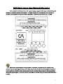
Controlled Access Inc. – BR5500-S Service and Installation Manual
BR5500-S Waist High Turnstile
Service & Installation Manual
Note: Successful turnstile installation depends on reading this manual.
Important Note: Please keep this service manual after installation. If an installation is done by a
construction company or outside installer, please pass this book along to the end user. This
book is required for maintenance, troubleshooting, and repairs.
Security Begins With Controlled Access
1636 W. 130th Street, Brunswick, OH 44212
Toll Free Phone: (800) 942-0829 | Fax: (800) 942-0828 / Phone: (330) 273-6185 | Fax: (330) 273-4468
Web: http://www.controlledaccess.com | E-mail: [email protected]
1
Important Electrical Information
Installation of the control head mechanism into the turnstile requires a grounding-type
outlet receptacle installed inside of the frame or cabinet through the provided conduit
access points.
To reduce the risk of electric shock, this equipment has a grounding type plug that has a
third (grounding) pin. This plug will only fit into a grounding type outlet. If the plug does
not fit into the outlet, contact a qualified electrician to install the proper outlet. Do not
change this plug in any way.
Additionally, the MS2-H50 power supply from this appliance must be grounded to the
frame of the turnstile. Utilize the green colored grounding screw threaded into the
grounding tab located near the power supply along with the provided grounding wire from
the power supply to ensure the equipment is proper grounded.
Security Begins With Controlled Access
1636 W. 130th Street, Brunswick, OH 44212
Toll Free Phone: (800) 942-0829 | Fax: (800) 942-0828 / Phone: (330) 273-6185 | Fax: (330) 273-4468
Web: http://www.controlledaccess.com | E-mail: [email protected]
2
The Brute Series Waist-High
BR5500-S
™
Bolt Down • Interior and Exterior Application
The Brute™ Series units operate
reliably with high traffic volumes
where cost is an important
consideration. Heavy 7-gauge
carbon steel cabinets can be
interfaced with optional LCD
counters, card readers, push
button and wireless remotes.
Portable units (BR5000-P) are also
available. Standard colors are black,
gray, and almond but custom colors
are available and can be quoted
upon request. As always, we offer
an ADA compliant handicapped
gate with this series. (BR5000-ADA).
Available in:
Black
Gray
Almond
Standard colors are
black, gray and almond,
but custom colors are
available and can be
quoted upon request.
We’re the #1 Choice of Top Architects,
Security Pros and Engineers
For two decades, Controlled Access has been the globally trusted name in
pedestrian control equipment. Made in Ohio and shipped worldwide, we are
the first choice of leading architects, facility managers, security consultants
and engineers. Whether your project requires high security full-height
turnstiles, waist-high units, or matching ADA accessible gates, Controlled Access
is the secure choice. And, we’re experienced in access control systems, from
card readers to biometric scanning, to give you the power to control access.
CONTROLLED ACCESS, INC.
Built in the USA
The Leader in Pedestrian Access Control
1636 West 130th Street | Brunswick, Ohio 44212 | Ph: 330.273.6185 | Fax: 330.273.4468 | Toll-Free Ph: 800.942.0829 | Toll-Free Fax: 800.942.0828
E-mail: [email protected] | www.controlledaccess.com
0214
The Brute Series Waist-High
BR5500-S
™
Bolt Down • Interior and Exterior Application
Applications:
This series is made for years of reliable service in high traffic / volume environments
like stadiums, convention centers, amusement parks, landmarks and military bases.
Product Features:
Materials and Finishes:
• Lid: Our signature 304 stainless steel /
No. 4 satin finish
• Cabinet: Your choice of designer powder coat
colors to match any décor. Black is standard.
Design & Construction:
• Designed for secure and reliable operation
with aesthetics in mind
• Cabinet is constructed with rigid (7 gauge)
carbon steel
• Cover is constructed with (14 gauge) 304
stainless steel, No. 4 satin finish
• Arm assembly constructed with 1 5/16”
(33mm) diameter, (12 gauge) stainless steel
• Hub 4 1/2” (114mm) o.d. also made from
stainless
Measurements:
•
•
•
•
Height: 37” (939.8mm)
Width: 20.125” (511.1mm)
Depth: 8” (203.2mm)
Arm Length: 14.500” (368.3mm)
Operation:
6500 Series Control Head, featuring:
• Auto-indexing (self-centering) with adjustable
hydraulic shock suppression
• Hardened tool steel locking bars, cam and
roller assemblies
• Permanently lubricated bearings
• Your choice of manual or electronic control
on both directions
• Nearly universal integration to any number
of access control systems
• Your choice on each electronic direction
of locking or unlocking on power failure
Options:
• Bidirectional key overrides
• Daylight visible indicator lights
• 8 digit key resettable LCD counter with
seven year lithium battery
• Rubber arm covers
• Additional options available on request
Warranty:
Units are warranted against defects in materials
and workmanship for a period of one year from
date of delivery. See warranty information
for specific details.
Dimensions are approximate.
Electrical Specifications:
Input Voltage: 100-240 VAC
Input Current: 1.3 - .55 A
Frequency: 50/60 Hz
Storage Temperature: -4 to 158˚F
Operating Temperature: 32 to 122˚F
Operating Voltage: 24VDC
Operating Current: 1.2 A (typical)
Standards and Codes:
Have an older style Brute cabinet
that you need to match?
Just ask!
Austenitic stainless steel:
ASTM A240, A249, A276
Hot rolled steel:
AISI C-1020, AISI C-1018
Hot dipped galvanizing:
ASTM A-143, ASTM A-153-80
Stainless steel fasteners:
ASTM A-320
American Welding Society (AWS)
Standard D 1.1
Our matching ADA gate
(BR5000-ADA) is available for the Brute Series.
The 6500 series control head is
certified to conform to UL Standard
325 & UL Subject 2593
Controlled Access, Inc. is
a registered ISO 9001:2008
company
CONTROLLED ACCESS, INC.
The Leader in Pedestrian Access Control
1636 West 130th Street | Brunswick, Ohio 44212 | Ph: 330.273.6185 | Fax: 330.273.4468 | Toll-Free Ph: 800.942.0829 | Toll-Free Fax: 800.942.0828
E-mail: [email protected] | www.controlledaccess.com
0214
Controlled Access Inc. – BR5500-S Service and Installation Manual
Pre-Installation Planning
Although the BR5500-S is simple to install, there are a few things to be familiar with in order to simplify
the process.
The cabinet has conduit access built into the floor plate and bottom side of the head plate. Additionally,
although the cabinet itself can be used as a template for concrete anchors, the diagram below indicates
the location of the anchor holes and conduit access.
If your BR5500-S is set up for electronic control, a grounded outlet receptacle will need to be
installed inside of the cabinet.
Access control integration is built into the controls. To activate and unlock a direction, you must provide
a normally open dry momentary contact of 1 second or less. If the output timer from your access control
system is too long, the unit may allow more than one person through the unit.
If you have purchased a digital counter for your BR5500-S, there are multiple ways it can be wired,
depending on the operation of the rest of the controls. Manual turnstiles utilize a limit switch and top
cam to initiate a count; where as electronic turnstiles utilize the 789 control board to count upon
activation.
Security Begins With Controlled Access
1636 W. 130th Street, Brunswick, OH 44212
Toll Free Phone: (800) 942-0829 | Fax: (800) 942-0828 / Phone: (330) 273-6185 | Fax: (330) 273-4468
Web: http://www.controlledaccess.com | E-mail: [email protected]
4
Controlled Access Inc. – BR5500-S Service and Installation Manual
Concrete Anchor Installation
Security Begins With Controlled Access
1636 W. 130th Street, Brunswick, OH 44212
Toll Free Phone: (800) 942-0829 | Fax: (800) 942-0828 / Phone: (330) 273-6185 | Fax: (330) 273-4468
Web: http://www.controlledaccess.com | E-mail: [email protected]
5
Controlled Access Inc. – BR5500-S Service and Installation Manual
BR5500-S Installation
1. Floor should be level within 1/16”. If not, you must shim underneath the cabinet. Installing
turnstile to uneven surface can cause operational issues.
2. Place template or cabinet in its installation location and use a center punch to mark the 4
anchor holes.
3. Drill 3/8” holes into concrete 4” deep and remove all concrete dust from the holes.
4. Place the turnstile back in its correct position and install concrete anchors as indicated on page
6.
5. Wire turnstile or handicapped gate with 1 10 volt minimum 2 amp GFI circuit to terminals
provided. These must be grounded. Most card readers provide normally open contacts which
are activated upon acceptance of card presented. These contacts are to be wired to terminals.
See electrical drawings supplied.
6. Bolt the arm assembly to the arm adaptor with the provided 5/16 carriage bolts.
7. Please give owner all maintenance and parts manuals supplied with this equipment.
Security Begins With Controlled Access
1636 W. 130th Street, Brunswick, OH 44212
Toll Free Phone: (800) 942-0829 | Fax: (800) 942-0828 / Phone: (330) 273-6185 | Fax: (330) 273-4468
Web: http://www.controlledaccess.com | E-mail: [email protected]
6
7
8
9
6500 Series Control Head Configuration Information
The 6500 series can be configured in a number of different ways. All turnstiles operating with the 6500
series control head self center and hydraulically shock to the home position to prevent damage or injury.
Manual both ways: Turnstile rotates freely in both directions. This unsecure configuration is used as a means
to direct traffic through one area. Full height turnstiles can be purchased with a lockout bar which would allow
end user to lock the turnstile with a standard pad lock.
Manual one way: Turnstile rotates in one direction but not the other. This configuration is great for an exit
way.
Electronic one way with free exit: Turnstile rotates freely in one direction and requires access credentials for
the other. This configuration is suitable for secure entry and unsecure exit.
Electronic one way with no exit: Turnstile requires access credentials for one direction and allows no passage
in the other. This configuration is suitable for a secured entryway with an alternate means of exit.
Electronic two way: Turnstile requires access credentials for both directions. This configuration is perfect for
locations requiring secured entry and exit passage.
Fail lock: Upon power failure, turnstile will remain locked in one or both directions. This is convertible to fail
open by ordering an alternate linkage. This can also be known as fail secure.
Fail open: Upon power failure, turnstile will remain unlocked in one or both directions. This is convertible to
fail lock by ordering an alternate linkage. This can also be known as fail safe.
Key override: This option is for a location that the security requirements may change. The key override option
is not intended for everyday use
10
11
12
13
14
15
6500 Series Control Head Wiring Legend
Since each control head comes pre-wired, only access control and fire alarm should need to be connected to the
board. If you are unable to fit wires for access control on the 24VDC+ input on the board, the voltage can be
picked up directly from the power supply or from the relay commons (C3 & C4) on the board (C4 may not have
voltage depending on options purchased. There will be a red jumper to C4 if there is). You may also run a jumper
from 24VDC+ to any unused input to give additional contacts if needed.
Note: Directional status outputs are unaffected by optional key overrides as the override occurs
outside of the logic controller.
Security Begins With Controlled Access
1636 W. 130th Street, Brunswick, OH 44212
Toll Free Phone: (800) 942-0829 | Fax: (800) 942-0828 / Phone: (330) 273-6185 | Fax: (330) 273-4468
Web: http://www.controlledaccess.com | E-mail: [email protected]
17
18
19
•
•
DM9: Direction 1 Count: Displays how many valid rotations were made in direction 1. This has a max
value of 60,000 and will reset to 0 once that number is reached. This will not count fire alarm, hold open
or key override rotations. This count is for maintainence and repair logging purposes.
DM10: Direction 2 Count: Displays how many valid rotations were made in direction 2. This has a max
value of 60,000 and will reset to 0 once that number is reached. This will not count fire alarm, hold open
or key override rotations. This count is for maintainence and repair logging purposes.
Additionally, scrolling downward past DM0 will allow you access to DM1999, which resets all settings to factory
defaults (except for solenoid fail status settings). Choose any value greater than 0 to perform the factory reset.
20
21
22
23
6500 Series Control Head Troubleshooting
Symptom
Turnstile does not unlock.
Cause
Power supply is not receiving
input voltage.
Loose wiring from power supply
to logic controller.
Power supply is not producing
voltage.
Logic controller program is not
running. This can be determined
by the color of the lettering on
the logic controller display
screen. If it is red, it is not
running.
Access control device
malfunction.
More than one person can get
through turnstile.
Control head requiring
maintenance.
Access control device output set
too long.
Loose wiring to the logic
controller from limit switches.
Limit switches are broken.
Limit switches are missing the
triangular top cam.
Unable to hold direction open to
allow multiple people to pass
through the turnstile.
One-shot timers are enabled.
Solution
Verify outlet receptacle installed
in mainframe is operating
correctly and that the power
supply is plugged in.
Refer to pages 15-17 for
wiring information.
Check output voltage from
power supply. It should be
24VDC.
Refer to the “Overview of the
Access Window“ section on
page 18 and “run” the program.
Disconnect access control from
circuit board. Momentarily jump
directional inputs. If the turnstile
works properly, contact
manufacturer of access control
device.
Refer to page 23.
This can be avoided by enabling
the one-shot timers built into the
logic controller program. If this is
undesirable, ensure the output
from the access control system is
1 second or less.
Refer to pages 15-17 for
wiring information.
Inspect limit switches for
breakage, replace as needed.
Adjust the top cam to the proper
height and or tweak the triggers
on the limit switch. Refer to
page 22 for information.
Disable the one shot timer
settings on the logic controller.
Be sure that your access control
output is one second or less
during regular secure operation
or extra people may be able to
pass through.
24
Turnstile only rotates 30
degrees.
Limit switches wired incorrectly.
Top cam is misaligned.
Unit remains unlocked until
access control is presented.
Turnstile is slamming into the
closed position.
Turnstile is not centering
properly.
Fail open / fail lock configuration
is wrong.
Shock either needs adjusted or
replaced.
Shock needs adjusted.
Turnstile seems to be binding
mechanically.
Binding in control head.
Rotor is not plumb / turnstile
body is not level.
Turnstile rotating the wrong
direction.
Control head requires
maintenance.
Improperly filled out direction
sheet.
Directional inputs wired
incorrectly.
Turnstile fails lock when needed
to fail open or vice versa.
Other problems.
Improperly filled out direction
sheet.
Refer to pages 15-17 for wiring
information and page 22 for
limit switch placement.
The top cam should have one
point facing the control board. If
this is not the case, readjust the
top cam. Refer to page 22 for
top cam information.
Change fail open / fail lock mode
on each direction as appropriate.
Refer to page 14 for more
information.
Refer to page 14 for more
information.
See next troubleshooting hint.
Level out the turnstile
with shims
Refer to page 23 for
more information.
In some cases, the control head
can be reconfigured in the field
to operate as needed. Refer to
pages 8-13 for information
about how the control head
operates. If needed, control
heads can be returned to the
factory for reconfiguration for a
fee of labor plus parts (if
required). Please contact us
before returning a control head
in this instance.
Refer to wiring legend for
direction port explanations
on page 17
Refer to page 13 for more
information. Additional parts will
be required to convert
operation. The control head can
be returned for reconfiguration
for a fee of labor plus parts (if
required). Please contact us
before returning a control head
in this instance.
Please contact us for any other
issues.
25
26
27
■ Precautions for UL Standards
96M1274
The MS2 Series meets the following UL standards and has obtained UL and C-UL certification.
• Applicable standard UL508
Industrial Control Equipment
UL60950-1 Information Technology Equipment - Safety
CAN/CSA C22.2 No. 14-M95
Industrial Control Equipment
CAN/CSA C22.2 No. 60950-1-03
Information Technology Equipment - Safety
• UL File No.
E195940, E242533
• UL category
NMTR, NMTR7 / QQGQ2, QQGQ8
<Precautions>
• Use wires that meet the following conditions for the terminal block.
(tightening torque : 1.2 N·m)
Wire range
AWG#14-22
Wire Material
Copper wire only
Wire type
Stranded wire only
Temperature rating
60ºC/75ºC
• The MS2 Series is designed as a Class I Equipment. Be sure to connect the protective earthing
terminal on the terminal block to the protective earthing conductor in the building installation.
• The MS2 Series is an open-type device. Be sure to install it in an appropriate enclosure rated as
IP54 or better.
• Use the MS2 Series according to the derating conditions and the installation conditions described in
this manual.
• The MS2 Series does not include a disconnecting device. Be sure to install a disconnecting device
such as a circuit breaker in the building installation wiring.
• The output of the MS2-H50 is regarded as Class 2 output specified in NEPA70 (NEC: National
Electrical Code) in the U.S.A. (UL Category: EPBU2/EPBU8)
Compact Switching Power Supply
MS2 Series
Instruction Manual
Part Names and Functions
.8.8.8
Digital display window
Displays the current values of output current/voltage and other items.
Display mode selection (MODE)
Switches the display mode.
Output voltage adjustment trimmer (V.ADJ)
Adjusts the output voltage within the range of ±5%.
Installation Conditions
■ Installation environment
•
•
•
•
•
•
DC output terminal (+, –) *
A load is connected here. (24 VDC)
Protective earthing terminal ( )
Connect to the protective earthing conductor in the building
installation.
■ When installing this unit in a control console
• The ambient temperature for this unit should not exceed the upper temperature limit (refer to the
derating characteristic). When the upper temperature limit may be exceeded, install a cooling fan or
cooler so that the ambient temperature is below the upper temperature limit.
• Leave a sufficient ventilation space around this unit for head dissipation.
• Do not install this unit just above a device with high head generation (transformer, inverter, servo
amplifier, etc.).
AC input terminal (N, L)
An input cable is connected here. (100 to 240 VAC)
*Only the MS-H300 has DC output of 4-terminal.
Safety Precautions
Danger
Warning
Caution
Installation this unit indoors.
Do not install this unit in locations exposed to direct sunlight.
Do not install this unit in locations in which there is corrosive gas or flammable gas.
Do not install this unit in locations exposed to a lot of dust, soot, or stem.
Do not install this unit in locations in which water, oil, or chemicals may splash onto the unit.
When installing this unit in a location subject to vibration or impact, consider the vibration proof
mounting.
Installation
• Do not perform any electrical wiring while electric current is applied. Failure
to follow this may result in an electric shock or fire.
• Be sure to connect the grounding cable. Failure to follow this may result
in an electric shock or fire.
• Do not touch this unit within 1 minute after AC input is turned off. Failure
to follow this may result in an electric shock.
• Do not modify or repair this unit. Failure to follow this may result in an
electric shock, accident, or product failure.
• Do not touch any terminal of this unit while electric current is applied.
Use the unit with the terminal cover installed to avoid an electric shock.
■ Space around the unit
The MS2 Series uses natural air-cooling. To ensure sufficient convection of air to dissipate heat, provide
enough space between the MS2 Series and the control panel or other nearby devices as shown below.
MS2-H50/H75/H100/H150
MS2-H300
20mm min.
20mm min.
• When this unit is used in a system that may cause a serious accident or
damage if the unit fails, be sure to install a safety device.
• Pay attention to prevent foreign matter such as metal particles, dust,
paper or wood chips from entering the inside of this unit. Failure to
follow this may result in a fire or product failure.
• Do not touch any metallic part while electric current is applied or
immediately after input is shut off. Failure to follow this may result in a
burn due to a high temperature.
• If a failure or abnormality occurs while this unit is in use, immediately
such off AC input and stop operation of this unit . Failure to follow this
may result in a fire or accident.
20mm min.
60mm min.
30mm
min.
30mm min.
30mm min.
20mm min.
■ Installation orientation
Install this unit with the base A down as shown below. Do not install the unit in any other orientation.
• Check that the AC input rated voltage of this unit is equal to the voltage
of the AC power supply.
• Do not connect the AC power supply to the DC output terminals.
• Do not disturb the convection of air near the vent of the casing.
■ Precautions for CE Markings
■ Mounting bracket (optional)
KEYENCE has evaluated the conformity of the MS2 Series with the requirements of the EMC
Directives and Low-voltage Directives under the following condition, and confirmed that the MS2
Series meets these requirements. For the Low-voltage Directives, the MS2 Series has obtained
certification from TUV Rheinland for the following standards.
<Precautions>
● EMC Directives (89/336/EEC)
• Applicable standard (EMI)
EN55011, Group 1, Class A
• Applicable standard (EMS)
EN61000-6-2
● Low-voltage Directives (73/23/EEC)
• Applicable standard
EN60950-1
EN50178
• Overvoltage category
II
• Pollution degree
2
Make sure that the tightening torque for the mounting screw holes of this unit is 0.5 N•m or less.
Wiring
Terminals
Screw size
Tightening torque
M4
1.2 N•m
Crimp termianls
M4 size
8.0 mm max.
• The MS2 Series is designed as a Class I Equipment. Be sure to connect the protective earthing
terminal on the terminal block to the protective earthing conductor in the building installation.
• The MS2 Series is an open-type device. Be sure to install it in an appropriate enclosure rated as
IP54 or better.
• Use the MS2 Series according to the derating conditions and the installation conditions described in
this manual.
• The MS2 Series does not include a disconnecting device. Be sure to install a disconnecting device
such as a circuit breaker in the building installation wiring.
M4 size
8.0 mm max.
Cables
Select cables with a wire diameter suited to the output rated current.
1
Method of Operation
Dimensions
The display mode changes each time when the MODE switch is pressed.
MS2-H50/H75/H100
MS2-H300
(12)
.8.0.7
Output current display
G
A
Displays the load factor down to 1%.
When the load factor is over 100% , displays "FFP".
.3.5.P
°
35.9
P=10
46.5
16.8
C
D
Displays the maximum value of the output current down to
0.1 A. The current and "PH" are displayed alternately.
.8.1.3
15
F
3
70.5
140
21.5
10
27.5
H
16.5
96
78
2
B
I
▼
J
.2.4.0
Output voltage display
124
35.9
10
▼
Peak current display
131.5
Displays the output current down to 0.1 A.
▼
Load factor display
(10)
E
120
Displays the output voltage down to 0.1 V.
Screw hole for mounting
Nominal diameter 3 Tapping depth 4 max.
Model
A
99.5
MS2-H50
MS2-H75/H100 114.5
• The MS2 Series is set to the output current display mode before shipment. It retains the display
mode that was used before the power was turned off.
• The maximum value for the peak current display mode is cleared when the power is turned off and
the display mode is changed.
• When the switch is held down for 3 seconds or more, the current mode is locked and cannot be
changed. To unlock the mode, hold down the switch again for 3 seconds or more.
B
40
52
C
D
14.7 14.6
15.1 17.1
E
97
110
F
65
78
G
33.4
41
H
40
52
I
J
5
30
4.75 42.5
Screw hole for mounting
4-M3 Screw insertion depth 5 max.
MS2-H150
(12)
When front mounted
120
43.3
35.9
122.5
A
10
Dimensions
14.3
F
E
60
3.9 A/1.8 A max.
t=2
D
C
28
4-φ5
B
15.5
Mounting bracket OP-51624
OP-42174
OP-51627
Matching model MS2-H50 MS2-H75/H100 MS2-H150
170
A
123.5
159.5
122
B
99
112
59
C
45
54
40
D
20
30
12.5
E
8
12.5
15
F
15
Two holes only for OP-51624.
28
18 A/36 A max.
24 VDC
± 5%(with V.ADJ)
4.5 A
6.5 A
12.5 A
180mVp-p max.
0.4 % max.
1.5 % max.
0.02 %/ºC max.
500 ms max. (at Surrounding Air Temperature of 0 to 55°C under ated
r
I/O conditions)
20 ms min. (at Surrounding Air Temperature of 25°C under ated
r
I/O conditions)
Protection
16.5
85.5
2.5
0.4 mA/0.75 mA max. (with 100% load)
Screw hole for mounting
4-M3 Screw insertion depth 5 max.
3.2 A
When bottom mounted
When side mounted
Activates when the current reaches 125% or more of the rated output current.
Constant current voltage limiting. Automatic reset
4.0 A min.
5.3 A min.
7.9 A min.
15.6 A min
Activates when the voltage reaches 26.4 V or more. Voltage turn-off.
Operation resumes when the input power is turned on again.
2.7 A min.
Overvoltage protection ∗ 2
A
A
3-digit, 7-segment LED (Character height: 10 mm)
Approx. 10 years (at 20°C)
0.1 A/0.1 V/1%
t=2
–10 to 55ºC, No condensation (See "Output Derating Characteristics".)
12.5
25 to 85%, No condensation
5
B
Peak acceleration: 300 m/s2, in X, Y, and Z directions,
2 times respectively
Shock
E
B
100 MΩ min. (with 500 VDC megohmmeter) (across input and output terminals)
(across input terminals and PE terminal) (across output terminals and PE terminal)
EMC standard
D
C
F
Mounting bracket OP-51626
OP-51623
Matching model MS2-H50 MS2-H75/H100 MS2-H150
120.5
153.5
157
A
54
60
B
45
75
75
C
65
50
50
D
40
12.5
12.5
E
12.5
16
20.5
F
14.5
12.5
12.5
G
8
15
15
H
4-φ5
Mounting bracket OP-51625
OP-42175
OP-51628
Matching model MS2-H50 MS2-H75/H100 MS2-H150
107.5
122.5
A
132.5
150
135
160
B
C
45
54
55
20
30
40
D
125
140
150
E
UL : UL508, UL60950-1
C-UL : CSA C22.2 No.14-M95, CSA C22.2 No.60950-1-03
EN : EN60950-1, EN50178
IEC : IEC60950-1
Safety standard
E
D C
In X, Y, and Z directions, 2 hours respectively under the following conditions
10 to 57 Hz, 0.3 mm double-amplitude, 57 to 500 Hz, 19.6 m/s2 (2G), 5.5-minute cycle
Insulation resistance
Two holes only for OP-51626.
The side mounting bracket can be attached to either sides.
FCC Part15B ClassA, EN55011 ClassA, EN61000-6-2
EN61000-3-2 ∗ 3
Limits for harmonic current emissions
Parallel operation
Serial operation
Cooling method
Weight
Possible (OP-42207 is required.) ∗ 4
Possible (External diode is required.) ∗ 4
Natural air-cooling
Approx. 490g
Approx. 700g
Approx. 470g
Approx. 27 0g
WARRANTIES (MUST ACCOMPANY THE PRODUCTS): KEYENCE, at its sole option,
will refund, repair or replace at no charge any defective Products within 1 year from the
date of shipment. Unless stated otherwise herein, the Products should not be used
internally in humans, for human transportation, as safety devices or fail-safe systems.
EXCEPT FOR THE FOREGOING, ALL EXPRESS, IMPLIED AND STATUTORY
WARRANTIES, INCLUDING WARRANTIES OF MERCHANTABILITY, FITNESS FOR A
PARTICULAR PURPOSE AND NONINFRINGEMENT OF PROPRIETARY RIGHTS, ARE
EXPRESSLY DISCLAIMED. KEYENCE SHALL NOT BE LIABLE FOR ANY DIRECT,
INDIRECT, INCIDENTAL, CONSEQUENTIAL OR OTHER DAMAGES, EVEN IF
DAMAGES RESULT FROM THE USE OF THE PRODUCTS IN ACCORDANCE WITH
ANY SUGGESTIONS OR INFORMATION PROVIDED BY KEYENCE. In some
jurisdictions, some of the foregoing warranty disclaimers or damage limitations may not
apply.
Approx. 1540g
∗1 For conforming to safety standards shown above, rated input voltage is 100 to 240 VAC 50/60 Hz.
∗2 To reset the unit, turn off the input power once, wait for 1 minute or more, and then turn on the input power again.
∗3 For MS2-H100, it is applied only when the load ratio is 70% or lower.
∗4 The Applicable standards do not apply for parallel and serial operations.
Output Derating Characteristics
100
90
80
70
60
50
40
30
20
10
0
-10
MS2-H75
Load factor (%)
MS2-H50/H150
Load factor (%)
H
G
t=2
3.0 kVAC 50/60 Hz 1 min (across input and output terminals),
2.0 kVAC 50/60 Hz 1min (across input terminals and PE terminal)
500 VAC 50/60 Hz 1 min (across output terminals and PE terminal)
Withstand voltage
0
10
20
30
40
50
60
70
100
90
80
70
60
50
40
30
20
10
0
-10
Surrounding air temperature (°C)
0
0
20
30
40
50
60
KEYENCE CORPORATION
70
1-3-14, Higashi-Nakajima, Higashi-Yodogawa-ku,
Osaka, 533-8555, Japan
Phone: 81-6-6379-2211 Fax: 81-6-6379-2131
MS2-H300
Load factor (%)
100
90
80
70
60
50
40
30
20
10
0
-10
10
Surrounding air temperature (°C)
MS2-H100
Load factor (%)
7
–20 to 70° C, N ocondensation
Vibration
Applicable standard
59
MS2-H300
25 A/50 A max. (with 100% load, at 25°C cold start)
2.1 A(Class2)
Display method
Memory backup time
Display resolution
Surrounding Air Temperature
(for operation)
Relative humidity
Surrounding Air Temperature
(for storage)
Other
MS2-H75
MS2-H100
MS2-H150
100 to 240 VAC ( 85 to 264 VAC, 110 to 370 VDC)
50/60 Hz ( 47 to 63 Hz, DC )
1.9 A/0.9 A max.
2.1 A/1.3A max.
2.2 A/1.1 A max.
82%/85% typ. (with 100% load)
1.3 A/0.7 A max.
Rated output voltage
Adjustable voltage range
Rated output current
Ripple/noise voltage
Input fluctuation
Load fluctuation
Temperature fluctuation
Starting time
Output holding time
Overcurrent protection
Environment
MS2-H50
Rush current (100/200 VAC)
Display
Output conditons
Input conditons
16.1
Model
Rated Input voltage ∗ 1
Rated Frequency ∗ 1
Input current (100/200 VAC)
Efficiency (100/200 VAC)
Leakage current
(100/200 VAC)
10
20
30
40
50
60
Surrounding air temperature (°C)
70
100
90
80
70
60
50
40
30
20
10
0
-10
AFFILIATED COMPANIES
0
10
20
30
40
50
60
70
Surrounding air temperature (°C)
* The characteristic data shown above are obtained when this unit is installed as described in this
Manual.
* The surrounding air temperature is the temperature 50 mm below the bottom of the MS2 Series unit.
KEYENCE CORPORATION OF
AMERICA
Phone: 201-930-0100 Fax: 201-930-0099
KEYENCE (MALAYSIA) SDN BHD
Phone: 03-2092-2211 Fax: 03-2092-2131
KEYENCE DEUTSCHLAND GmbH
Phone: 06102-36 89-0 Fax: 06102-36 89-100
KEYENCE (THAILAND) CO., LTD.
Phone: 02-369-2777 Fax: 02-369-2775
KEYENCE (UK) LIMITED
Phone: 01908-696900 Fax: 01908-696777
KEYENCE TAIWAN CO., LTD.
Phone: 02-2718-8700 Fax: 02-2718-8711
KEYENCE FRANCE S.A.
Phone: 01 56 37 78 00 Fax: 01 56 37 78 01
KEYENCE (HONG KONG) CO.,LTD.
Phone: 3104-1010 Fax: 3104-1080
KEYENCE ITALIA S.p.A.
Phone: 02-6688220 Fax: 02-66825099
KEYENCE INTERNATIONAL
TRADING (SHANGHAI) CO.,LTD.
Phone: 021-68757500 Fax: 021-68757550
KEYENCE SINGAPORE PTE LTD.
Phone: 6392-1011 Fax: 6392-5055
KOREA KEYENCE CO., LTD.
Phone: 02-563-1270 Fax: 02-563-1271
Specifications are subject to change without notice.
B0124
© KEYENCE CORPORATION, 2004
0086 96M1274 Printed in Japan
2
PLC Specifications
Performance specifications
General specifications
Model
Rated voltage
Base unit
100 to 240 VAC (±10%)
24 VDC (+10%, -20%)
Instruction types
Others Expansion units
KV-10AT(P)/DT(P): 80(85) mA max.
KV-16AT(P)/DT(P): 90(100) mA max.
KV-24AT(P)/DT(P): 100(105) mA max.
KV-40AT(P)/DT(P): 120(130) mA max.
KV-E16X: 35 mA max.
KV-E16T(P): 60(70) mA max.
KV-E16R: 110 mA max.
KV-E4XT(P): 30 mA max.
Insulation
resistance
Environmental
restrictions
Internal utility relay
Special utility relay
Data memory (16 bits)
Temporary data
memory (16 bits)
2,560 points: 1000 to 1915 and 3000 to 17915
High-speed counter
comparator
160 points: 2000 to 2915
2,000 words: DM 0000 to DM1999
32 words: TM00 to TM31
250 in all:
0.1-s timer: TMR (0 to 6553.5 s),
0.01-s timer: TMH (0 to 655.35 s),
0.001-s timer: TMS (0 to 65.535 s),
UP counter: C,
Up/down counter: UDC
2 trimmers (set in access window)
2 counters of 30 kHz, 2-phase high-speed counter
(0 to 65535 count) *1
4 comparators (2 for each high-speed counter)
Direct output allowed
Positioning
control function
Memory switch
Program memory
Data memory,
counter,
internal utility
relay
Independent 1 axis, 50 kHz max.
16
Flash ROM, rewritable 100,000 times or more
Data retained for 2 months min.
with electrical double-layer capacitor (at 25°C),
Data can be backed up with Flash ROM in all models.
(Retention devices are set
by MEMSW instruction.)
Self-diagnosis
Number of contact
comments
No excessive dust or corrosive gases
KV-10AR: Approx. 250 g,
KV-16AR: Approx. 300 g,
KV-24AR: Approx. 350 g,
KV-40AR: Approx. 450 g,
KV-10DR: Approx. 150 g,
KV-16DR: Approx. 190 g,
KV-24DR: Approx. 240 g,
KV-40DR: Approx. 330 g,
Weight
10 to 152 points
(when expansion units are connected)
-20 to +70°C
10 to 55 Hz, 1.5 mm max. double amplitude in X, Y and Z directions,
2 hours respectively (1 G max. when attached to DIN rail)
50 MΩ min. (Between power terminal and I/O terminals,
and between external terminals and housing, measured
with 500 VDC megohmmeter)
Vibration
Number of I/O points
(including 10 to 40 I/O
points of basic unit)
High-speed counter
150 m/s 2 (15 G), working time: 11 ms,
in X, Y and Z directions, 2 times respectively
Shock
8 (7 for KV-40xx)
Digital trimmer
1,500 Vp-p min., pulse width: 1 μs, 50 ns (by noise simulator)
Conforming to EN standard (EN61000-4-2/-3/-4/-6)
Noise immunity
2,000 steps (KV-10xx, KV-16xx)
4,000 steps (KV-24xx, KV-40xx)
Maximum number of
expansion units
0 to 50°C, 0 to 45°C (KV-P3E)
35 to 85%
1,500 VAC for 1 minute
(Between power terminal and I/O terminals,
and between external terminals and housing)
Withstand voltage
140 μs min.
Basic instruction: 0.7 μs min.,
Application instruction: 6.4 μs. min.
Timer/counter
KV-D30 Operator interface panel: 60 mA max.
KV-P3E Handheld programmer: 65 mA max.
Ambient temperature
Relative humidity
Ambient storage
temperature
Basic instruction: 28, Application instruction: 22,
Arithmetic instruction: 26, Interrupt instruction: 4
Program capacity
2 ms max.
KV-E8X: 25 mA max.
KV-E8T(P): 40 mA max.
KV-E8R: 70 mA max.
KV-E4XR: 45 mA max.
Refresh method
Ladder diagram and expanded ladder diagram
Instruction
processing time
40 ms max.
KV-10AR/DR: 100 mA max.
KV-16AR/DR: 120 mA max.
KV-24AR/DR: 140 mA max.
KV-40AR/DR: 180 mA max.
Stored program method
Minimum scan time
KV-10AT(P)/AR: 0.4 A
KV-16AT(P)/AR: 0.6 A
KV-24AT(P)/AR: 0.6 A
KV-40AT(P)/AR: 0.7 A
Allowable
instantaneous
interruption time
Internal current
consumption
(converted into
24 VDC value)
Arithmetic operation
control method
I/O control method
Programming
language
Memory backup
(Including the internal
current consumption
and current consumption
of expansion units.)
DC type
KV-10DT(P)/DR KV-16DT(P)/DR
KV-24DT(P)/DR KV-40DT(P)/DR
KV-10AT(P)/AR: 0.4 A
KV-16AT(P)/AR: 0.5 A
KV-24AT(P)/AR: 0.6 A
KV-40AT(P)/AR: 0.7 A
60%
24 VDC (±10%)
AC current
consumption
AC power factor
Output voltage
Output capacity
AC type
KV-10AT(P)/AR KV-16AT(P)/AR
KV-24AT(P)/AR KV-40AT(P)/AR
CPU and RAM errors
1,000 max. contact comments can be saved.
*1. 24-bit setting is available.
KV-10AT(P): Approx. 240 g,
KV-16AT(P): Approx. 280 g,
KV-24AT(P): Approx. 330 g,
KV-40AT(P): Approx. 410 g,
KV-10DT(P): Approx. 140 g,
KV-16DT(P): Approx. 180 g,
KV-24DT(P): Approx. 210 g,
KV-40DT(P): Approx. 280 g
Input/output circuit of base unit
Input 000 to 007
Internal
circuit
Photocoupler
insulation
510 Ω
C
KV-xx DT/AT (NPN)
Insulated
power supply
4.3 kΩ
KV-xx DTP/ATP (PNP)
1.6 kΩ 1/2 W
R50x
500 or later
C
Insulated
power supply
KV-xx DR/AR
C
500 or later
R50x
1.6 kΩ 1/2 W
Internal circuit
C
008 or later
Internal circuit
24 V/5 V
switching
circuit
Input 008 or later
Internal circuit
000 to 007
Photocoupler
insulation
Internal circuit
4.3 kΩ
500 or later
C
Input specifications of base unit
Model
No. of inputs
Input common
KV-10xx KV-16xx KV-24xx KV-40xx
6
24
10
16
COM is connected internally.
Maximum input
rating
Input voltage * 1
24 VDC, 5.3 mA/5 VDC, 1.0 mA
Output specifications of basic unit
Model
No. of outputs
Output common
Output type
26.4 VDC
Rated load
10 ms (Typical)
10 µs when HSP instruction is used
Variable in 7 steps from 10 µs to
Input time constant
10 ms while special utility relay 2813
is ON (Set by DM1940)
Interrupt input
response
High-speed counter
input response
KV-10xT(P) KV-16xT(P) KV-24xT(P) KV-40xT(P) KV-10xR KV-16xR KV-24xR KV-40xR
4
6
8
16
4
6
8
16
1 common
Each common terminal is independent.
Transistor output (NPN or PNP)
Relay output
30 VDC
250 VAC/30 VDC
0.3 A (503 and other)
2 A (Inductive load)
0.1 A (500 to 502)
4 A (Resistive load)
0.2 A (500 to 502)
1 A (Other)
Peak load current
5A
Electrical service life:
100,000 times or more (20 times/min)
Mechanical service life:
20-million times or more
Relay service life
10 µs (Typical)
Relay replacement
Output frequency
30 kHz (24V±10%)
Built-in serial
resistance
*1. Inputs 000 to 007 can be changed to 5 V input.
Not allowed
50 kHz (500 to 502)
1.6 kΩ 1/2W (R500 to R502)
Input/output specifications of expansion unit
Input/output
External
connection method
Model
Number of inputs
Input common
Maximum input
rating
Input voltage
Minimum ON voltage
Input
KV-E8X
KV-E16X
8
16
4 points/common
(Changed in two steps by
special utility relays 2609
to 2612)
KV-E8T(P)
KV-E16T(P)
KV-E16R
KV-E4XT(P)/R
4
4 points/common
26.4 VDC
26.4 VDC
24 VDC, 5.3 mA
19 V
2 mA
2 mA
4.3 kΩ
4.3 kΩ
For both rising (OFF ON) and
falling (ON OFF) operations,
10 ms: 10 ms±20%, 10 µs: 10 µs±20%
For both rising (OFF ON) and
falling (ON OFF) operations,
10 ms: 10 ms±20%, 10 µs: 10 µs±20%
Number of outputs
Output type
Output common
8
16
NPN (PNP) Transistor
COM is connected internally.
Rated load
voltage
8
30 VDC
Rated output
current
ON resistance
Leakage current
at OFF
Falling operation time
(ON OFF)
16
Relay
4 points/common
4
NPN (PNP) Transistor/Relay
4 points/common
250 VAC/30 VDC,
2 A (Inductive load),
4 A (Resistive load)
30 VDC/, 250 VAC/30 VDC,
2 A (Inductive load),
4 A (Resistive load)
2 A/point (Inductive load),
0.5 A/point/, 2 A/point (Inductive load),
4 A/point (Resistive load), 4 A/common
4 A (Resistive load), 4 A/common
50 mΩ or less
/ 50 mΩ or less
0.5 (0.3) A/point
Residual voltage
at ON
Rising operation time
(OFF ON)
100 µA max.
100 µA max./
0.8 V max.
0.8 V max./
50 µs max.
10 ms max.
50 µs max./10 ms max.
250 µs max.
10 ms max.
250 µs max./10 ms max.
Electrical: 100,000 times or more
(20 times/min),
Mechanical: 20-million times or more
Relay service life
Relay replacement
Weight
KV-E8R
24 VDC, 5.3 mA
19 V
Maximum OFF
current
Input impedance
Input time constant
Input/output
Output
Terminal block
Approx. 100 g
Approx. 130 g
Approx. 100 g
Approx. 130 g
Electrical: 100,000 times or more
(20 times/min),
Mechanical: 20-million times or more
Not allowed
Approx. 130 g
Approx. 190 g
/Not allowed
Approx. 100 g/Approx. 120 g
Input/output circuit of expansion unit
Output (PNP Transistor)
Insulated
power supply
Internal
circuit
Y0
C
Insulated
power supply
Output (Relay)
C
Y0
Internal circuit
510 Ω
C
Internal circuit
4.3 kΩ
X0
Photocoupler
insulation
Internal circuit
Output (NPN Transistor)
Input
Y0
C