1
SERVICE MANUAL
Classic10 and Classic18
SERIAL NUMBER FROM JANUARY 2008 (0108) TO DECEMBER 2008 (1208)
DocID: 00G00009E
© 2008 DENSO SALES CALIFORNIA, INC.
All rights reserved. This book may not be reproduced or copied, in
whole or in part, without the written permission of the publisher. DENSO
SALES CALIFORNIA, INC. reserves the right to make changes without
prior notice. MovinCool is a registered trademark of DENSO
Corporation.
Table of Contents
Table of Contents
Operation Section
1. GENERAL DESCRIPTION
1.1
Foreword. . . . . . . . . . . . . . . . . . . . . . . . . . . . . . . . . . . . . . . . . . . . . . . . . . . . . . . . . . . . . . . . . . . . . . . 5
1.2
Features . . . . . . . . . . . . . . . . . . . . . . . . . . . . . . . . . . . . . . . . . . . . . . . . . . . . . . . . . . . . . . . . . . . . . . . 5
2. SPECIFICATIONS
2.1
Exterior Dimension Diagram. . . . . . . . . . . . . . . . . . . . . . . . . . . . . . . . . . . . . . . . . . . . . . . . . . . . . . . . 6
2.2
Technical Specifications . . . . . . . . . . . . . . . . . . . . . . . . . . . . . . . . . . . . . . . . . . . . . . . . . . . . . . . . . . . 8
2.3
Characteristics . . . . . . . . . . . . . . . . . . . . . . . . . . . . . . . . . . . . . . . . . . . . . . . . . . . . . . . . . . . . . . . . . . 9
3. CONSTRUCTION
3.1
Internal Structure . . . . . . . . . . . . . . . . . . . . . . . . . . . . . . . . . . . . . . . . . . . . . . . . . . . . . . . . . . . . . . . 11
4. REFRIGERANT SYSTEM
4.1
Refrigerant System Construction . . . . . . . . . . . . . . . . . . . . . . . . . . . . . . . . . . . . . . . . . . . . . . . . . . . 13
4.2
Compressor . . . . . . . . . . . . . . . . . . . . . . . . . . . . . . . . . . . . . . . . . . . . . . . . . . . . . . . . . . . . . . . . . . . 15
4.3
Condenser . . . . . . . . . . . . . . . . . . . . . . . . . . . . . . . . . . . . . . . . . . . . . . . . . . . . . . . . . . . . . . . . . . . . 18
4.4
Capillary Tube. . . . . . . . . . . . . . . . . . . . . . . . . . . . . . . . . . . . . . . . . . . . . . . . . . . . . . . . . . . . . . . . . . 19
4.5
Evaporator . . . . . . . . . . . . . . . . . . . . . . . . . . . . . . . . . . . . . . . . . . . . . . . . . . . . . . . . . . . . . . . . . . . . 19
4.6
Accumulator . . . . . . . . . . . . . . . . . . . . . . . . . . . . . . . . . . . . . . . . . . . . . . . . . . . . . . . . . . . . . . . . . . . 19
5. ELECTRICAL SYSTEM
5.1
Circuit Diagram . . . . . . . . . . . . . . . . . . . . . . . . . . . . . . . . . . . . . . . . . . . . . . . . . . . . . . . . . . . . . . . . . 20
5.2
Control Box and Relay Board . . . . . . . . . . . . . . . . . . . . . . . . . . . . . . . . . . . . . . . . . . . . . . . . . . . . . . 22
5.3
Basic Operation . . . . . . . . . . . . . . . . . . . . . . . . . . . . . . . . . . . . . . . . . . . . . . . . . . . . . . . . . . . . . . . . 23
5.4
Relay Board . . . . . . . . . . . . . . . . . . . . . . . . . . . . . . . . . . . . . . . . . . . . . . . . . . . . . . . . . . . . . . . . . . . 25
5.5
Control Specifications . . . . . . . . . . . . . . . . . . . . . . . . . . . . . . . . . . . . . . . . . . . . . . . . . . . . . . . . . . . . 27
5.6
Self-Diagnostic Codes . . . . . . . . . . . . . . . . . . . . . . . . . . . . . . . . . . . . . . . . . . . . . . . . . . . . . . . . . . . 30
5.7
Compressor . . . . . . . . . . . . . . . . . . . . . . . . . . . . . . . . . . . . . . . . . . . . . . . . . . . . . . . . . . . . . . . . . . . 31
5.8
Fan Motor . . . . . . . . . . . . . . . . . . . . . . . . . . . . . . . . . . . . . . . . . . . . . . . . . . . . . . . . . . . . . . . . . . . . . 32
5.9
Capacitor . . . . . . . . . . . . . . . . . . . . . . . . . . . . . . . . . . . . . . . . . . . . . . . . . . . . . . . . . . . . . . . . . . . . . 32
5.10 Auxiliary Relay (For Classic18 Only) . . . . . . . . . . . . . . . . . . . . . . . . . . . . . . . . . . . . . . . . . . . . . . . . 33
5.11 Temperature Thermistor . . . . . . . . . . . . . . . . . . . . . . . . . . . . . . . . . . . . . . . . . . . . . . . . . . . . . . . . . . 33
5.12 Drain Tank Switch . . . . . . . . . . . . . . . . . . . . . . . . . . . . . . . . . . . . . . . . . . . . . . . . . . . . . . . . . . . . . . . 34
Table of Contents
Repair Section
6. PRECAUTIONS FOR SAFETY
6.1
Definition of Terms . . . . . . . . . . . . . . . . . . . . . . . . . . . . . . . . . . . . . . . . . . . . . . . . . . . . . . . . . . . . . . 35
6.2
General Precautions . . . . . . . . . . . . . . . . . . . . . . . . . . . . . . . . . . . . . . . . . . . . . . . . . . . . . . . . . . . . . 35
7. TROUBLESHOOTING
7.1
Troubleshooting . . . . . . . . . . . . . . . . . . . . . . . . . . . . . . . . . . . . . . . . . . . . . . . . . . . . . . . . . . . . . . . . 36
7.2
Basic Inspection . . . . . . . . . . . . . . . . . . . . . . . . . . . . . . . . . . . . . . . . . . . . . . . . . . . . . . . . . . . . . . . . 40
7.3
Compressor Inspection. . . . . . . . . . . . . . . . . . . . . . . . . . . . . . . . . . . . . . . . . . . . . . . . . . . . . . . . . . . 42
7.4
Fan Motor Inspection . . . . . . . . . . . . . . . . . . . . . . . . . . . . . . . . . . . . . . . . . . . . . . . . . . . . . . . . . . . . 42
7.5
Capacitor Inspection (For Fan Motor and Compressor) . . . . . . . . . . . . . . . . . . . . . . . . . . . . . . . . . . 43
7.6
Auxiliary Relay Inspection (For Classic18 Only). . . . . . . . . . . . . . . . . . . . . . . . . . . . . . . . . . . . . . . . 44
7.7
Full Drain Switch Inspection . . . . . . . . . . . . . . . . . . . . . . . . . . . . . . . . . . . . . . . . . . . . . . . . . . . . . . . 44
7.8
Thermistor Inspection . . . . . . . . . . . . . . . . . . . . . . . . . . . . . . . . . . . . . . . . . . . . . . . . . . . . . . . . . . . . 45
7.9
Wiring Connection Inspection . . . . . . . . . . . . . . . . . . . . . . . . . . . . . . . . . . . . . . . . . . . . . . . . . . . . . . 45
7.10 Refrigerant System Inspection . . . . . . . . . . . . . . . . . . . . . . . . . . . . . . . . . . . . . . . . . . . . . . . . . . . . . 45
8. DISASSEMBLY (For Classic10)
8.1
Parts Construction . . . . . . . . . . . . . . . . . . . . . . . . . . . . . . . . . . . . . . . . . . . . . . . . . . . . . . . . . . . . . . 46
8.2
Disassembly . . . . . . . . . . . . . . . . . . . . . . . . . . . . . . . . . . . . . . . . . . . . . . . . . . . . . . . . . . . . . . . . . . . 47
8.3
Control Panel Removal. . . . . . . . . . . . . . . . . . . . . . . . . . . . . . . . . . . . . . . . . . . . . . . . . . . . . . . . . . . 50
8.4
Electrical Components Removal. . . . . . . . . . . . . . . . . . . . . . . . . . . . . . . . . . . . . . . . . . . . . . . . . . . . 50
8.5
Fan Motor Removal . . . . . . . . . . . . . . . . . . . . . . . . . . . . . . . . . . . . . . . . . . . . . . . . . . . . . . . . . . . . . 53
8.6
Full Drain Switch Removal . . . . . . . . . . . . . . . . . . . . . . . . . . . . . . . . . . . . . . . . . . . . . . . . . . . . . . . . 56
8.7
Assembly . . . . . . . . . . . . . . . . . . . . . . . . . . . . . . . . . . . . . . . . . . . . . . . . . . . . . . . . . . . . . . . . . . . . . 56
9. DISASSEMBLY (For Classic18)
9.1
Parts Construction . . . . . . . . . . . . . . . . . . . . . . . . . . . . . . . . . . . . . . . . . . . . . . . . . . . . . . . . . . . . . . 57
9.2
Disassembly . . . . . . . . . . . . . . . . . . . . . . . . . . . . . . . . . . . . . . . . . . . . . . . . . . . . . . . . . . . . . . . . . . . 58
9.3
Control Panel Removal. . . . . . . . . . . . . . . . . . . . . . . . . . . . . . . . . . . . . . . . . . . . . . . . . . . . . . . . . . . 61
9.4
Electrical Components Removal. . . . . . . . . . . . . . . . . . . . . . . . . . . . . . . . . . . . . . . . . . . . . . . . . . . . 61
9.5
Fan Motor Removal . . . . . . . . . . . . . . . . . . . . . . . . . . . . . . . . . . . . . . . . . . . . . . . . . . . . . . . . . . . . . 64
9.6
Full Drain Switch Removal . . . . . . . . . . . . . . . . . . . . . . . . . . . . . . . . . . . . . . . . . . . . . . . . . . . . . . . . 67
9.7
Assembly . . . . . . . . . . . . . . . . . . . . . . . . . . . . . . . . . . . . . . . . . . . . . . . . . . . . . . . . . . . . . . . . . . . . . 67
10. REFRIGERANT SYSTEM REPAIR
10.1 Brazing . . . . . . . . . . . . . . . . . . . . . . . . . . . . . . . . . . . . . . . . . . . . . . . . . . . . . . . . . . . . . . . . . . . . . . . 68
10.2 Removal of Refrigerant System Components . . . . . . . . . . . . . . . . . . . . . . . . . . . . . . . . . . . . . . . . . 70
10.3 System Refrigerant Charging . . . . . . . . . . . . . . . . . . . . . . . . . . . . . . . . . . . . . . . . . . . . . . . . . . . . . . 71
Operation Section
5
1. GENERAL DESCRIPTION
1.1 Foreword
• In general conventional air conditioners cool
an
entire
conditioners
enclosed
act
as
environment.
“heat
Air
exchangers”,
requiring an interior unit (evaporator) to blow
cool air into the interior, and an exterior unit
Condenser
(Outdoor Unit)
Evaporator
(Indoor Unit)
(condenser) to exhaust exchanged heat to the
outdoors.
• Unlike conventional air conditioners, the
I000501
MovinCool Spot Cooling System is a spot
cooler that directs cool air to particular areas or objects. MovinCool Spot Cooling Systems have
the following features:
1.2 Features
(1) Compact design
• The innovative design of MovinCool has
resulted in one compact device, replacing the
Exhaust Hot Air
need for two separate units.
Cooling Air
(2) Easy transportation and installation
• With the entire cooling system built into one
Cooling Air
Filter
compact unit, MovinCool requires no pipe work
and can be transported and installed easily.
Filter
Intake air
(to Condenser)
(3) Energy conservation
• MovinCool is economical because only the
required area or object is cooled rather than an
Intake air
(to Evaporator)
entire enclosed environment.
I001665
Operation Section
2. SPECIFICATIONS
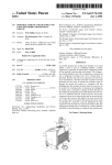
2.1 Exterior Dimension Diagram
<Classic10>
6-M6
0
35
5
140
12
35
293
1042
497
167
0
85
6
330
420
490
80
525
45
650
Unit : mm
I001666
Operation Section
7
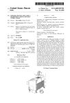
<Classic18>
6-M6
0
35
5
175
12
35
293
1042
497
167
0
85
95
330
420
490
80
525
45
650
Unit : mm
I001667
Operation Section
8
2.2 Technical Specifications
Technical Specifications
Classic18
Classic10
Electronic
Features
Control Panel
Electronic
Thermostat Control
Electronic
Cooling
Capacity
Rating Condition: 95 °F
60 %RH
2.92 kW (2520 kcal/h)
10,000 BTU/h
5.27 kW (4540 kcal/h)
18,000 BTU/h
Voltage Requirement
1 Phase, 115 V, 60 Hz
1 Phase, 208/230 V, 60 Hz
Total Power Consumption
1.1 kW
2.1 kW
Current Consumption
10.0 A
10.8/10.0 A
Recommended Fuse Size
15 A
15 A
NEMA Plug Configuration
5-15
6-15
Min.-Max. Voltage
105-125 V
198-250 V
Fan Type
Sirocco Fan
Air Volume
450 m3/h (265 CFM)
880/900 m3/h (518/530 CFM)
Motor Output
0.14 kW
0.35 kW
Type
Hermetic Rotary
Output
0.6 kW
1.10 kW
Refrigerant
Charge
R-22
0.48 kg (1.06 lbs)
0.72 kg (1.59 lbs)
Dimension
W x D x H *without air duct
492 x 673 x 1054 mm (19.4 x 26.5 x 41.5 inches)
Electrical
Characteristics
Fans
Compressor
Net Weight/Shipping Weight
66/83 kg (145/183 lbs)
Gauge
14 AWG (3-core)
Length
3.0 m (10 ft.)
Power Cord
76/94 kg (167/208 lbs)
1.8 m (6 ft.)
Condensate Tank Capacity
19 L (5 gal)
Operating
Conditions
Min.-Max. (@50 %RH)
70-105 °F (21-40 °C) (#1)
Max.Duct
Length (#2)
Cold Duct Hose
12 m (40 ft.)
15 m (50 ft.)
Hot Duct Hose
18 m (60 ft.)
18 m (60 ft.)
Max.Static
Pressure
Cold Duct Hose
0.33 IWG
0.52 IWG
Hot Duct Hose
0.13 IWG
0.25 IWG
With Condenser-Duct
High/Low
55 dB (A)
63 dB (A)
Without Condenser-Duct
High/Low
58 dB (A)
67 dB (A)
Max.Sound
Level
#1: When ambient temperature is lower than 77 °F, operation may cease due to anti-freeze protection activation.
#2: Confirm pressure drop of duct, filter with manufacturer's specifications.
I001709
Operation Section
9
2.3 Characteristics
(1) Cooling capacity curve
<Classic10>
<Classic18>
At 115 V
13.9 (3.5)
At 208/230 V
20.6 (5.2)
Cooling
Capacity
Cooling
Capacity
11.9 (3.0)
9.9 (2.5)
7.9 (2.0)
x103
BTU/h
19.0 (4.8)
17.5 (4.4)
15.9 (4.0)
x103
BTU/h
6.0 (1.5)
{kcal/h}
12.7 (3.6)
{kcal/h}
104 (40)
Dry Bulb
Temp.
Dry Bulb
Temp.
104 (40)
95 (35)
86 (30)
77 (25)
°F (°C)
59
(15)
68
(20)
77
(25)
86
(30)
95 (35)
86 (30)
77 (25)
°F
(°C)
°F (°C)
59
(15)
Wet Bulb Temp.
68
(20)
77
(25)
86
(30)
°F
(°C)
Wet Bulb Temp.
I001668
(2) Power consumption curve
<Classic10>
1.6
At 208/230 V
2.4
Power
Consumption
Power
Consumption
<Classic18>
At 115 V
1.4
1.2
2.2
2.0
1.8
1.0
kW
1.6
0.8
kW
95 (35)
86 (30)
77 (25)
°F (°C)
1.4
104 (40)
Dry Bulb
Temp.
Dry Bulb
Temp.
104 (40)
95 (35)
86 (30)
77 (25)
68
(20)
77
(25)
86
(30)
95
(35)
Wet Bulb Temp.
°F
(°C)
°F (°C)
68
(20)
77
(25)
86
(30)
95
(35)
°F
(°C)
Wet Bulb Temp.
I001669
Operation Section
10
(3) Cool air temperature difference curve
<Classic10>
<Classic18>
At 208/230 V
°F (°C)
27.0 (15)
27.0 (15)
25.2 (14)
25.2 (14)
Temperature Difference
Between Inlet and Outlet
Temperature Difference
Between Inlet and Outlet
At 115 V
°F (°C)
23.4 (13)
21.6 (12)
19.8 (11)
18.0 (10)
16.2 (9)
14.4 (8)
12.6 (7)
23.4 (13)
21.6 (12)
19.8 (11)
18.0 (10)
16.2 (9)
14.4 (8)
12.6 (7)
40
50
60
Relative Humidity
70
%
40
50
60
70
%
Relative Humidity
I001670
Operation Section
11
3. CONSTRUCTION
3.1 Internal Structure
<Classic10>
Control Panel
Room Thermistor (RTS)
Condenser Air Outlet
Cooling Air Duct
Housing for
Condenser Fan
Housing for
Evaporator Fan
Condenser Fan
and Motor
Evaporator
Condenser
Freeze Protection
Thermistor (CTS)
Capillary Tube
Compressor and
Accumulator
Drain Tank
Locking Swivel Caster
(Front)
Control Box
• Relay Board
• Capacitor
Full Drain Switch
Caster (Rear)
I001671
12
Operation Section
<Classic18>
Control Panel
Room Thermistor (RTS)
Condenser Air Outlet
Cooling Air Duct
Housing for
Condenser Fan
Housing for
Evaporator Fan
Condenser Fan
and Motor
Evaporator
Condenser
Freeze Protection
Thermistor (CTS)
Capillary Tube
Compressor and
Accumulator
Drain Tank
Locking Swivel Caster
(Front)
Control Box
• Relay Board
• Capacitor
• Auxiliary Relay
Full Drain Switch
Caster (Rear)
I001672
Operation Section
13
4. REFRIGERANT SYSTEM
4.1 Refrigerant System Construction
The component parts of the refrigerant system include the following:
• Compressor, Evaporator, Condenser, Accumulator, Capillary tube
The parts above are all connected by copper piping with brazed connections. The circled portion in the
figure below shows the part connections.
<Classic10>
Condenser
Evaporator
Condenser
Inlet Pipe
Evaporator Inlet Pipe
Capillary Tube
Evaporator Outlet Pipe
Compressor
Discharge Pipe
Connecting Pipe
(Evaporator to Compressor)
Condenser
Outlet Pipe
Connecting Pipe
(Condenser to Capillary Tube)
Compressor Suction Pipe
(Covered Insulation)
Accumulator
Compressor
Condenser
Flow of
Refrigerant
Accumulator
Capillary
Tube
Fan
Motor
Evaporator
Compressor
I001673
14
Operation Section
<Classic18>
Condenser
Evaporator
Condenser
Inlet Pipe
Evaporator Inlet Pipe
Evaporator Outlet Pipe
Compressor
Discharge Pipe
Capillary Tube
Condenser
Outlet Pipe
Connecting Pipe
(Evaporator to Compressor)
Compressor
Connecting Pipe
(Condenser to Capillary Tube)
Accumulator
Condenser
Compressor Suction Pipe
(Covered Insulation)
Flow of
Refrigerant
Accumulator
Capillary
Tube
Fan
Motor
Compressor
Evaporator
I001674
Operation Section
15
4.2 Compressor
• The compressor used for the unit is hermetically sealed. The compressor and the compressor
motor are in one casing.
(1) Compressor construction
• The construction of a rotary type compressor is divided into two mechanisms; the drive
mechanism (compressor motor), and the compression mechanism (compressor). When the
rotor shaft of the motor (drive mechanism) turns, the roller (compression mechanism) rotates to
compress the refrigerant.
To Condenser
From Evaporator
Accumulator
Terminal
Strainer
Stator
Rotor
Cylinder
Roller
Lubricator
Blade
Discharge Valve
Oil
I001675
16
Operation Section
(2) Basic compressor operation
• The roller (compression mechanism) is set
eccentrically with a certain distance given from
the axis of the center of the cylinder. A spring
Discharge
Hole
Discharge
Valve
loaded blade is mounted on the cylinder. The
Spring
Suction
Hole
Blade
roller turns to compress the refrigerant in the
space between the cylinder and eccentrically
mounted roller. The blade is in contact with the
Shaft
Roller
roller by means of spring force. The blade
Cylinder
I000510
partitions the space between the suction side
and the discharge side to keep compressed refrigerant from returning to the suction side. There
is no suction valve. The discharge valve is designed not to open until the pressure of the
refrigerant within the cylinder reaches or exceeds discharge side pressure. As a result, the
discharge valve prevents the backward flow of refrigerant gas.
Operation Section
17
(3) Operation
1) Start of compression
Discharge
Valve
1) The cylinder is filled with low pressure gas.
Blade
2) Since pressure in the discharge chamber is
higher than in the cylinder, the discharge
valve is kept closed.
Roller
I001676
2) Suction and compression
Discharge
Valve
1) The pressure in the cylinder increases
gradually.
Blade
2) Refrigerant suction begins on the suction
side of the cylinder.
3) The discharge valve remains closed.
Roller
I001677
3) Discharge
Discharge
Valve
1) The pressure in the cylinder exceeds that in
the discharge chamber, and the discharge
Blade
valve opens.
2) On the suction side, refrigerant suction
continues.
Roller
I001678
4) Completion of compression
1) When compression is completed, all of the
Discharge
Valve
refrigerant has been drawn from the suction
Blade
chamber.
2) Operation then returns to step 1) (Start of
compression) and the above process of
suction
Roller
I001679
and
compression
repeatedly in succession.
continues
18
Operation Section
(4) Compressor lubrication
• The lubrication system is comprised of a
hollow shaft, an oil scraper mounted at the end
face, hollow shaft, a shaft journal (shaft
Rotor
bearing), and the lubrication groove for the
shaft journal. The lubrication groove is wider
than the oil hole. When the shaft turns, oil is
scraped upward by the oil scraper along the
Hollow Shaft
Eccentric Shaft
Cylinder
Roller
inside diameter of the hollow shaft. The oil is
fed through the oil hole by centrifugal force,
then supplied to the lubrication groove for each
shaft journal, lubricating the bearing. In this
lubrication system, oil enters into each bearing
separately and returns to the oil reservoir. This
system
effectively
temperature
increases,
prevents
and
Oil Feed Groove
Oil Hole
Oil Scrapper
bearing
offers
high
I001680
reliability. In addition, the specially treated
shaft journal keeps the bearing from being damaged during high temperature operation.
4.3 Condenser
• The condenser is a spine-fin type heat
exchange device consisting of copper tubes
passing through an aluminum fin.
• Heat is given off and absorbed by air being
pulled across the condenser fins by the
centrifugal fan. The air is then expelled through
the exhaust air duct.
I001681
Operation Section
19
4.4 Capillary Tube
• The capillary tube is a long thin tube that
utilizes line flow resistance as an expansion
High Temp./High Press.
Liquid Refrigerant
valve. The length and the inner diameter of the
capillary tube are determined according to the
capacity of the refrigeration system, operating
conditions, and the amount of refrigerant. The
high-pressure,
high-temperature
liquid
Low Temp./Low Press.
Gas and Liquid Mixture
refrigerant sent from the condenser expands
I001822
rapidly as the refrigerant is sprayed out through
the fixed orifice in the capillary tube. As a result, the temperature and state of the refrigerant
become low and mist-like, and therefore evaporates easily.
4.5 Evaporator
• The evaporator, like the condenser, is a heat
exchanger covered with spine fins. Heat is
removed from the air being pulled across the
evaporator by the centrifugal fan. The resulting
cool air is expelled through the cooling air
ducts.
I001682
4.6 Accumulator
• The accumulator is mounted on the suction
From Evaporator
gas piping between the evaporator and the
compressor. The accumulator separates the
liquid refrigerant from the gas refrigerant,
allowing only the gas refrigerant to enter the
compressor. In the accumulator, suction gas is
led into a cylindrical vessel where the speed of
the gas is decreased. This process separates
To Compressor
I000514
the refrigerant contained in the gas by the force
of gravity, causing the refrigerant to accumulate at the bottom of the vessel. As a result, the
compressor is protected from possible damage caused by liquid refrigerant intake.
Operation Section
20
5. ELECTRICAL SYSTEM
5.1 Circuit Diagram
<Classic10>
R
MF
MC
IOLF
G
S
C
G
1
OLC
2
CF
TB2
L-
CC
Output Signal
1
2
1
2
L+
AUX2
EE+
On Board
Controller
Fine Alarm
Input
11
CN23
5
CN25
1
1
5
520D2
1 1 CN21 3
CN22
CN24
2
1
1
COM
52CT
520D1
52ID
F1
Dip Switch
Ground (G)
RB
115V
T
T
R
AP
R
TB1
ON
5
1
1
3 4
CN12
3
1
CN11
3
1
2
CN16
1
CN15 52CM
3
1
2
4
G
3
Control Box
CN
Jumper
Line
CTS
TB1
TB2
RB
MF
MC
CF
CC
OLC
RTS
Drain Tank SW
Terminal Block1
Terminal Block2
Relay Board
Fan Motor
Compressor Motor
Capacitor for Fan Motor
Capacitor for Compressor
Overload Protector
AUX1
CN
CTS
RTS
G
CB
Connector for Option
Drain Pump
Freeze Protection Thermistor
Room Thermistor
Ground
Control Board
SW1
SW2
SW3
SW4
COOL ON/OFF Switch
FAN Switch
SET TEMP Switch
SET TEMP Switch
LED1
LED2
LED3
LED4
R111
R112
DIG
R110
Control Board
R109
CB
1 2
CN13
5
AC115V
1PHASE
60Hz
5
CN01
11
CN17
1
1
R101
R102
R103
R104
R105
R106
R107
R108
SW1
SW2
SW3
SW4
CN9
11
10
9
8
7
6
5
4
3
2
1
CN8
5
4
3
2
1
I001683
Operation Section
<Classic18>
21
R
MF
MC
IOLF
G
S
C
G
1
OLC
2
CF
TB2
L-
1
Output Signal
CC
2
13
1
RX
2
14
L+
AUX2
EE+
On Board
Controller
A1
A2
Fine Alarm
Input
11
CN23
5
CN25
1
1
5
520D2
1 1 CN21 3
CN22
CN24
2
1
1
COM
52CT
520D1
52ID
5
3
AC115V
1PHASE
60Hz
3 4
CN12
1
CN11
3
1
2
CN16
1
CN15 52CM
3
1
2
4
G
3
Control Box
CN
Jumper
Line
CTS
TB1
TB2
RB
MF
MC
CF
CC
OLC
RTS
AUX1
Drain Tank SW
Terminal Block1
Terminal Block2
Relay Board
Fan Motor
Compressor Motor
Capacitor for Fan Motor
Capacitor for Compressor
Overload Protector
CN
CTS
RTS
G
CB
RX
Connector for Option
Drain Pump
Freeze Protection Thermistor
Room Thermistor
Ground
Control Board
Auxiliary Relay
SW1
SW2
SW3
SW4
COOL ON/OFF Switch
FAN Switch
SET TEMP Switch
SET TEMP Switch
LED1
LED2
LED3
LED4
R111
R112
DIG
R110
Control Board
R109
CB
1 2
1
1
AP
230V
R
5
CN01
CN13
5
T
R
TB1
ON
11
CN17
1
T
F1
Dip Switch
1
Ground (G)
RB
R101
R102
R103
R104
R105
R106
R107
R108
SW1
SW2
SW3
SW4
CN9
11
10
9
8
7
6
5
4
3
2
1
CN8
5
4
3
2
1
I001684
22
Operation Section
5.2 Control Box and Relay Board
TB2: Terminal Block2
RB: Relay Board
G: Ground
TB1: Terminal Block1
CC: Capacitor for Compressor
CF: Capacitor for Fan Motor
I001685
CN15 CN16 CN14 CN02
CN03
CN04 CN11 CN12
CN13
4-Position Dip Switch
CN17
52CM
CN25
CN01
Relay Board Fuse (5A)
CN24
CN21
CN22
CN23
“OFF” Position
I001686
Operation Section
23
5.3 Basic Operation
(1) Control panel
• Before operating the unit, it is important to be familiar with the basic operation of the control
panel.
5
6
1
2
4
7
3
1
COOL ON/OFF Button
Activates/deactivates the cool mode; turns the unit off.
2
FAN Button
Activates/deactivates the fan only mode; turns the unit off.
3
SET TEMP Buttons (/)
Increases/decreases the temperature set point during cool mode.
4
Room Temperature/
Set Point Display
Shows a blinking set point temperature for five seconds, then continuously
indicates room temperature.
5
Temperature Scale LED
Illuminates to indicate the current temperature being displayed is either in °C or °F.
6
ON LED
Illuminates during fan only mode and cool mode using fan operate mode.
7
AUTO LED
Illuminates during cool mode using fan stop mode.
[LED Display Indication] In normal operation, LED displays the following indication.
Display
Indication
Conditions
Right decimal segment is on
Power stand by or during fan only mode
Indicates room temperature
when display is solid.
(Left fig. : Room temp. at 78 °F)
During cool mode
Indicates set point temperature
when display is flashing.
(Left fig. : Set Point temp. at 75 °F)
During set point temperature adjustment
or cool mode on.
(5 seconds)
I001710
< NOTE >
• The room temperature display range is from 0 to 109 °F.
(When displayed in “°C ” the range is from -9 °C to 60 °C )
• In Fahrenheit only, when the display value is greater than 99 °F, 100 °F, 101 °F, and 109 °F are
displayed as “00”, “01”, and “09” respectively.
24
Operation Section
(2) Fan only mode
• When the FAN button on the control panel is pressed, the FAN “ON” LED illuminates, and the
fan operates. At this time, the compressor is off, and only the fan is in operation. When the FAN
button is pressed again, the fan stops.
(3) Cool mode
• When the COOL ON/OFF button is pressed, the FAN “ON” LED illuminates, and room
temperature is shown on the display. At this time, the compressor and fan begin to operate to
provide cooling. When the COOL ON/OFF button is pressed again, the compressor and fan
stop.
• When the COOL ON/OFF button is pressed in fan only mode, room temperature is shown on
the display, and the compressor operates to provide cooling. If room temperature reaches the
set temperature during cooling operations, the compressor stops, and only the fan continues to
operate. (Fan operate mode: * Initial setting)
< NOTE >
The fan only mode will not operate after the cool mode has been activated. Once the cool mode
is activated, the unit cannot be turned off by pressing the fan button. Rather, the COOL ON/OFF
button must be pressed.
*Fan stop mode
- In fan stop mode, if room temperature reaches the set temperature during cooling operations,
both the compressor and fan stop. The fan stop mode setting can be changed using the dip
switch on the relay board. (For details, refer to page 26). During cooling operations when in
the fan stop mode, the FAN “AUTO” LED illuminates.
(4) Change temperature mode “°C” and “°F”
• The temperature display can be switched between “°C” and “°F” by holding the SET TEMP
arrow buttons (U, V) and the FAN button down simultaneously for at least three seconds.
(5) Diagnostic code
• Most of the diagnostic codes can be RESET by holding the SET TEMP arrow buttons (U, V)
down simultaneously for at least three seconds. (For details, refer to “Self-Diagnosis Codes”.)
Operation Section
25
5.4 Relay Board
• The relay board contains the compressor and fan on relays, in addition to a step-down
transformer that converts the line voltage (Classic10: 115 VAC, Classic18: 208/230 VAC) to 12
V. This voltage is then converted from AC to DC and used for relay coil activation. The 12 V (DC)
power is sent to the control panel assembly, further being reduced to 5 V for the system logic.
Lastly, the relay board also contains the dip switch.
(1) Power supply requirements
• The Classic10 requires a single-phase 115 V, 60 Hz power supply, while the Classic18 requires
a single-phase 208/230 V, 60 Hz power supply.
(2) Relay board fuse
• The relay board fuse is the only serviceable component on the relay board assembly. This fuse
provides protection against damage to the step-down transformer. The fuse must be replaced
with the exact same part, or a suitable equivalent.
- Fuse Specifications: 5A 250 VAC
CAUTION
Failure to use the exact same fuse may result in damage to the unit and/or components, and will
also void the unit warranty.
(3) Input signal
• The relay board receives inputs from the control panel, sensors, and external devices to perform
device control.
Control Panel Input
Symbol
Indication
SW1
ON/OFF Button
SW2
FAN Button
SW3
SW4
SET TEMP U
Function
On/off control for unit operation. Turns the unit on and off.
Changes the fan control mode between continuous and automatic
on/off control.
Increases the set temperature.
Button
SET TEMP V
Button
Connector
Decreases the set temperature.
CN17
Operation Section
26
Sensor Input
Specification
Symbol
Type
RTS
Room Thermistor
Characteristic
Freeze Protection
CTS
Thermistor
“Short” Detection
“Open” Detection
5k Ω at 77 °F (25 °C) 181 °F (83 °C) or
-29 °F (-34 °C) or
B=3,970 K
less
more
5k Ω at 77 °F (25 °C) 181 °F (83 °C) or
-29 °F (-34 °C) or
B=3,970 K
less
more
Connector
CN11
CN12
External Input Signal Specification
Symbol
AUX2
Signal
Specification
Fire
On: Between 10 to 20
Alarm
mA at DC12 V
Input
(Off: No signal)
TANK
Tank Full
FULL S/W
Switch
AUX1
On: Between 10 to 20
Function
Connector
On: Activates “Defect control”
(Contact: Normally open)
On board buzzer sound
Off: Activates “Defect control”
mA at DC12 V
(Contact: Normally closed)
(Off: No signal)
LED shows “FL”, Output signal “ON”
External
On: Between 10 to 20
Pump
mA at DC12 V
Failure
(Off: No signal)
CN15
LED shows “AL”, Output signal “ON”
CN16
Off:
1) < 180 sec.: Compressor stops.
CN13
2) 180 sec.<: Compressor stops.
LED shows “AS” output signal “ON”
(4) Dip switch setting
• The controller is equipped with a four position dip switch that defaults in the OFF position. The
dip switch can be set to configure the following functions:
ON
1
2
3
4
Symbol
DSW4
Item
Buzzer
Function
On --- Disable “onboard buzzer”
Off --- Valid
DSW3
-
N/A
DSW2
-
N/A
DSW1
Fan Mode
Change Fan Mode
On --- Fan stop mode (Fan AUTO)
Off --- Fan operate mode (Fan ON)
I001711
Operation Section
27
5.5 Control Specifications
(1) Fan control
• When the FAN button is pressed, the 52ID (fan motor on/off) relay on the relay board turns on,
operating the fan.
• For the Classic18, the 52ID relay turns the auxiliary relay on to operate the fan.
- 52ID (Fan motor On-Off) relay output specification: 5 A at AC250 V
(2) Compressor start control
• When the ON/OFF button is pressed, the 52CM relay on the relay board turns on, operating the
compressor.
- 52CM (Compressor On-Off) relay output specification: 20 A at AC250 V
(3) Anti-freeze control
• Anti-freeze controls turns the compressor on and off by turning the 52CM relay on in accordance
with the freeze protection thermistor (CTS) temperature. As a result, decreases in cooling
performance due to frost buildup on the evaporator are prevented.
• Compressor off conditions: Freeze protection thermistor (CTS) temperature ≤ 29 °F (-1.5 °C)
• Compressor on (recovery) conditions: CTS temperature ≥ 59 °F (15 °C)
ON
52CM
OFF
29 °F
(-1.5 °C)
59 °F
(15 °C)
CTS temperature
(Evaporator out temperature)
I001687
28
Operation Section
(4) Compressor time delay control (compressor protection)
• Compressor protection consists of a time delay program within the microprocessor. This
program prevents a heavy load from being applied to the compressor motor when restarting the
unit (cool mode) after a very short period of time. This “delay” is in effect any time the
compressor is turned on by either the COOL ON/OFF button, or power interruption restart
(automatic recovery.)
- Time Delay Program Specifications: 120 sec.
1st Time (After initial set up, reset circuit breaker, etc.)
Compressor turns off and on immediately (within 120 sec.)
[Example]
Turn ON
Compressor turns off and on more than 120 sec. later
ON
Controller
OFF
Status
Compressor ON
Status
OFF
(52CM)
No Delay Time
(less than 5 sec.)
Delay Time
(120 sec.)
No Delay Time
(Less than 5 sec.)
Stop
(for Extended Period)
Delay Time
(120 sec. after last turn off)
Reference: Initial turn on
Within: 120 sec. after (the power cord is connected to) the power supply, the compressor will start with delay timer.
After: 120 sec. since (the power cord was connected to) the power supply, the compressor will start without delay timer.
I001688
(5) Automatic restart and recovery function
• The microprocessor contains a feature that automatically restart the unit after power is lost and
regained, and also has memory to store and recover operation status in the even of a power
loss.
Status of memory during power interruption
• When the input power is off, the status items below are saved in the memory.
- Running status (on or off)
- Operating mode: Cool mode or fan only mode
- Set temperature
- Temperature mode (°F or °C)
- Fan mode: Fan operation mode (fan on) or fan stop mode (fan auto)
Operation Section
29
(6) Temperature control
• During cool mode, temperature control changes the 52CM (compressor on/off) relay status
according to RTS temperature in the available range (-4 to 140 °F (-20 to 60 °C)).
ON
52CM
(Compressor Relay)
OFF
(Set Temp. -3 °F)
(Set Temp. -1.7 °C)
Set Temp
Inlet Air Temperature
When compressor operation continues within this range for more
than 5 minutes, the 52CM relay stops.
I001689
(7) Fire alarm signal control
• When receiving the signal from the fire alarm control panel, the buzzer sounds, and the 52CT
(signal output) relay on the relay board turns on.
Operation Section
30
5.6 Self-Diagnostic Codes
• Self-diagnostic codes are displayed on the control board under the following conditions.
Indication
No. 1
No. 2
Condition
When the drain tank switch is activated, the
LED displays “FL” and the unit turns off
automatically.
Once emptying the drain tank procedure is
completed and ON/OFF has been pushed, unit
returns to normal operation.
When the fire alarm control panel input signal
is CLOSED, the unit turns off, the LED displays
“AL”, and the buzzer turns on.
This condition returns to normal when the input
signal is once again OPEN, and unit has been
RESET.
Output
Signal
Buzzer
(On Board)
Yes
No
Yes
Yes
Yes
No
Yes
No
Yes
No
To RESET, hold down the SET TEMP buttons
(/) simultaneously for 3 seconds, and the
controller returns to normal status.
No. 3
Improper hose connection (including kink or
blockage) or a defect in the condensate pump
for more than 180 seconds will display "AS" on
the LED resulting the compressor to stop
immediately; however, fan will continue to
operate.
Normal condition is resumed when condensate
pump or hose connection is fixed, and the unit
has been RESET.
To RESET, hold down the SET TEMP buttons
(/) simultaneously for 3 seconds, and the
controller returns to normal status.
No. 4
No. 5
When room thermistor becomes open or
shorted, display shows “E1” and cool mode
operation is off. Display and cool mode
operation are returned to normal operation after
condition is corrected.
When freeze protection thermistor becomes
open or shorted, display shows “E2” and cool
mode operation is off. Display and cool mode
operation are returned to normal operation after
condition is corrected.
I001712
Operation Section
31
5.7 Compressor
(1) Compressor motor
• The compressor motor is a single-phase motor
and is contained within the same housing as
the compressor.
Specifications: Classic10
- Rated Voltage: 115 V
- Rated Output: 600 W
Specifications: Classic18
- Rated Voltage: 208/230 V
- Rated Output: 1100 W
I001690
(2) Compressor overload relay
• An external compressor overload relay is used
Bimetal
to protect the compressor motor. This relay is
mounted within the connector housing that
attaches to the top of the compressor. The
Points
relay interrupts the flow of current when there
is an overload condition and, high temperature
Terminal
builds up in the compressor.
I001691
Model
Operating Temperature
Non-Operating Limit at 176 °F
Marking
OFF (Open Contacts)
ON (Closed Contacts)
(80 °C) (A)
Classic10
275 °F (135 °C)
156 °F (69 °C)
10.0
MST00AGU-9014
Classic18
293 °F (145 °C)
156 °F (69 °C)
13.0
MRA98869
Operation Section
32
5.8 Fan Motor
• The fan motor is a single phase, induction type.
The motor rotates the fan on both the
evaporator side and the condenser side at the
same time.
• The following table shows the specifications of
the fan motor used for each model.
Specifications:
Classic10
Classic18
Rated Voltage
115 V 60 Hz
208/230 V 60 Hz
Rated Output
140 W
350 W
I001692
< NOTE >
An internal overload relay is used to protect the fan motor. This relay is built into the fan motor and
interrupts the flow of current when there is an over current situation, or if abnormally high
temperature builds up in the fan motor.
5.9 Capacitor
• The capacitor is used to improve the rotational
power of the fan motor and compressor at
startup. The specification for each capacitor is
shown below.
Model
Classic10
Classic18
Rated
Capacitance
Voltage (V)
(µF)
For Fan Motor
200
16
For Compressor
370
25
For Fan Motor
400
10
For Compressor
370
25
Capacitor
Check capacitance
I001693
Operation Section
33
5.10 Auxiliary Relay (For Classic18 Only)
• The auxiliary relay is normally closed when the
unit is in operation (fan or cool), and supplies
power to the fan motor.
• When current flows across A1 and A2,
terminals 13 and 14, 23 and 24, 33 and 34,
43/41 and 44/42 conduct.
Specifications:
- Rated Voltage: AC230 V
- Rated Current: 10 amps
13
A1
14
A2
I001694
5.11 Temperature Thermistor
• The
room
thermistor
(RTS)
is
installed
upstream of the evaporator, and detects
evaporator inlet temperature as a resistance
value.
• The freeze protection thermistor (CTS) is
installed in the evaporator outlet piping, and
detects low temperature on the evaporator as
a resistance value.
Type
Room Thermistor (RTS)
I001695
Specification
Characteristic
5k Ω at 77 °F (25 °C)
B=3,970 K
Freeze Protection
5k Ω at 77 °F (25 °C)
Thermistor (CTS)
B=3,970 K
“Short” Detection
“Open” Detection
181 °F (83 °C) or more
-29 °F (-34 °C) or less
181 °F (83 °C) or more
-29 °F (-34 °C) or less
Operation Section
34
5.12 Drain Tank Switch
• The drain switch activates and stop the operation of compressor motor and fan motor when
approximately 4.4 gal (16 L) of drain water accumulates in the drain tank. At the same time,
control panel display "FL", and compressor and fan operations stop. This system uses a 250 V,
0.1 A rating micro switch for this function.
• When approximately 4.4 gal (16 L) of drain water accumulates in the drain tank, the drain tank
base plate, which is supported at fulcrum (a), is pushed down in the direction of the arrow.
• When the drain tank base plate is forced down, “portion A”, located at the top of the drain tank
base plate, turns off micro switch contacts (1)-(2).
Evaporator
Portion “A”
Drain Pan
Full Drain Switch
NC (2)
Relay
Board
(CN16)
2
1
NC
NO 3
COM
Drain Tube
C (1)
Drain Tank
Drain Water
Spring
a
Base
Base Plate
I001696
Repair Section
35
6. PRECAUTIONS FOR SAFETY
6.1 Definition of Terms
WARNING
CAUTION
NOTE
Describes precautions that should be observed in order to prevent injury to
the user during installation or unit operation.
Describes precautions that should be observed in order to prevent damage to
the unit or its components, which may occur during installation or unit
operation if sufficient care is not taken.
Provides additional information that facilitates installation or unit operation.
6.2 General Precautions
WARNING
• When necessary, electrical work should only be performed by qualified electrical
personnel. Repair to electrical components by non-certified technicians may result in
personal injury and/or damage to the unit. All electrical components replaced must be
genuine MovinCool parts, purchased from an authorized reseller.
• When handling refrigerant, always wear proper eye protection and do not allow the
refrigerant to come in contact with your skin.
• Do not expose refrigerant to an open flame.
• The proper electrical outlet for MovinCool units must be equipped with a “UL” approved
ground-fault breaker to prevent electrical shock from the unit.
• When brazing any tubing, always wear eye protection, and work only in a well ventilated
area.
36
Repair Section
7. TROUBLESHOOTING
7.1 Troubleshooting
• To accurately troubleshoot the problem, it is important to carefully confirm the nature of the
problem.
Typical problems are:
- Insufficient cooling
- Unit does not start (operate)
- Drain water overflow
- Abnormal noise or vibration
- Other
(1) Insufficient cooling
• Cooling system problem generally results from electrical or mechanical components such as fan
motor, compressor, or control switch.
< NOTE >
• There is a possibility that insufficient cooling is caused by air filter clogging. First, verify that the
air filter is not clogged.
• Check the power supply due to the possibility of a power source failure.
Repair Section
Possible Cause
Symptom
Check Area
1. Usage conditions
(high temperature)
2. Dirt in condenser or
Compressor
Operates
Air Volume
Review the installation
place.
Poor heat exchange
Clean fins.
3. Frost in refrigeration cycle
Clogging at the frost section
Replace clogged section.
4. No temperature difference
Insufficient refrigerant
Check the leaking part,
evaporator
between evaporator and
then repair and charge
condenser
refrigerant.
1. Coil resistance (0 Ω or ∞ Ω)
Normal
Remedy
Cause
Operation near usage limits
37
Short or open circuit
Replace compressor.
(In case of short, check
the compressor relay on
the relay board)
Compressor
Does Not
Operate
2. Compressor on/off relay
Open circuit or poor contact
Replace relay board.
3. Capacitor for compressor
Capacitor malfunction
Replace capacitor.
4. Compressor overload relay
Overload relay fault
Replace overload relay.
5. Voltage
Low voltage
Repair power.
1. Coil resistance of fan motor
Short or open circuit
Replace fan motor.
Open circuit or poor contact
Replace relay board.
Open circuit or poor contact
Replace auxiliary relay.
(52CM) on the relay board
(0 Ω or ∞ Ω)
2. Fan motor on-off relay (52ID)
No Air
on the relay board
3. Auxiliary relay in the control
box (Classic18 only)
Insufficient
(no voltage)
board.
1. Air filter
Clogged air filter
Clean air filter.
2. Evaporator
Clogged evaporator or
Repair and clean fins, or
crushed fins
replace.
3. Duct connection state
Improper connection
Repair duct connection.
4. Fan motor
Poor rotation
Replace motor.
Air Volume
Insufficient
Air Volume
No excite coil on the relay Check and replace relay
(2) Unit does not start (operate)
< NOTE >
• In this case, there is a possibility of safety device activating due to the clogged air filter. So be
sure to first clean the air filter and then start up again to confirm if the problem lies with the air filter.
• Check the installation site for operating temperature and installation space (unobstructed airflow).
• In the case above, there is the possibility of a safety device activating due to a clogged air filter.
First clean the air filter and then verify that the unit starts.
Repair Section
38
Possible Cause
Symptom
Does Not
Operate at
All
Check Area
1. Voltage
Power failure
Repair power supply.
2. Ground fault breaker trip
Ground fault or defective
Repair ground fault
ground fault
section.
Reset or repair breaker.
LED Display
Turns Off
Remedy
Cause
3. LCDI power cord trip
LCDI power cord trip
Reset power cord.
Replace power cord.
4. Fuse
Fuse blown
Repair shorting section.
Replace fuse.
1. Display code “FL”
2. Display code "AS"
Drain tank is filled with drain
Discharge the drain
water
water.
Improper routing of drain
Repair drain hose, then
hose
reset unit.
Defective condensate pump
Repair or replace
condensate pump, then
reset unit.
Missing jumper connector
Connect jumper
connector.
LED
Display
Display
Shows Error
Turns On
Codes
3. Display code “AL” with beep Input signal (from fire alarm)
sound
continuously
4. Display code “AL” without Input signal (from fire alarm)
beep sound
5. Display code "E1"
Check external input
signal, then reset unit.
Reset unit.
on from before
Improper room thermistor
Check connection.
connection
6. Display code "E2"
Defective room thermistor
Replace room thermistor.
Improper freeze protection
Check connection.
thermistor connection
Stops
Immediately
LED
Displays
Normally
Stops after
LED
Running a
Displays
While
Normally
Defective freeze protection
Replace freeze protection
thermistor
thermistor.
1. Fan motor on/off relay (52ID) Open circuit or poor contact
Replace relay board.
on the relay board
2. Fan motor insulation
resistance
Insulation failure on fan
Replace fan motor.
motor
1. Coil resistance of fan motor
Defective fan motor
Replace fan motor.
2. Compressor temperature
Compressor overload relay
Replace compressor.
operates due to compressor
Service dirty areas.
(abnormally high)
malfunction
3. Dirt on air filter or condenser
Insufficient refrigerant or gas
Repair and charge
leakage
refrigerant.
Insufficient condenser
Clean condenser.
cooling
Repair Section
39
(3) Drain water overflow
Possible Cause
Symptom
Check Area
Cause
Remedy
1. Drain pan
Cracks in drain pan
Check and repair.
2. Water level in drain pan
Clogged drain hose
Check and replace.
3. Drain hole
Reversed air flow from drain
Insert a trap on the
hole
discharge drain hose.
Reversed air flow from drain
Clean air filter.
Overflow from Unit
4. Clogged air filter
hole due to the excessive
negative pressure inside of
the unit
(4) Abnormal noise or vibration
• To prevent from abnormal noise or vibration, first carefully determine the source. Next, devise
proper countermeasures to eliminate the noise or vibration and prevent reoccurrence.
Possible Cause
Symptom
Check Area
1. Fan
Abnormal Noise or
Vibration.
Cause
Remedy
Fan interference
Repair interfering section.
Fan deformation
Replace fan.
2. Compressor fixing nuts
Looseness of nuts
Tighten nuts further.
3. Piping
Pipe interference
Repair interfering section.
4. Panel fixing screws
Looseness of screws
Tighten screws further.
40
Repair Section
7.2 Basic Inspection
• Perform the following inspections before disassembly.
(1) Power source voltage inspection
• Check the power supply voltage.
- Classic10: Single phase 115 V (60 Hz)
- Classic18: Single phase 208/230 V (60 Hz)
• Check the operation and condition of the fuse or circuit breaker for the power source.
(2) Air filter inspection
• Remove the air filters and check the element.
If dirty, wash the element.
Air Filter
(for Evaporator)
Air Filter
(for Condenser)
I001697
(3) Fin inspection
• Remove the air filters and inspect the spine fins
for any dirt, dust, lint, or debris that may cause
poor cooling performance. If spine fin cleaning
is necessary, it is recommended that this
service be performed by a qualified service
technician.
I000526
Repair Section
41
(4) Operating environment inspection
• Check the environment around the unit.
Inlet air:
- Temperature
104
°F
(40°C)
or
Temperature
Over 104 °F
(40 °C)
lower
Humidity 50 % or lower
• Do not operate the unit above the temperature
Humidity
Over 50 %
and humidity specified above.
I001698
(5) Cooling capacity inspection
• Measure the temperature difference between
the evaporator inlet and the cooling air duct
Cooling Air Duct
Thermometer
outlet. If the difference is out of the range
shown in the graphs on page 10, proceed with
the remedy suggested in the troubleshooting
chart on page 37.
Inlet of Evaporator
I001699
Repair Section
42
7.3 Compressor Inspection
(1) Compressor motor inspection
• Measure resistance across the terminals of the
C
compressor motor.
2
S
Resistance at 77 °F (25 °C)
Model
R-C
C-S
Classic10
Approx. 0.7 Ω
Approx. 9.2 Ω
Classic18
Approx. 1.5 Ω
Approx. 4.0 Ω
1
R
I001700
• If the measured resistance is not equal to the
standard values listed above, replace the compressor. The compressor has an external
overload relay. The overload relay should be operational if the above resistance is obtained
under normal temperature. For overload relay specifications, refer to the chart below.
(2) Overlord relay inspection
• Check for continuity across two terminals of the
overload relay. At normal temperature, there
should be continuity across the terminals.
Model
Operating Temperature
OFF (open contacts)
ON (closed contacts)
Classic10
275 °F (135 °C)
156 °F (69 °C)
Classic18
293 °F (145 °C)
156 °F (69 °C)
• If there is no continuity across the terminals,
I001701
replace the overload relay.
7.4 Fan Motor Inspection
• Measure resistance across the terminals of the
fan motor.
Model
Resistance at 68 °F (20 °C)
CF1-TBT
CF2-TBT
Classic10
Approx. 7 Ω
Approx. 9 Ω
Classic18
Approx.14.4 Ω
Approx. 12 Ω
• If the measured resistance is not equal to the
standard values listed above, replace the fan
motor.
TBT (THS)
CF2
CF1
I001702
Repair Section
43
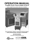
7.5 Capacitor Inspection (For Fan Motor and Compressor)
(1) Ohmmeter method
• Set the ohmmeter to the 10 MΩ range. Place
the two probes against the two terminals of the
Control Box
capacitor. At first, the ohmmeter indicates
small value, then the reading should gradually
increase towards infinity (∞), indicating that the
capacitor is charging. If the reading indicates
infinity immediately (open), or the ohmmeter
CC: Capacitor for
Compressor
CF: Capacitor for
Fan Motor
I001703
fails to move from 0 Ω (shorted), replace the
capacitor.
(2) Capacitance tester method
• Use a capacitance tester to check the
capacitor for the values indicated below. If the
value tested is not within 10 % of the indicated
capacitance, replace the capacitor.
Model
Classic10
Classic18
Rated
Capacitance
Voltage (V)
(µF)
For Fan Motor
400
10
For Compressor
370
25
For Fan Motor
200
16
For Compressor
370
25
Capacitor
Check capacitance
I001693
WARNING
Properly discharge the capacitor(s) before and after testing. Failure to discharge the
capacitor may cause damage to the test equipment and/or unit, and result in personal
injury (electrical shock) or death.
Repair Section
44
7.6 Auxiliary Relay Inspection (For Classic18 Only)
• Measure the resistance across terminals A1
and A2.
- Standard resistance: 1.6 ~ 2.4k Ω
• If the resistance is out of the range specified
above, replace the auxiliary relay.
• Check the continuity across the terminals 13
and 14, when the test button is depressed as
well as when released.
13
Terminals
State of Reset Switch
Continuity
Depressed
Continuity
Released
No continuity
13-14
14
(Reference)
Depressed
Continuity
Released
No continuity
Depressed
Continuity
Released
No continuity
43/41-
Depressed
Continuity
44/42
Released
No continuity
23-24
33-34
A1
A2
I001694
7.7 Full Drain Switch Inspection
• Depress the full drain switch to check for
continuity. If there is no continuity, replace the
Full Drain Switch
switch.
NC (2)
• Normally: Continuity across 1 and 2.
• Switch Depressed: Continuity across 1 and 3.
Relay
Board
(CN16)
2
1
NC
NO 3
COM
C (1)
I001745
Repair Section
45
7.8 Thermistor Inspection
• Use an ohmmeter to check the resistance
across
the
2-pin
connector
at
normal
temperature (77 °F (25 °C)).
Specification
Type
Room Thermistor (RTS)
Characteristic
5k Ω at 77 °F (25 °C)
B=3,970 K
Freeze Protection Thermistor
5k Ω at 77 °F (25 °C)
(CTS)
B=3,970 K
I001695
7.9 Wiring Connection Inspection
• While referring to the wiring diagrams, check the connection of each wire.
CAUTION
Secure the wires using clamps to prevent contact with the edges of the structure, etc. Secure the
wires in the same position as prior to removal.
7.10 Refrigerant System Inspection
• In most cases, the most probable causes of insufficient cooling are a clogged system, leakage,
or an incorrect amount of refrigerant. In such cases, inspect the system according to the
following procedure.
(1) System clog inspection
• Check refrigerant system components (including piping) that could be clogged with refrigerant.
When a component is clogged with refrigerant, only the clogged part will be partially frosted. In
such cases, replace the part in question.
(2) Refrigerant leak inspection
• Each time the refrigerant system is installed or repaired, use an electronic gas leak tester to
carefully check all connections, and each component for leaks.
46
Repair Section
8. DISASSEMBLY (For Classic10)
8.1 Parts Construction
<Classic10>
Room Thermistor
Upper Panel
Cooling Air Duct
Control Panel
Right Side Panel
Front Panel
Air Filter
Housing for
Condenser Fan
Air Filter
Housing for
Evaporator Fan
Condenser Fan
and Motor
Left Side Panel
Rear Panel
Drain Pan
Drain Tank
Service Panel
Locking Swivel Caster
Full Drain Switch
Caster
I001704
Repair Section
47
8.2 Disassembly
1) Remove the drain tank.
Cooling Air Duct
2) Unfasten the two clips and the lower-side hook,
Screws
and then remove the front panel.
3) Take out the four screws, and then remove the
cooling air duct.
Front Panel
Drain Tank
I001723
4) Take out the seven screws, and then remove the
Service Panel
service panel.
Screws
I001726
5) Remove the two power supply lines from the
terminal, and remove the ground wire.
Terminal
Power
Supply Line
Ground Line
I001727
Repair Section
48
6) Take out the thirteen screws, and then remove
the rear panel.
Screws
Rear Panel
I001728
7) Take out the fourteen screws, and then remove
Screws
Upper Panel
Screws
the upper panel.
CAUTION
The two screws (*) used on the front side of
Screws
the upper panel differ from the rest. Ensure
that the correct screws are used when
attaching the upper panel.
Screws (*)
Upper Panel
Screws
Housing for
Condenser
Fan
I001729
8) Unfasten the connector on the room thermistor
wiring harness.
Clamp
9) Remove the wiring harness from the clamp.
Room Thermistor Harness Connector
I001730
Repair Section
49
10) Unfasten the two connectors (11-pin, 5-pin) from
Connectors
Upper Panel
Board Clamp
the control panel.
11) Remove the wiring harness from the clamp and
Control Panel
board clamp.
Clamp
I001731
12) Take out the seven screws, and then remove the
left-side panel.
Left Side Panel
CAUTION
The screw (*) on the front side of the left-side
panel differs from the rest. Ensure that the
Screws
Screws (*)
correct screw is used when attaching the
left-side panel.
I001732
13) Remove the air filter from the right-side panel.
Air Filter
I001733
Screws
14) Take out the eight screws, and then remove the
right-side panel.
Screws (*)
CAUTION
The screw (*) on the front side of the right-side
panel differs from the rest. Ensure that the
Screws
correct screw is used when attaching the
Right Side Panel
I001734
right-side panel.
Repair Section
50
8.3 Control Panel Removal
1) Take out the eight screws, and then remove the
control panel.
Screws
Screws
Control Panel
I001735
8.4 Electrical Components Removal
(1) Control box
1) Take off the three nuts, and then remove the
Control Box
control box.
Nuts
I001736
Repair Section
51
(2) Electrical parts and relay board removal
• Unfasten each connector, and then remove the electrical parts from the control box.
<Classic10>
E+ (Red)
E- (Red)
L+ (Brown)
L- (Brown)
TB2: Terminal Block 2
2-P (Black)
3-P (Black)
3-P (Red)
3-P (Blue)
2-P (Red)
52CM4 (White)
5-P
RB: Relay Board
52CM3 (White)
5-P
11-P
TBR (White)
TBT (Black)
2-P (Brown)
TBT (Black)
G (Green)
TBR (White)
3-P (Black)
TB1: Terminal Block 1
G (Green)
G (Green)
CF1 (Black)
CC1 (White)
CF2 (Black)
CC1 (White)
CF: Capacitor for
Fan Motor
CC: Capacitor for Compressor
CC2 (White)
CF1 (Black)
I001721
52
Repair Section
<Classic10>
Control Box
TB2: Terminal Block 2
RB: Relay Board
Stand-Off
G: Ground
TB1: Terminal Block 1
CC: Capacitor for Compressor
CF: Capacitor for Fan Motor
I001719
Repair Section
53
8.5 Fan Motor Removal
• Blower assembly removal
<Classic10>
Housing for Evaporator Fan
Condenser Fan
Evaporator Fan
Partition Plate
Motor Bracket
Fan Motor
Housing for Condenser Fan
I001707
Repair Section
54
Condenser Fan
1) Loosen the set screw with a hex key, and then
remove the condenser fan.
CAUTION
• Set Screw Torque Value (for Installation)
- 14.7 N•m (11.8-17.7 N•m)
- 10.8 lb•ft (8.7-13 lb•ft)
Set Screw
I001737
2) Take off the two nuts, and then remove the
Housing for
Condenser
Fan
condenser fan housing.
Nuts
I001738
3) Take off the four nuts, and then remove the fan
Nuts
motor together with the motor bracket.
Motor Bracket
Fan Motor
I001739
4) Loosen the set screw with a hex key, and then
remove the evaporator fan.
Set Screw
Evaporator Fan
I001740
Repair Section
55
5) Take out the four screws, and then remove the
Screws
fan motor.
Harness Clamp
Fan Motor
I001741
6) Verify the clearance between the fan and
housing.
CAUTION
0.06 inch
(1.5 mm)
or more
0.06 inch
(1.5 mm)
or more
I001724
After installing the fan and fan motor, ensure
that the clearance between the fan and
housing is at least 0.06 inches (1.5 mm).
56
Repair Section
8.6 Full Drain Switch Removal
1) Take out the two screws, and then remove the full
drain switch cover.
Screws
Full Drain Switch Cover
I001742
2) Unfasten the wiring harness connector.
Harness Connector
3) Take out the two screws, and then remove the full
drain switch.
Full Drain Switch
Screws
I001743
8.7 Assembly
• Assemble the parts and components in the reverse order of disassembly.
Repair Section
57
9. DISASSEMBLY (For Classic18)
9.1 Parts Construction
<Classic18>
Room Thermistor
Upper Panel
Cooling Air Duct
Control Panel
Right Side Panel
Air Filter
Front Panel
Housing for
Condenser Fan
Air Filter
Housing for
Evaporator Fan
Condenser Fan
and Motor
Left Side Panel
Rear Panel
Drain Pan
Drain Tank
Service Panel
Locking Swivel Caster
Full Drain Switch
Caster
I001705
58
Repair Section
9.2 Disassembly
1) Remove the drain tank.
Cooling Air Duct
Screws
2) Unfasten the two clips and the lower-side hook,
and then remove the front panel.
3) Take out the eight screws, and then remove the
two cooling air ducts.
Front Panel
Drain Tank
I001744
4) Take out the seven screws, and then remove the
Service Panel
service panel.
Screws
I001726
5) Remove the two power supply lines from the
terminal, and remove the ground wire.
Terminal
Power
Supply Line
Ground Line
I001746
Repair Section
59
6) Take out the thirteen screws, and then remove
the rear panel.
Screws
Rear Panel
I001747
7) Take out the fourteen screws, and then remove
Screws
Upper Panel
Screws
the upper panel.
CAUTION
The two screws (*) used on the front side of
Screws
the upper panel differ from the rest. Ensure
that the correct screws are used when
attaching the upper panel.
Screws (*)
Upper Panel
Screws
Housing for
Condenser
Fan
I001748
8) Unfasten the connector on the room thermistor
wiring harness.
Clamp
9) Remove the wiring harness from the clamp.
Room Thermistor Harness Connector
I001730
Repair Section
60
10) Unfasten the two connectors (11-pin, 5-pin) from
Connectors
Upper Panel
Board Clamp
the control panel.
11) Remove the wiring harnesses from the clamp
Control Panel
and board clamp.
Clamp
I001749
12) Take out the seven screws, and then remove the
left-side panel.
Left Side Panel
CAUTION
The screw (*) on the front side of the left-side
panel differs from the rest. Ensure that the
Screws
Screws (*)
correct screw is used when attaching the
left-side panel.
I001750
13) Remove the two air filters from the right-side
panel.
Air Filter
Air Filter
I001751
14) Take out the seven screws, and then remove the
right-side panel.
Screws (*)
CAUTION
The screw (*) on the front side of the right-side
panel differs from the rest. Ensure that the
Screws
correct screw is used when attaching the
Right Side Panel
I001752
right-side panel.
Repair Section
61
9.3 Control Panel Removal
1) Take out the eight screws, and then remove the
control panel.
Screws
Screws
Control Panel
I001753
9.4 Electrical Components Removal
(1) Control box
1) Take off the three nuts, and then remove the
Control Box
control box.
Nuts
I001736
62
Repair Section
(2) Electrical parts and relay board removal
• Unfasten each connector, and then remove the electrical parts from the control box.
<Classic18>
E- (Red)
E+ (Red)
TB2: Terminal Block 2
2-P (Brown)
L+ (Brown)
2-P (Black)
L- (Brown)
3-P (Black)
3-P (Red)
3-P
2-P (Red)
52CM4 (White)
5-P
RB: Relay Board
52CM3 (White)
5-P
11-P
G (Green)
3-P (Black)
TBR (White)
RXA1 (Black)
TBT (Black)
RX13 (Black)
TBT (Black)
RX: Auxiliary Relay
TBR (White)
RX14 (Black)
TB1: Terminal Block 1
RXA2 (Black)
G (Green)
CF1 (Black)
G (Green)
CF2 (Black)
CC1 (White)
CF: Capacitor for
Fan Motor
CC1 (White)
CC: Capacitor for Compressor
CC2 (White)
CF1 (Black)
I001722
Repair Section
63
<Classic18>
Control Box
RX: Auxiliary Relay
TB2: Terminal Block 2
RB: Relay Board
Stand-Off
G: Ground
TB1: Terminal Block 1
CC: Capacitor for Compressor
CF: Capacitor for Fan Motor
I001720
64
Repair Section
9.5 Fan Motor Removal
• Blower assembly removal
<Classic18>
Housing for Evaporator Fan
Condenser Fan
Evaporator Fan
Partition Plate
Motor Bracket
Fan Motor
Housing for Condenser Fan
I001708
Repair Section
Condenser Fan
65
1) Loosen the set screw with a hex key, and then
remove the condenser fan.
CAUTION
• Set Screw Torque Value (for Installation)
- 14.7 N•m (11.8-17.7 N•m)
- 10.8 lb•ft (8.7-13 lb•ft)
Set Screw
I001754
2) Take off the two nuts, and then remove the
Housing for
Condenser
Fan
condenser fan housing.
Nuts
I001755
3) Take off the four nuts, and then remove the fan
motor together with the motor bracket.
Nuts
Motor Bracket
Fan Motor
I001756
4) Loosen the set screw with a hex key, and then
remove the evaporator fan.
Set Screw
Evaporator Fan
I001740
Repair Section
66
5) Take off the four nuts, and then remove the fan
motor.
Nuts
Fan Motor
I001757
6) Verify the clearance between the fan and
housing.
CAUTION
0.06 inch
(1.5 mm)
or more
0.06 inch
(1.5 mm)
or more
I001724
After installing the fan and fan motor, ensure
that the clearance between the fan and
housing is at least 0.06 inches (1.5 mm).
Repair Section
67
9.6 Full Drain Switch Removal
1) Take out the two screws, and then remove the full
drain switch cover.
Screws
Full Drain Switch Cover
I001742
2) Unfasten the wiring harness connector.
Harness Connector
3) Take out the two screws, and then remove the full
drain switch.
Full Drain Switch
Screws
I001743
9.7 Assembly
• Assemble the parts and components in the reverse order of disassembly.
68
Repair Section
10. REFRIGERANT SYSTEM REPAIR
10.1 Brazing
• In the event of a leak, obstruction, or trouble in the refrigerant system of the unit, replace or
repair the defective component. After replacing defective component, braze all connections.
(1) Proper brazing techniques
• When brazing, use a slightly reduced flame. Oxyacetylene is commonly used since the flame
condition can be easily judged and adjusted. Unlike gas welding, a secondary flame is used for
brazing. Properly preheat the base metal according to the shape, size and thermal conductivity
of the brazed fitting.
• The most important point in flame brazing is to bring the entire brazed fitting to a proper brazing
temperature. Care should be taken not to cause overflow of the brazing filler metal, oxidation of
the brazing filler metal, or filler metal deterioration due to overheating the flux.
(2) Brazed fittings and fitting clearance
• In general, the strength of the brazing filler
metal is lower than that of the base metal. As
such, the shape and clearance of brazed
a
Clearance
0.025~0.075 mm
shape of brazed fittings, adhesive area must
a
fittings are very important. Concerning the
be maximized. In addition, the clearance of the
brazed fitting must be minimized so that the
brazing filler metal will flow into the fitting via
capillary action.
Clearance From The Pipe Fitting and Tubing.
I001823
Repair Section
69
(3) Cleaning brazing filler metal and piping
• When the refrigerant system has been opened, exposure to heat may cause the brazing filler
metal to stick to the inside and outside of the piping. Brazing filler metal may also combine with
oxygen in the air to form an oxide film. In addition, grease and oils may stick to the pipe during
handling. All these factors will reduce the effectiveness of brazing. Therefore, excess brazing
filler metal must be removed with sand paper, and by thorough cleaning with a solvent such as
Trichlene.
(4) Dry Nitrogen gas use
• During brazing, the inside of the pipe undergoes an oxidative reaction due to the brazing flame.
Introduce dry nitrogen gas (1 l/min.; adjust with the flow regulator) through the pinch-off tube of
the refrigerant cycle to prevent oxidation.
< NOTE >
Do not get foreign matter such as dirt, water, or oil into the piping.
(5) Vertical joints
• For vertical joints, heat the entire brazed fitting
to the proper brazing temperature. Bring the
45°
brazing filler metal into contact with the fitting
Vertical Down Joint
Brazing Filler Metal
Burner
so that the brazing filler metal begins to flow.
• Stop heating the fitting as soon as the brazing
filler metal has flown into the gap (clearance).
Since the brazing filler metal flows easily into
portions heated to the proper temperature, the
Tube
I000564
entire fitting must be kept at the proper brazing
temperature.
Vertical Up Joint
Tube
Burner
45°
Brazing Filler Metal
I001725
70
Repair Section
10.2 Removal of Refrigerant System Components
CAUTION
• Before any refrigerant cycle component can be replaced, recover the refrigerant using the
standard recovery procedures and equipment.
• To prevent oxidation, pump dry nitrogen (flow rate 1 l/min) through the pinch-off tube while
brazing.
• During any component replacement involving brazing, shield nearby components from the flame
using materials such as a steel plate, or asbestos.
• Evaporator
• Capillary tube
• Condenser
• Compressor
< NOTE >
Hold the compressor body, not the tube, when carrying the compressor.
<Classic10>
B
D
F
A
E
C
Part to Replace
• Compressor
• Condenser
• Capillary Tube
• Evaporator
Disconnect at
• A&B
• A&C
• D&E
• E&F
I001706
Repair Section
71
<Classic18>
B
D
A
F
E
C
Part to Replace
• Compressor
• Condenser
• Capillary Tube
• Evaporator
Disconnect at
• A&B
• A&C
• D&E
• E&F
I001904
10.3 System Refrigerant Charging
• Always ensure that the refrigerant system has been properly evacuated before charging with the
specified amount of R-22.
WARNING
• When handling refrigerant (R-22), always observe the following precautions:
- Always wear proper eye protection while handling refrigerant.
- Maintain the temperature of the refrigerant container below 104 °F (40 °C)
- Perform repairs in a properly ventilated area. (Never perform repairs in an enclosed
environment.)
- Do not expose the refrigerant to an open flame.
- Never smoke while performing repairs, especially when handling refrigerant.
- Ensure that the liquid refrigerant does not come in contact with skin.
WARNING
• If liquid refrigerant contacts eye or skin:
- Do not rub the affected areas.
- Splash large quantities of cool water on the affected areas.
- Apply clean petroleum jelly to the affected skin.
- Seek a physician or go to a hospital for professional treatment.
72
Repair Section
(1) Gauge manifold connection
1) Use a pipe cutter to completely remove the
Charging Hose
Side
Refrigerant
Cycle Side
crushed end of the pinch-off tube on the
high-pressure side of the refrigerant cycle.
2) Fit the process tube fitting to the pinch-off tube.
Seal
Pinch-Off Tube
I000567
Low Pressure
Valve (Closed)
Green Hose
3) Connect the charging hoses (red = high-pressure
High Pressure Valve
(Closed)
Red Hose
Process Tube Fitting
High Pressure
Side Tube
Vacuum Pump
(when stopped)
I000568
side) for the gauge manifold to the process tube
fitting.
4) Connect the charging hose (green) at the center
of the gauge manifold to the vacuum pump.
Repair Section
73
(2) Evacuation
1) Open the high-pressure valve (Hl) of the gauge
Valve Setting
LO
HI
Closed Open
Gauge
LO
HI
Closed Closed
750 mmHg or greater
Low Pressure
Valve
High Pressure Gauge
High Pressure Valve
High Pressure
Side Tube
Vacuum Pump
(in Operation)
manifold.
2) Turn on the vacuum pump to start evacuation.
(Evacuate the system for approximately 15
minutes.)
3) When the high-pressure gauge indicates at least
750 mmHg (30 in. Hg), close the gauge manifold
I001824
high-pressure valve and turn the vacuum pump
off.
(3) Vacuum check
Valve Setting
LO
HI
Closed Closed
Pressure Gauge
1) Leave the gauge manifold high-pressure valve
Leave valves closed for 5
minutes or more. Pointer of
pressure gauge returning to
zero indicates there is a leak.
and the low-pressure valve closed for five
minutes or more. Confirm that the gauge pointer
does not return to zero.
2) If the gauge pointer returns gradually to zero
Return
there is a leak somewhere in the system (this
Pipe Brazing
could also include the gauge manifold). Perform
I001585
a leak check according to the procedure
indicated in the next step. Once the leak has
been found and repaired, evacuate the system
again, and confirm that the system holds
vacuum.
Repair Section
(4) Gas leak check
1) Remove the charging hose (green) from the
Valve Setting
vacuum pump, and connect the hose to the
LO
HI
Closed Closed
refrigerant cylinder (R22).
Air Purging
Red
To Process Tube Fitting
Charging Hose
(Green)
2) Open the refrigerant cylinder valve, loosen the
nut on the gauge manifold side of the charging
Refrigerant
Cylinder R-22
Open The Valve
of Refrigerant
Cylinder
hose (green) for air purging and tighten the nut as
before.
I000571
3) Open the gauge manifold high-pressure valve.
Valve Setting
Charge the system with refrigerant until the
LO
HI
LO
HI
Closed Open Gauge Reading Closed Closed
Low Pressure
Valve (Closed)
Refrigerant
Cylinder
Valve
(Open)
Refrigerant
Cylinder R-22
74
4 kg/cm2G
(57 psiG)
high-pressure gauge indicates 57 psiG
Open High Pressure
Valve
Process Tube Fitting
High Pressure
Side Tube
I001900
(4 kg/cm2G). After charging is complete, close
the high-pressure valve.
(Occasionally verify the high-pressure gauge
pressure reading after closing the high-pressure
valve.)
4) Check carefully for gas leaks inside the
refrigerant system using the gas leak tester.
5) Repair any leaks.
WARNING
Do not attempt any repairs on a charged
system.
WARNING
Before checking for gas leaks, fully confirm
that there is nothing flammable in the area
to cause an explosion or fire. Contacting
refrigerant with an open flame generates
toxic gas.
Repair Section
75
(5) Evacuation (repeat)
1) Close the refrigerant cylinder valve. Next,
Valve Setting
Gauge
LO
HI
Closed Open
LO
HI
Closed Closed
750 mmHg or greater
Low Pressure
Valve
High Pressure Gauge
High Pressure Valve
High Pressure
Side Tube
Vacuum Pump
(in Operation)
remove the charging hose (green) from the
refrigerant cylinder, and then connect the
charging hose to the refrigerant recovery
machine.
< NOTE >
Keep the gauge manifold high-pressure valve
and the low-pressure valve closed.
I001824
2) Using procedure in the “Evacuation”, evacuate
the system until the high-pressure gauge
indicates 750 mmHg (30 in.HG) or greater (for 15
minutes or more.)
3) After evacuation is complete, close the gauge
manifold high-pressure valve.
CAUTION
Always evacuate the system at least twice
using the repetitive vacuum method. Evacuate
the system an additional time on rainy or
humid days.
(6) Refrigerant charging work
1) Remove the charging hose (green) from the
Valve Setting
vacuum pump, and then connect the charging
LO
HI
Closed Closed
hose to the refrigerant cylinder (R-22).
Air Purging
Charging Hose
Red
(Green)
To Process Tube Fitting
2) Open the refrigerant cylinder valve, loosen the
Refrigerant
Cylinder R-22
Open The Valve
of Refrigerant
Cylinder
nut on the gauge manifold side of the charging
hose (green) for air purging and tighten the nut as
before.
I000571
Repair Section
3) Securely place the refrigerant cylinder on a scale
Valve Setting
with a weighing capacity of 70 lbs (30 kg) that is
LO
HI Specified Amount
LO
HI
Closed Open
Closed Closed
of Refrigerant
graduated to 0.2 oz (5 g).
High Pressure Valve
Valve of
Refrigerant
Cylinder
Process Tube Fitting
Refrigerant
Cylinder R-22
76
High Pressure
Side Tube
Weight
I000575
4) Open the gauge manifold high-pressure valve
and the refrigerant cylinder valve. Charge the
system with the specified amount of refrigerant.
Standard Refrigerant Amount:
• Classic10: 1.06 lbs (480g)
• Classic18: 1.59 lbs (720g)
CAUTION
The amount of refrigerant charged has a great
influence on the cooling capacity of the unit.
Charge to the specified amount, always
observing
the
scale
graduations
while
charging.
5) Close the manifold high-pressure valve and the
refrigerant cylinder valve.
(7) Gauge manifold removal
1) Crimp the pinch-off tube with a pinch-off tool.
Pinch-Off Tool
Pinch-Off Tube
2) Remove the gauge manifold and the process
To Gauge
Manifold Side
tube fitting. Crush the end of the pinch-off tube.
3) Braze the end of the pinch-off tube.
Charging Hose
To Refrigerant
Cycle Side
4) Ensure that no gas leaks from the pinched-off
portion and the brazed end.
Process Tube Fitting
I000576
Repair Section
77
DENSO SALES CALIFORNIA, INC.
Long Beach, CA 90810
www.movincool.com
First Issue: April 2008