1
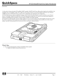
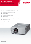
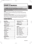
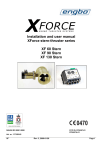
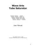
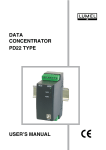
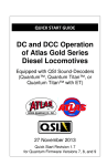
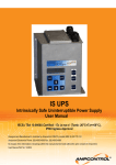
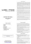
Notice
CORRECTION
PRODUCTION CHANGE
SERVICE FLASH
● ADD INFORMATION
FILE NO.
REVISION-1
Please add this notice to the Service Manual listed below.
Category :
Model :
Multi-media Projector
PLC-XF60
Issued Date :
Effective from :
December / 2004
Chassis No. MM7-XF6000
Canada, U.S./Europe,
Destination :
Asia, Africa, U.K.
REF. NO. :
SM5110680
NOTE: Match the Chassis No. on the unit’s back cover with the Chassis No. in the Service
Manual.
If the Chassis. No. does not match the unit’s, additional service literature is required.
Only the difference service information is given in this manual. For detailed service
information, refer to the original service manual SM5110680-00, issued in Novemver
2004, for Model PLC-XF60.
Outline:
This notice is to add the information about servicing when replacing the board ass'y or parts as follows;
[1] Notes on servicing Power (DC) Board and Power1 (AC) Board.
[2] Notes on servicing RS-232C Board.
FILE WITH ORIGINAL SERVICE MANUAL (SM5110680)
PRODUCT CODE
1 122 237 00 (MM7A)
1 122 238 00 (PM7A)
1 122 238 02 (PM7C)
REFERENCE NO. SM5110680-01
Electrical Parts List
[1] Notes on servicing Power (DC) Board and Power1 (AC) Board
Confirm the following description before parts order.
When replacing Power (DC) Board or Power1 (AC) Board as shown in the figure below, perform servicing according to the service description as follows;
Reason: Keep compatibility due to the Resistor Board deletion.
A001
Audio Amp. Board
A903
Power (DC) Board
Power Box
A902
Power2(AC) Board
A901
Power1(AC) Board
* There is no limtation on the servicing
for Audio Amp. Board and Power2 (AC)
Board replacement
-2-
(1) Servicing when the projector provides a Resistor Board on the Power
Box.
Do not replace Power (DC) Board or Power1 (AC) Board respectively. They must be replaced together even if other one is not defective. There are two type of Resistor Board. In each case, replace
them together.
Power Box
Resister Board
(2 pcs)
Power Box
Resister Board
(1 pce)
Service Parts List of A901[Power(DC) Board] and A903[Power1(AC) Board] Ass'y
Location
Service Code
Description
A901&A903
610 321 4825
ASSY POWER-COMP MM7A
As the supplied board assembly contains the following parts and board, replace whole the board and
parts. After replacement, the Resister Board is not necessary to install.
Power (DC) Board Assembly contains Power (DC) Board, Power Box Top Cover and Audio Amp. Board.
Power1 (AC) Board Assembly contains Power1 (AC) Board, Power Box Bottom Cover and Ventilation Fin.
-3-
(2) Servicing when the projector not provides a Resistor Board on the Power
Box.
It is enable to replace Power (DC) Board or Power1 (AC) Board independently. Place the boards as
the original.
* There is no modification on the issued service manual and parts list.
Power Box
Service Parts List of A901[Power(DC) Board] and A903[Power1(AC) Board]
Location
Service Code
Description
A901
645 068 3367
UNIT, POWER (AC)
A903
645 068 3381
UNIT, POWER (DC)
-4-
Note on mounting the Power1 (AC) Board
Mount Power1 (AC) Board Assembly as follows;
Fix ventilation fin with a hook on the power box.
Power Box
Fix ventilation fin
with a hook
Ventilation Fin
Power1(AV) Board
Top view of the Power Box
-5-
[2] Notes on servicing RS-232C Board
Due to the parts modification in the RS-232C Board, Change part number as follows. And to improve the
reliability and performance, the parts on RS-232C Board are not supplied service parts. Do not change
parts independently.
When servicing the parts in RS-232C Board, replace whole board.
Reason: To improve the reliability and performance.
A3851
RS-232C Board
Service Parts List of A3851 RS-232C Board
Location
Service Code (before)
A3851
610 314 3323
(MM7A) Dec. 2004 BB 400
state
change
Printed in Japan
Service Code (after) Description
610 321 4436
ASSY,PWB,RS232C MM7A
Inter-changibility
no
SANYO Electric Co., Ltd.