1
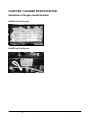
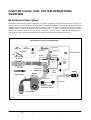
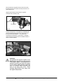
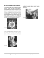
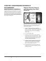
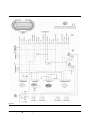
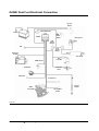
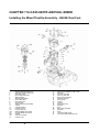
SB4192E00
Tier Dual Fuel
System (Gasoline)
G424E/G430E Tier
Lift Trucks
Dual Fuel Engine
G20E-3, G25E-3, G30E-3, G32E-3
with G424E Tier Dual Fuel Engine
G20P-3, G25P-3, G30P-3, G32P-3, G33P-3
with G430E Tier Dual Fuel Engine
Important Safety Information
Most accidents involving product operation, maintenance and repair are caused by failure to observe basic safety
rules or precautions. An accident can often be avoided by recognizing potentially hazardous situations before an
accident occurs. A person must be alert to potential hazards. This person should also have the necessary training,
skills and tools to perform these functions properly.
Read and understand all safety precautions and warnings before operating or performing lubrication,
maintenance and repair on this product.
Basic safety precautions are listed in the “Safety” section of the Service or Technical Manual. Additional safety
precautions are listed in the “Safety” section of the owner/operation/maintenance publication.
Specific safety warnings for all these publications are provided in the description of operations where hazards exist.
WARNING labels have also been put on the product to provide instructions and to identify specific hazards. If
these hazard warnings are not heeded, bodily injury or death could occur to you or other persons. Warnings in this
publication and on the product labels are identified by the following symbol.
WARNING
Improper operation, lubrication, maintenance or repair of this product can be dangerous and could result
in injury or death.
Do not operate or perform any lubrication, maintenance or repair on this product, until you have read and
understood the operation, lubrication, maintenance and repair information.
Operations that may cause product damage are identified by NOTICE labels on the product and in this publication.
DOOSAN cannot anticipate every possible circumstance that might involve a potential hazard. The warnings in
this publication and on the product are therefore not all inclusive. If a tool, procedure, work method or operating
technique not specifically recommended by DOOSAN is used, you must satisfy yourself that it is safe for you and
others. You should also ensure that the product will not be damaged or made unsafe by the operation, lubrication,
maintenance or repair procedures you choose.
The information, specifications, and illustrations in this publication are on the basis of information available at the
time it was written. The specifications, torques, pressures, measurements, adjustments, illustrations, and other
items can change at any time. These changes can affect the service given to the product. Obtain the complete and
most current information before starting any job. DOOSAN dealers have the most current information available.
1
WARNING
Read this entire manual and all other publications pertaining to the work to be performed before installing,
operating, or servicing this equipment. Practice all plant and safety instructions and precautions. Failure to follow
instructions can cause personal injury and/or property damage.
The engine or other type of prime mover should be equipped with an over speed (over temperature, or
overpressure, where applicable) shutdown device(s), that operates totally independently of the prime mover
control device(s) to protect against runaway or damage to the engine or other type of prime mover with possible
personal injury or loss of life should the mechanical-hydraulic governor(s) or electric control(s), the actuator(s), fuel
control(s), the driving mechanism(s), the linkage(s), or the controlled device(s) fail.
CAUTION
To prevent damage to a control system that uses an alternator or battery-charging device, make sure the charging
device is turned off before disconnecting the battery from the system. Electronic controls contain static-sensitive
parts. Observe the following precautions to prevent damage to these parts.
z Discharge body static before handling the control (with power to the control turned off, contact a grounded
surface and maintain contact while handling the control).
z Avoid all plastic, vinyl, and Styrofoam (except antistatic versions) around printed circuit boards.
z Do not touch the components or conductors on a printed circuit board with your hands or with conductive
devices.
IMPORTANT DEFINITIONS
WARNING—indicates a potentially hazardous situation, which, if not avoided, could result in death or
serious injury.
CAUTION—indicates a potentially hazardous situation, which, if not avoided, could result in damage to
equipment.
NOTE—provides other helpful information that does not fall under the warning or caution categories.
* This manual shows just Dual fuel Engine and engine control system for TIER- Gasoline Engine, so
regarding other ares, please refer to the separate manual of SB4136E for G424E TIER- LP Engine
and SB4137E for G430E TIER- LP Engine, and SB2215E for G424 Engine(Basic) and SB4005E for
G430 Engine(Basic).
G424E/G430E Tier
Dual Fuel Engine
2
Table of Contents
Index
CHAPTER 1 ENGINE SPECIFICATION
CHAPTER 7 N-CA55-500TR AIR/FUEL
MIXER
Indication of Engine Serial Number .................... 4
Specifications (G424E Dual Fuel Engine)........... 5
Specifications (G430E Dual Fuel Engine)........... 7
Installing the Mixer/Throttle Assembly - G424E
Dual Fuel: ........................................................28
Installing the Mixer/Throttle Assembly - G430E
Dual Fuel .........................................................29
CHAPTER 2 DUAL FUEL SYSTEM
OPERATIONAL OVERVIEW
CHAPTER 8 TEST AND ADJUSTMENTS
MI-04 General Description ................................. 9
MI-04 Dual Fuel Gasoline Delivery System ...... 11
MI-04 Gasoline Fuel Injection........................... 13
Testing the Gasoline Fuel Delivery System.......31
Timing Adjustment - G424E LP and Dual Fuel
Engine .............................................................34
Ignition Timing Adjustment ...............................34
Timing Adjustment - G430E Dual Fuel Engine ..37
Idle Mixture Adjustment ....................................40
CHAPTER 3 MAINTENANCE
SCHEDULE
RECOMMENDED MAINTENANCE SCHEDULE14
Replace Gasoline Primary and Secondary Fuel
Filter Elements................................................. 14
Inspect the Fuel Pump Insulated Mounting Clamps
........................................................................ 15
Maintenance Schedule..................................... 15
CHAPTER 9 SERVICE TOOL KIT
CHAPTER 4 BASIC
TROUBLESHOOTING
Basic Troubleshooting (Gasoline)..................... 16
CHAPTER 5 MI-04 ADVANCED
DIAGNOSTICS
Fault List Definitions......................................... 21
Table a. MI-04 Diagnostic Fault Codes (Flash
Codes)............................................................. 22
CHAPTER 6 ELECTRICAL
CONNECTIONS
G424E Dual Fuel Electrical Connection............ 23
G430E Dual Fuel Electrical Connection............ 25
Resistance Checks .......................................... 27
G424E/G430E Tier
Dual Fuel Engine
3
Table of Contents
CHAPTER 1 ENGINE SPECIFICATION
Indication of Engine Serial Number
G424E Dual Fuel Engine
G430E Dual Fuel Engine
G424E/G430E Tier
Dual Fuel Engine
4
Engine Specification
Specifications (G424E Dual Fuel Engine)
GENERAL DESCRIPTION
ENGINE TYPE:
COMBUSTION SYSTEM:
EXHAUST SYSTEM:
VALVE CONFIGURATION:
DISPLACEMENT:
BORE:
STROKE:
COMPRESSION RATIO:
COMPRESSION PRESSURE:
VALVE TIMING:
FIRING ORDER:
SPARK PLUGS:
WEIGHT:
ROTATION:
FUELTYPE:
GOVERNED SPEED:
IDLE RPM:
IGNITIOIN TIMING:
Water-cooled, Inline 4-Cycle, 4-Cylinders
Naturally Aspirated 1-Venturi Intake Manifold
Semi-spherical Combustion chamber
Cast Iron, Dry
OHC, 2 Valves per Cylinder
2,350 cc (143 CID)
86.5 mm (3.41 in.)
100 mm (3.94 in.)
8.6:1
1,128 kPa (163.5 psi)
Intake Valve: 12° BTDC(Open)/ 40° ABDC(Close)
Exhaust Valve: 54° BBDC(Open)/ 6° ATDC(Close)
1-3-4-2
BPR5ES: 0.7-0.8 mm (0.028-0.031 in.) Air Gap
146 Kg (322 lbs.), Dry
Counter-Clockwise (CCW) when viewed from Flywheel End
LPG/Gasoline
2600 +/- 25 RPM
700 +/- 25 RPM for LPG
750 +/- 25 RPM for Gasoline
Electronic controlled by ECM
LP FUEL SYSTEM
MIXER:
REGULATOR:
FUEL FILTRATION:
Piston Type Air Valve Assembly inside, Downdraft
Two-Stage Negative Pressure Regulator
40 Microns Maximum
GASOLINE FUEL SYSTEM
FUEL FILTER-PRIMARY
FUEL PUMP
FUEL FILTER-SECONDARY
GASOLINE REGULATOR ASM
FUEL INJECTOR ASS’Y
60 Microns
Electric Fuel Pump (12V)
10 Microns
Gasoline Pressure Regulator (270kPa)
Electric Fuel Injector (12V)
COOLING SYSTEM
WATER PUMP ROTATION:
THERMOSTAT:
COOLING WATER CAPACITY:
V-Belt Drive - Clockwise (CW) when viewed from engine front
Opening Temperature: 82°C (180°F)
Fully Open Temperature: 95°C (203°F)
3.1 L (block only)
LUBRICATION SYSTEM
OIL PRESSURE:
OIL TEMPERATURE:
CRANKCASE CAPACITY:
OIL FILTER:
ENGINE OIL SPECIFICATION:
50 kPa (7 psi) @ Low Idle 450 kPa (65 psi) @ Hi Idle
Upper Limit:
125°C (257°F)
Recommended:
99 - 110°C (210 - 230°F)
Lower Limit:
80°C (176°F)
3.7 L
0.3 L
API - SJ, SAE 10W30 or SAE 5W30
ENGINE ELECTRICAL
IGNITION TYPE:
IGNITION COIL:
DISTRIBUTOR:
STARTER MOTOR:
ALTERNATOR:
ENGINE OIL PR. S/W:
ENGINE CONTROL MODULE(ECM):
VR SENSOR:
TMAP:
PEDAL ANGLE SENSOR:
OXYGEN SENSOR:
ECT-ECM:
ECT-GAUGE
TPS:
G424E/G430E Tier
Dual Fuel Engine
Electronic Advanced by ECM
12 V operation volt, Ignition driver circuitry inside
Mitsubishi Distributor
12 Volt, 1.2 kW, Reduction drive
12 Volt, 61 Amp
24.5 kPa (3.6 psi)
12 V operation volt, 24 pins of I/O
Magnetic pick up sensor(assembled on Timing belt cover)
Intake Air Temp. & Manifold Absolute Press. Sensor
Two-Output Signals (Installed on Accelerator Pedal)
Heated Exhaust Gas Oxygen Sensor (HEGO) 12 V operation volt
Engine Coolant Temperature Sensor for ECM
Engine Coolant Temp. Sensor for GAUGE on Instrument Panel
Throttle Position Sensor (built in Throttle Body)
5
Engine Specification
THROTTLE BODY:
FUEL TRIM VALVE (FTV):
LP FUEL LOCK-OFF:
Electronic Throttle Body
12 V operation volt
12 V operation volt, ON/OFF Control by ECM
EXHAUST SYSTEM
CATALYTIC MUFFLER:
G424E/G430E Tier
Three-way Catalyst included
Dual Fuel Engine
6
Engine Specification
Specifications (G430E Dual Fuel Engine)
GENERAL DESCRIPTION
ENGINE TYPE:
COMBUSTION SYSTEM:
EXHAUST SYSTEM:
VALVE CONFIGURATION:
DISPLACEMENT:
BORE:
STROKE:
COMPRESSION RATIO:
COMPRESSION PRESSURE:
FIRING ORDER:
SPARK PLUGS:
WEIGHT:
Water-cooled, Inline 4-Cycle, 4-Cylinders
Naturally Aspirated 1-Venturi Intake Manifold
Cast Iron, Dry
Pushrod Actuated Overhead Valves - 2 Per Cylinder
2.967 cc (181 CID)
101.60 mm (4.00 in.)
91.44 mm (3.60 in.)
9.25:1
690 kPa (100 psi) Minimum
1-3-4-2
AC R46TS - 0.9 mm (0.035 in.) Air Gap
165 Kg (363 lbs.), Dry
Counter-Clockwise (CCW) when viewed from Flywheel
End
LPG/Gasoline
2500 +/- 25 RPM
700 +/- 25 RPM for LPG,
750 +/- 25 RPM for Gasoline
Electronic controlled by ECM
ROTATION:
FUELTYPE:
GOVERNED SPEED:
IDLE RPM:
IGNITIOIN TIMING:
LP FUEL SYSTEM
MIXER:
REGULATOR:
FUEL FILTRATION:
GASOLINE FUEL SYSTEM
Piston Type Air Valve Assembly inside, Downdraft
Two-Stage Negative Pressure Regulator
40 Microns Maximum
FUEL FILTER - PRIMARY
ELECTRIC FUEL PUMP
FUEL FILTER - SECONDARY
GASOLINE REGULATOR ASM
FUEL INJECTOR ASS’Y
60 Micron
Electric Fuel Pump (12V)
10 Micron
Gasoline Pressure Regulator (270kPa)
Electric Fuel Injector (12V)
COOLING SYSTEM
V-Belt Drive - Clockwise (CW) when viewed from
engine front
Opening Temperature: 82°C (180°F)
Fully Open Temperature: 96°C (205°F)
3.8 L (block only)
WATER PUMP ROTATION:
THERMOSTAT:
COOLING WATER CAPACITY:
LUBRICATION SYSTEM
28 kPa (4 psi) @ 700 RPM
124 kPa (18 psi) @ 2000 RPM
Upper Limit:
130°C (266°F)
Recommended:
99 - 110°C (210 - 230°F)
Lower Limit:
80°C (176°F)
3.8 L (4.0 qts.)
0.95 L (1 qt.)
API - SJ, SAE 10W30
OIL PRESSURE (MIN. HOT):
OIL TEMPERATURE:
CRANKCASE CAPACITY:
OIL FILTER:
ENGINE OIL SPECIFICATION:
ENGINE ELECTRICAL
IGNITION TYPE:
IGNITION COIL:
DISTRIBUTOR:
STARTER MOTOR:
ALTERNATOR:
ENGINE OIL PR. S/W:
ENGINE CONTROL MODULE(ECM):
Electronic Advanced by ECM
12 V operation volt
Delco EST Distributor with ignition module
12 Volt, 2.0 kW
12 Volt, 61 Amp
21.4 kPa (3.1 psi)
12 V operation volt, 24 pins of I/O
Magnetic pick up sensor(assembled on Flywheel
Housing)
Intake Air Temp. & Manifold Absolute Press. Sensor
Installed on Accelerator Pedal
Heated Exhaust Gas Oxygen Sensor (HEGO)
12 V operation volt
Engine Coolant Temperature Sensor for ECM
VR SENSOR:
TMAP:
PEDAL ANGLE SENSOR:
OXYGEN SENSOR:
ECT-ECM:
G424E/G430E Tier
Dual Fuel Engine
7
Engine Specification
Engine Coolant Temp. Sensor for GAUGE on
Instrument Panel
Throttle Position Sensor (built in Throttle Body)
Electronic Throttle Body
12 V operation volt
12 V operation volt, ON/OFF Control by ECM
ECT-GAUGE
TPS:
THROTTLE BODY:
FUEL TRIM VALVE (FTV):
LP FUEL LOCK-OFF:
EXHAUST SYSTEM
CATALYTIC MUFFLER:
G424E/G430E Tier
Dual Fuel Engine
Three-way Catalyst included
8
Engine Specification
CHAPTER 2 DUAL FUEL SYSTEM OPERATIONAL
OVERVIEW
MI-04 General Description
Woodward’s MI-04 control system is designed to provide a complete, fully integrated solution that will meet or
exceed TIER-2 Large Spark Ignited Engines emission standards established by the California Air Research Board
(CARB) and the Environmental Protection Agency (EPA) for 2004. The MI-04 is a closed loop system utilizing a
catalytic muffler to reduce the emission level in the exhaust gas. In order to obtain maximum effect from the
catalyst, an accurate control of the air fuel ratio is required. A small engine control module (SECM) uses a
heated exhaust gas oxygen sensor (HEGO) in the exhaust system to monitor exhaust gas content.
MI-04 Dual Fuel System of G424E Engine
LP Fuel Line
Fault Light
Key switch
Foot Pedal
APP
Main
PWR
Relay
LP Fuel Filter
Fuel Lock
Fuel Select Switch
Converter
Vacuum
Air Cleaner
Coolant Line
Fuel Trim
Valve
2
Fuel
Select
Relay
1&2
Mixer
Fuel Pump
Fuel Injector
DBW Throttle
TPS
TMAP
Engine
1
SECM
Oxygen Sensor
Distributor
Smart Coil
VR Sensor
Oil Pressure Switch
Coolant Temp Sensor
Catalytic Muffler
Figure 10
G424E/G430E Tier
Dual Fuel Engine
9
System Operational Overview
The SECM makes any necessary corrections to the air fuel ratio by controlling the inlet fuel pressure to the air/fuel
mixer by modulating the fuel trim valve (FTV) connected to the regulator. Reducing the fuel pressure leans the
air/fuel mixture and increasing the fuel pressure enriches the air/fuel mixture. To calculate any necessary
corrections to the air fuel ratio, the SECM uses a number of different sensors to gain information about the engines
performance. Engine speed is monitored by the SECM through a variable reluctance (VR) sensor. Intake
manifold air temperature and absolute pressure is monitored with a (TMAP) sensor. The MI-04 is a drive by wire
(DBW) system connecting the accelerator pedal to the electronic throttle through the electrical harness;
mechanical cables are not used. A throttle position sensor (TPS) monitors throttle position in relation to the
accelerator pedal position sensor (APP) feedback. Even engine coolant temperature and adequate oil pressure
is monitored by the SECM. The SECM controller has full adaptive learning capabilities, allowing it to adapt
control function as operating conditions change. Factors such as ambient temperature, fuel variations, ignition
component wear, clogged air filter, and other operating variables are compensated.
MI-04 Dual Fuel System of G430E Engine
Fault Light
LP Fuel Line
Key switch
Foot Pedal
APP
LP Fuel Filter
Main
PWR
Relay
Fuel Lock
Fuel Select
Converter
Vacuum
Air Cleaner
Coolant Line
Fuel Trim
Valve
2
Mixer
Fuel Pump
Fuel
Select
Relay
1&2
Fuel Injector
DBW Throttle
TPS
TMAP
1
SECM
Oxygen Sensor
Distributor
VR Sensor
Oil Pressure Switch
Coolant Temp Sensor
Engine
Catalytic Muffler
Figure 10
G424E/G430E Tier
Dual Fuel Engine
10
System Operational Overview
The pump discharge is located on the electrical
terminal side of the pump. Both fuel filters and fuel
pump have a specific inlet orientation to fuel flow,
which should be noted upon installation.
MI-04 Dual Fuel Gasoline
Delivery System
A manual fuel select switch enables the forklift
operator to choose between LPG or Gasoline
operation. When the select switch is in the Gasoline
position an electric fuel pump supplies the fuel and
generates the injection pressure.
The fuel is
pumped through a Primary 60 micron filter to the
pump (Figure 23). The pump then discharges the fuel
at an increased pressure through a Secondary 10
micron filter to a pressure regulator. The pressure
regulator incorporates a spring-loaded diaphragm
with no bias signal connected, maintaining a constant
operating fuel pressure at the metering orifice (270
Kpa) regardless of the amount of fuel being injected.
The electric fuel pump incorporates a G-Rotor
pumping element driven by an electric motor with
permanent magnets, an internal check valve to
prevent back flow and is mounted external from the
fuel tank.
Secondary
Fuel Filter
Figure 24
Fuel Select Switch
Secondary
Gasoline
Filter
Flow
Electric Fuel
Pump
Primary
Gasoline Filter
Electric Fuel Pump
*Mounting locations shown are specific to
G20/25/30E-3 model.
G424E/G430E Tier
Dual Fuel Engine
11
System Operational Overview
The fuel pressure regulator returns fuel to the tank
through the return line when the fuel pressure is too
great. (Figure 25)
(Figure 26) shows the fuel pressure regulator
mounted near the battery tray.
Tank Return
Line
Fuel Outlet
Fuel Inlet
Figure 25
A single fuel injector is controlled by the SECM and
when energized meters fuel before the throttle into
the mixer to throttle adapter. For proper fuel
atomization and delivery to the throttle, a separate
venturi booster section has been installed inside the
mixer to throttle adapter.
Figure 26
WARNING
The gasoline fuel injection system of the
MI-04 system operates at a fuel pressure
of 270 Kpa (~39psi). Pressurized fuel is
present in the fuel lines when the engine
is not running. Safety glasses should be
worn at all times when removing fuel
lines or eye injury may occur! Avoid
directing high-pressure fuel spray onto
hot engine components!.
G424E/G430E Tier
Dual Fuel Engine
12
System Operational Overview
MI-04 Gasoline Fuel Injection
In (Figure 29) the fuel injector is shown out of the
throttle body adapter. A spacer is used on the tip of
the injector to properly seat the injector with the
venturi o-ring.
A single Seimens high flow fuel injector is used to
inject fuel into the LPG mixer to throttle adapter.
Intake air to the engine continues to flow through the
LPG mixer however propane is not supplied to the
mixer while in gasoline operation. A booster venturi
(Figure 27) inside the adapter receives the fuel from
the injector and distributes it into the air stream before
the throttle valve. The VR signal from the 30-5
timing wheel located on the crankshaft pulley is used
by the SECM as an engine position reference for
correct operation of the injector. The SECM uses
the measured air-fuel ratio from the oxygen sensor to
control the amount of fuel delivered by the injector.
Figure 29
Figure 27
A view of a separate injector venturi used in a twopiece throttle adapter is shown in (Figure 28) for a
clearer description. The MI-04 dual fuel throttle
adapter uses a single piece adapter where the venturi
cannot be removed.
Figure 28
G424E/G430E Tier
Dual Fuel Engine
13
System Operational Overview
CHAPTER 3 MAINTENANCE SCHEDULE
RECOMMENDED
MAINTENANCE SCHEDULE
Replace Gasoline Primary
and Secondary Fuel Filter
Elements
Suggested maintenance requirements for an engine
equipped with an MI-04 fuel system are contained in
this section. The owner should, however, develop his
own maintenance schedule using the requirements
listed in this section and any other requirements listed
by the engine manufacturer..
Secondary
Gasoline
Filter
Flow
Electric Fuel
Pump
Primary
Gasoline Filter
Park the lift truck in an authorized refueling area with
the forks lowered, parking brake applied and the
transmission in Neutral.
1. Place the fuel select switch in the Gasoline
position. Remove the fuel select relay #2 for the
electric fuel pump. Start and run the engine until
the fuel in the system runs out of fuel and the
engine stops.
2. Turn off the ignition switch.
3. Replace the fuel filter taking care to install the
new filter with flow in the proper direction. When
replacing the Primary fuel filter use a hose clamp
between the tank and the filter to prevent fuel
from spilling during replacement.
4. Prefilling the primary gasoline filter with fuel will
greatly reduce the cranking time necessary to
prime the pump anytime the primary gasoline
filter or pump is drained for service.
5. Re-install the fuse for the pump and crank the
engine several times before attempting a start to
prime the fuel pump.
G424E/G430E Tier
Dual Fuel Engine
14
System Operational Overview
Inspect the Fuel Pump Insulated Mounting Clamps
•
•
•
•
•
Turn the ignition key to the ON position (without cranking the engine), you should hear the electric fuel pump
running.
After 5 seconds the pump should stop running.
If the pump continues to run check the rubber insulation on the electric fuel pump mounting clamps.
If the housing of the pump makes contact with the engine chassis a ground path can be created causing the
pump to run anytime the ignition key is in the ON position and the fuel select switch is in GAS position, causing
pre-mature pump failure.
If the clamp insulation is damaged replace the clamp with a new insulated clamp.
Maintenance Schedule
Interval Hours
CHECK POINT
Daily
Every
250hrs or
a month
Every 500
Hours or
3 months
Every
1000
Hours or
6 months
Every
1500
Hours or
9 months
Every
2500
Hours or
15 months
Every
4000
Hours
or 2
years
Fuel Lock-Off/Fuel Filter Section (LPG & Gasoline)
Replace Primary Gasoline
fuel filter
Replace Secondary
Gasoline fuel filter
Inspect fuel pump
insulated retaining clamps
G424E/G430E Tier
Dual Fuel Engine
X
X
X
15
System Operational Overview
CHAPTER 4 BASIC TROUBLESHOOTING
Basic Troubleshooting (Gasoline)
The MI-04 systems are equipped with built-in fault diagnostics. Detected system faults can be displayed by the
Malfunction Indicator Lamp (MIL) and are covered in the Advanced Diagnostics section. Items such as fuel level,
plugged fuel lines, clogged fuel filters and malfunctioning pressure regulators may not set a fault code by the Small
Engine Control Module (SECM). Below are basic checks that should be made before referring to the Advanced
Diagnostics section, if engine or drivability problems are encountered.
Consider all parts of the ignition and mechanical systems as well as the fuel system.
Problem
Probable Cause
Engine Cranking
but Will Not Start
(Gas)
G424E/G430E Tier
Corrective Action
Fuel tank empty
Fill fuel container
z The tank should be at least ¼ full to properly
prime the fuel pump.
z Fuel select switch is not on GAS
Clogged fuel filter
Repair/replace as required
z See Primary and Secondary Fuel Filter
replacement
Improper fuel supply line
connection between the tank
and the fuel pump
Check connection
z Verify correct hose connections
z Clamps must be tight
z Look for kinked, pinched and/or collapsed
hose
Electric Fuel Pump malfunction
(GAS)
Check electrical connection
z Check Relay and fuse
Turn key ON and verify pump is operating
Fuel Pressure regulator
malfunction
Test pressure regulator operation
z See Tests and Adjustments
Fuel Injector malfunction
Test Injector operation
z See Tests and Adjustments
Incorrect air/fuel or
ignition/spark control
See Advanced Diagnostics
No VR Sensor Signal
Verify the VR signal is present
z See Advanced Diagnostics
Dual Fuel Engine
16
Basic Troubleshooting
Problem
Difficult to Start
(Gas)
Will Not Run
Continuously
(Gas)
Probable Cause
Corrective Action
Fuel tank almost empty
Fuel Pump Cavitations
z The tank should be at least ¼ full to properly
prime the fuel pump
z Fuel select switch is not on GAS
Clogged fuel filter
Repair/replace as required
z See Primary and Secondary Fuel Filter
replacement
Electric Fuel Pump malfunction
(GAS)
Check electrical connection
z Check Relay and fuse Turn key ON and verify
pump is operating
z See Tests and Adjustments
Pressure regulator malfunction
Test pressure regulator operation
z See Tests and Adjustments
Fuel Injector malfunction
Test Injector operation
z See Tests and Adjustments
Air filter clogged
Check air filter
z Clean/replace as required
Incorrect air/fuel or ignition
control
See Advanced Diagnostics
Engine Mechanical
See Engine Manufacturers Service Manual
Isolate the gasoline system by
running the lift truck on LPG
Verify LPG cylinder is full and valve is open. If
the problem does not exist in LPG mode proceed
with the corrective action steps below.
If the problem also exists in LPG mode then the
root cause is most likely to be something other
than the fuel system
z See Advanced Diagnostics
G424E/G430E Tier
Fuel tank almost empty
Fuel Pump Cavitations
z The tank should be at least ¼ full to properly
prime the fuel pump
Clogged fuel filter
Repair/replace as required
z See Primary and Secondary Fuel Filter
replacement
Dual Fuel Engine
17
Basic Troubleshooting
Problem
Probable Cause
Will Not Run
Continuously (Gas)
Will Not
Accelerate/Hesitation
During Acceleration or
Engine Stalls (Gas)
Corrective Action
Electric Fuel Pump
malfunction (GAS)
Check electrical connection
z Check Relay and fuse Turn key ON and
verify pump is operating
z See Tests and Adjustments
Pressure regulator
malfunction
Test pressure regulator operation
z See Tests and Adjustments
Fuel Injector malfunction
Test Injector operation
z See Tests and Adjustments
Incorrect idle speed or
ignition problem
See Advanced Diagnostics
Engine Mechanical
See Engine Manufacturers Service Manual
Isolate the gasoline system
by running the lift truck on
LPG
Verify LPG cylinder is full and valve is open.
If the problem does not exist in LPG mode
proceed with the corrective action steps
below.
If the problem also exists in LPG mode then
the root cause is most likely to be something
other than the fuel system
z See Advanced Diagnostics
G424E/G430E Tier
Fuel tank almost empty
Fuel Pump Cavitations
z The tank should be at least ¼ full to
properly prime the fuel pump
Clogged fuel filter
Repair/replace as required
z See Primary and Secondary Fuel Filter
replacement
Pressure regulator
malfunction
Test pressure regulator operation
z See Tests and Adjustments
Fuel Injector malfunction
Test Injector operation
z See Tests and Adjustments
Dual Fuel Engine
18
Basic Troubleshooting
Problem
Probable Cause
Will Not
Accelerate/Hesitation
During Acceleration or
Engine Stalls (Gas)
Throttle butterfly valve not
opening or sticking
Corrective Action
See Advanced Diagnostics
Foot Pedal signal incorrect
or intermittent
Incorrect air/fuel or ignition
control
Rough Idle (Gas)
Engine Mechanical
See Engine Manufacturers Service Manual
Isolate the gasoline system
by running the lift truck on
LPG
Verify LPG cylinder is full and valve is open.
If the problem does not exist in LPG mode
proceed with the corrective action steps
below.
If the problem also exists in LPG mode then
the root cause is most likely to be something
other than the fuel system
z See Advanced Diagnostics & Tests and
Adjustments
G424E/G430E Tier
Pressure regulator
malfunction
Test pressure regulator operation
z See Tests and Adjustments
Clogged fuel filter
Repair/replace as required
z See Primary and Secondary Fuel Filter
replacement
Pressure regulator
malfunction
Test pressure regulator operation
z See Tests and Adjustments
Fuel Injector malfunction
Test Injector operation
z See Tests and Adjustments
Vacuum leak
Check for vacuum leaks
z Between mixer and throttle body
z Between throttle body and intake manifold
z Between intake manifold and cylinder
head
Dual Fuel Engine
19
Basic Troubleshooting
Problem
Probable Cause
Rough Idle (Gas)
Incorrect Idle speed control
Incorrect timing or spark
control
High Idle Speed
(Gas)
Corrective Action
See Advanced Diagnostics & Tests and
Adjustments
Engine Mechanical
See Engine Manufacturers Service Manual
Incorrect Idle speed control
See Advanced Diagnostics & Tests and
Adjustments
Throttle sticking
Poor High Speed
Performance (Gas)
Foot pedal sticking or
incorrect pedal signal
Check pedal return spring travel for binding See
Advanced Diagnostics
Isolate the gasoline system by
running the lift truck on LPG
Verify LPG cylinder is full and valve is open. If
the problem does not exist in LPG mode
proceed with the corrective action steps below.
If the problem also exists in LPG mode then the
root cause is most likely to be something other
than the fuel system
z See Advanced Diagnostics & Tests and
Adjustments
Poor High Speed
Performance (Gas)
Clogged fuel filter
Repair/replace as required
z See Fuel Filter replacement
Plugged fuel line
Remove obstruction from the fuel line
z Close liquid fuel valve
z Using caution, disconnect the fuel line (some
propane may escape)
z Clear obstruction with compressed air
z Re-connect fuel line
z Slowly open liquid fuel valve & Leak test
Air filter clogged
Check air filter
z Clean/replace as required
Faulty vapor connection
between the pressure
regulator/converter and the
mixer
Check connection
z Verify no holes in hose
z Clamps must be tight
z Look for kinked, pinched and/or collapsed
hose
Pressure regulator
malfunction
Test pressure regulator operation
z See Tests and Adjustments
Air/Fuel Mixer malfunction
Check mixer
z See Air/Fuel mixer section
Restricted exhaust system
Check exhaust system
z Measure exhaust back pressure
Incorrect ignition control
See Advanced Diagnostics & Tests and
Adjustments
Incorrect air/fuel control
Incorrect throttle position
G424E/G430E Tier
Dual Fuel Engine
20
Basic Troubleshooting
CHAPTER 5 MI-04 ADVANCED DIAGNOSTICS
Fault List Definitions
Several sensors in the MI-04 system have input
low/high faults and a sensor range fault. These are
the coolant temperature sensor, the throttle position
sensor and the pedal position sensors. Signals to
these sensors are converted into digital counts by the
SECM. A low/high sensor fault is normal set when the
converted digital counts reach the minimum of 0 or
the maximum of 1024 (1024=5.0 VDC with ~204
counts per volt). A sensor range fault is set if the
parameter measured by the sensor is outside the
normal operating range.
1024 Counts (Input High)
Sensor Range
0 Counts (Input Low)
Figure F1
Injector Fault: (Fuel Injector Fault) is normally set
when the injector driver signal is open due to the
connector becoming disconnected.
Low Oil Pressure: (Low Oil Pressure) the oil
pressure switch has closed or become failed,
normally indicating a low oil condition in the engine.
G424E/G430E Tier
Dual Fuel Engine
21
Advanced Diagnostics
Table a. MI-04 Diagnostic Fault Codes (Flash Codes)
DFC
51
Probable Fault
Injector Fault
Action
Stored Fault Code
(MIL, Disable
Adaptive learns)
Corrective Action, First Check
Check Injector (INJ) for an open wire or
injector connector being disconnected
INJ PIN A (SIGNAL) TO PIN B (PWR)
Check INJ for an open coil by
disconnecting the INJ connector and
measuring the coil resistance (~12Ω +/2Ω)
INJ PIN A (SIGNAL) TO PIN B (PWR)
52
Low Oil Pressure
Low Engine Oil Pressure
Delayed Engine
Shutdown
Check engine oil level
Check electrical connection to the oil
pressure switch
SECM PIN 23 to Oil Pressure Switch
31
Running Reset
Stored Fault Code
Reset Counter to be
incremented
Check to ensure that proper grounding of
the harnessing has been achieved.
Check to ensure that there are no
intermittent connections in the electrical
harness or associated connections.
Check for interruptions in Vbatt supply to
the SECM.
Check to ensure that the ignition system
(distributor, coil, cap, rotor, plugs, and high
tension leads) is operating normally.
G424E/G430E Tier
Dual Fuel Engine
22
Advanced Diagnostics
CHAPTER 6 ELECTRICAL CONNECTIONS
G424E Dual Fuel Electrical Connection
Ignition
Switch
Main PWR Relay
Battery
SECM
Fuel
Select
Switch
Fuel
Select
Relay 2
Fuel Injector
MIL
Fuel
Select
Relay 1
Electronic
Throttle
Fuel Pump
Fuel
Lock-Off
TMAP Sensor
Fuel Trim
Valve
Smart Coil
VR Sensor
ECT Sensor
DBW
Foot Pedal
Oil Pressure
Switch
Oxygen
Sensor
Figure E1
G424E/G430E Tier
Dual Fuel Engine
23
Electrical Connections
Figure E2
G424E/G430E Tier
Dual Fuel Engine
24
Electrical Connections
G430E Dual Fuel Electrical Connection
Ignition
Switch
Main PWR Relay
Battery
Fuel
Select
Switch
SECM
Fuel Injector
Fuel
Select
Relay 2
MIL
Fuel
Select
Relay 1
Electronic
Throttle
Fuel Pump
Fuel
Lock-Off
TMAP Sensor
Distributor
Fuel Trim
Valve
VR Sensor
ECT Sensor
Oxygen
Sensor
DBW
Foot Pedal
Oil Pressure
Switch
Figure E1
G424E/G430E Tier
Dual Fuel Engine
25
Electrical Connections
Figure E2
G424E/G430E Tier
Dual Fuel Engine
26
Electrical Connections
Resistance Checks
NOTE
All resistive checks are made with the sensor or device disconnected from the harness.
CONNECTOR
INJ (FUEL INJECTOR)
POINT TO POINT
INJ PIN A (SIGNAL) TO PIN B
(PWR)
CONNECTOR
FUEL PUMP (GAS)
POINT TO POINT
PUMP HOUSING TO CHASSIS
CONNECTOR
VR SENSOR
G424E/G430E Tier
POINT TO POINT
VR PIN 1 (+) TO PIN 2 (-)
Dual Fuel Engine
27
EXPECTED RANGE
(~12Ω +/-2Ω)
EXPECTED RANGE
(0Ω)*Pump housing should be
isolated from chassis ground
EXPECTED RANGE
~320Ω
Electrical Connections
CHAPTER 7 N-CA55-500TR AIR/FUEL MIXER
Installing the Mixer/Throttle Assembly - G424E Dual Fuel:
1
2
3
4
5
6
7
8
9
10
11
12
13
13A
13B
13C
13D
13E
14
15
17
18
19
20
21
22
23
24
25
26
27
28
29
30
31
32
GASKET-INTAKE MANIFOLD
ADAPTER-INTAKE MANIFOLD
BRACKET-TMAP
BOLT-TMAP BRACKET
TMAP SENSOR
WASHER-TMAP MTG
BOLT-TMAP MTG
BOLT-ADAPTER
GASKET-ITB
THROTTLE BODY(ITB 32MM)
O-RING
O-RING SPACER
LP MIXER(CA55)
FITTING-ORIFICE
GASKET-MIXER,AIR HORN
GASKET-MIXER,ADAPTER
SCREW
CAP-IDLE SCREW
FITTING-FUEL
G424E/G430E Tier
Dual Fuel Engine
28
INJECTOR ASSEMBLY FUEL HOSE
VENTURI
VENTURI SPACER
APOLLO ADAPTER
BOLT-INJECTOR MTG
WASHER-SPRING
SET SCREW
O-RING
FITTING
BOLT-END PLUG
WASHER
BOLT
AIR HORN ADAPTER
WASHER
BOLT
FITTING-VENTILATION
COOLANT TEMP SENSOR-ECM
N-CA55-500TR Mixer
Installing the Mixer/Throttle Assembly - G430E Dual Fuel
1
2
3
4
5
6
7
8
9
10
11
12
13
14
15
15A
15B
15C
15D
15E
16
17
17A
18
19
20
21
22
23
24
25
26
27
28
29
30
31
32
33
34
GASKET-INTAKE MANIFOLD
ADAPTER-INTAKEMANIFOLD
BRACKET-TMAP
BOLT-TMAP BRACKET
FITTING-OUTLET
FITTING-INLET
TMAP
WASHER-TMAP MTG
BOLT-TMAP MTG
BOLT-ADAPTER
GASKET-ITB
THROTTLE BODY
O-RING
O-RING SPACER
MIXER
FITTING-ORIFICE
GASKET-MIXER,AIR HORN
GASKET-MIXER,ADAPTER
SCREW
CAP-IDLE SCREW
FITTING-TO CONVERTER INLET
G424E/G430E Tier
Dual Fuel Engine
29
INJECTOR ASSEMBLY
FUEL HOSE
VENTURI
VENTURI SPACER
APOLLO ADAPTER FOR DUAL FUEL
BOLT-INJECTOR MTG
WASHER
SET SCREW
O-RING
FITTING-TO TRIM V/V
BOLT-END PLUG
BOLT-ITB.CONN
AIR-HORN ADAPTER
WASHER-AIR HORN
BOLT-AIR HORN
PLUG
HOSE-COOLANT(FORMED)
CLAMP-HOSE(WATER PUMP)
CLAMP-HOSE(FITTING)
N-CA55-500TR Mixer
CHAPTER 8 TEST AND ADJUSTMENTS
WARNING
z
z
z
LP gas is highly flammable. To prevent
personal injury, keep fire and flammable
materials away from the lift truck when work
is done on the fuel system.
Gas vapor may reduce oxygen available for
breathing, cause headache, nausea,
dizziness and unconsciousness and lead to
injury or death. Always operate the forklift in
a well ventilated area
Liquid propane may cause freezing of tissue
or frostbite. Avoid direct contact with skin or
tissue; always wear appropriate safety
protection including gloves and safety
glasses when working with liquid propane.
CAUTION
The regulator/converter and mixer are
part of a certified system complying with
EPA and CARB 2004 requirements. Only
trained certified technicians should
perform disassemble, service or
replacement of the regulator/converter or
mixer.
G424E/G430E Tier
Dual Fuel Engine
30
TEST AND ADJUSTMENTS
Testing the Gasoline Fuel Delivery System
Gasoline System Test Hardware
1. Universal 278000 Noid “test” light
2. Pinch-off pliers, hose clamp or Vise-Grip type pliers
3. Small fuel “catch” container.
Operating fuel pressure of the gasoline system is 270 Kpa (~39 psi). At least ¼ of the fuel tank should be filled
with fuel to provide a proper fuel prime from the tank “pick-up” tube to the fuel pump, anything less may cause the
pump to cavitate allowing air into the fuel system. A primary 100-micron fuel filter is used inline before the electric
fuel pump and a 10-micron secondary fuel filter is used between the fuel pump and the fuel pressure regulator.
The regulator does not use a bias control signal on the diaphragm and always supplies a constant pressure.
When fuel pressure is too high the regulator routes excessive fuel through the return line back to the fuel tank.
Regulated fuel pressure is supplied from the regulator outlet exits to the fuel injector. The fuel lines from the fuel
pump to the injector are under pressure even when the engine is not running and care should be taken when
disconnecting these fuel lines, as pressurized fuel will be discharged.
Fuel Tank Outlet
st
1 Filter to Pump
nd
Pump to 2
Filter
Regulator Inlet
Return to Tank
Fuel Tank Outlet
Figure F1
NOTE
Pump, filter and regulator mounting locations as shown are specific to G20/25/30E-3 lift trucks
G424E/G430E Tier
Dual Fuel Engine
31
TEST AND ADJUSTMENTS
The return line from the regulator to the fuel tank is
not under pressure and can safely be removed
without pressurized fuel spray.
To check for SECM signal pulses to the fuel injector
simply disconnect the electrical harness from the fuel
injector and connect the Noid test light to the end of
the harness in place of the injector. Crank the
engine with the ignition key and you will see the Noid
light flash every time the SECM sends a signal to the
fuel injector to open and spray fuel. If SECM pulses
are not present at the injector and a DFC code 51
(Injector Fault) has not been set, the Fuel Select
Relay #1 may be at fault.
Verify that the Fuel Selector Switch is in the Gasoline
position before performing the following tests. A fuel
pressure tap is not provided in the MI04 gasoline
system.
In order to check the operating fuel pressure of the
system a pressure gauge and T fitting must be
installed before the pressure regulator to measure
fuel pump supplied pressure or after the pressure
regulator to measure regulated pressure.
When the Fuel Select Switch is placed in the Gas
position a low or ground signal is supplied through the
switch to PIN 8 of the SECM. This ground signal
informs the SECM that the lift truck should operate in
Gasoline mode. When the SECM PIN 8 input is
“low”, the SECM PIN 21 output becomes “low”
supplying the ground signal to the coil of both the #1
and #2 Fuel Select Relays. Voltage (+12 VDC) is
supplied to one side of the coil for both the #1 and #2
Fuel Select Relays when the key switch is in the ON
position. When the #1 Fuel Select Relay coil is
energized the relay will switch SECM PIN 12 output
from the FTV to the fuel injector. The SECM PIN 12
output signal supplies the fuel injector with the correct
drive pulses.
WARNING
The gasoline fuel injection system of the
MI-04 system operates at a fuel pressure
of 270 Kpa (~39psi). Pressurized fuel is
present in the fuel lines when the engine
is not running. Safety glasses should be
worn at all times when removing fuel
lines or eye injury may occur! Avoid
directing high-pressure fuel spray onto
hot engine components!
As a “quick check” of fuel system performance, the
tank return line from the regulator can be removed
from the tank fitting and placed into a small empty
fuel container or “fuel catch”. If the fuel pump is
supplying sufficient fuel pressure and the regulator is
functioning properly, the regulator will bypass fuel
through the return line while the engine is running. If
no fuel is bypassed through the return line while the
engine is running, insufficient fuel pressure may be
the cause either from a faulty fuel pump or clogged
fuel filter.
NOTE
Refer to Electrical Connections for the
system wiring schematic of the Fuel
Select Relays.
If the fuel pump and regulator are supplying sufficient
fuel pressure to the fuel injector, the fuel injector may
be faulty and can be checked with a universal Noid
test light. (FIGURE F2)
Figure F2
Universal 278000 Noid Test Light
G424E/G430E Tier
Dual Fuel Engine
32
TEST AND ADJUSTMENTS
If the Noid light shows valid signals from the SECM to
the injector, a final visual check of the fuel injector
can be made.
To check the actual fuel discharge from the fuel
injector, remove the fuel injector mounting-bolt from
the mixer to throttle adapter and remove the fuel
injector. Place the fuel injector in an appropriate fuel
container so that any fuel spray from the injector will
remain in the container during the test. You can
simply crank the engine and visually watch the fuel
injector open or if available you may use the injector
test in the Service Tool software.
Figure G3
Figure G4
NOTE
Take care not to lose the injector spacer
when removing the fuel injector. (FIGURE
G3).
To use the injector test in the Service Tool software
simply select the checkbox to the right of the
INJECTOR TEST.
(FIGURE G4) The box will
change to read Enabled and the test mode will go
active. This will pulse the injector for 7 seconds
when the engine is not running.
CAUTION
Running the injector test with the injector
installed in the throttle adapter will
discharge raw gasoline into the intake
manifold and could result in excessive
engine wear through misfire or loss of
lubrication.
G424E/G430E Tier
Dual Fuel Engine
33
TEST AND ADJUSTMENTS
Timing Adjustment - G424E
LP and Dual Fuel Engine
1. Using the timing indicator on the crankshaft pulley,
set the engine on 0 degrees Top Dead Center
(TDC) of number 1 cylinder (Figure G1).
Ignition Timing Adjustment
Distributor with Rotor Cap Removed
With the MI-04 system both mechanical and vacuum
advance are no longer inside the distributor. All
ignition timing advance is controlled by the SECM.
The only timing adjustment that can be made by a
technician is the mechanical alignment of the
distributor. The SECM uses a 40-degree timing
window from –5 degrees BTDC to 35 degrees BTDC.
Because of this an accurate adjustment cannot be
made with a standard timing light since the SECM will
maintain the correct timing even if the distributor is
moved (as long as the distributor setting remains
within the 40-degree window). Therefore the ignition
timing setting of the distributor becomes very
important and is described in the following steps.
Firing Order
1-3-4-2
Timing Wheel at 0
degrees TDC
Figure G2
2. Remove the distributor rotor cap and verify that
the distributor rotor is lined up with number 1
cylinder on the distributor cap (Figure G2).
Distributor View of Internal VR Sensor
View of Distributor Rotor Cap
Internal
VR Sensor
#1 Cylinder
Signal
Rotor
3. Remove the distributor rotor and dust cover so
that the internal VR sensor and signal rotor gear
are visible (Figure G3). The internal VR sensor
inside the distributor is not used by the SECM for
a speed reference with the G420E/G424E engine
and it’s wiring harness does not connect to the
system. The distributors internal VR sensor is only
used as an alignment reference point for setting
the correct distributor position.
Figure G1
G424E/G430E Tier
Dual Fuel Engine
34
TEST AND ADJUSTMENTS
Incorrect
Alignments
#1 Tooth
Flat Side
of Shaft
Figure G4
4. Loosen the distributor hold down nut and rotate
the distributor so that the signal rotor gear tooth of
the #1 cylinder (tooth opposite the flat side of the
distributor shaft) lines up with the sensor pickup.
(Figure G4).
Correct Alignment
1
Figure G5
5. To correctly set the distributor, align the center of
the #1 cylinder tooth with the leading edge of the
VR sensor pickup (Figure G5). Keep in mind that
the distributor rotates in a clockwise direction.
6. Once the proper alignment is obtained, lock the
distributor in place by tightening the hold down nut
to the specified torque value and re-install the
rotor, dust cover and rotor cap.
WARNING
Improper alignment of the distributor may
cause system ignition problems resulting
in ignition misfires or backfires.
G424E/G430E Tier
Dual Fuel Engine
35
TEST AND ADJUSTMENTS
Figure G6
Figure G8
7. After you have completed setting the distributor
alignment you will need to adjust the VR sensor
used by the SECM for speed reference. This
sensor is mounted near the crankshaft pulley
wheel (Figure G6).
9. Using a feeler gauge (Figure G8), loosen the
sensor retaining bolts and adjust the gap between
the sensor and the gear tooth from 1.25mm to
1.5mm. Re-tighten the sensor retaining bolts
when complete.
10. Rotate the crankshaft pulley 180 degrees and
align a timing gear tooth in the center of the VR
sensor pickup as you did in step 8. Verify that the
sensor gap is still within 1.25mm to 1.5mm. This
step is to check timing gear run out and insures
proper speed signal amplitude.
11. If the VR sensor gap is not within the specification
repeat steps 9 & 10 and continue adjusting the
sensor gap until you are within tolerance. This
completes setting ignition timing and sets the
center of the SECM ignition control range at 15
degrees BTDC.
Figure G7
8. Rotate the crankshaft pulley so that one of the
gear teeth on the timing wheel aligns in the center
of the VR sensor (Figure G7).
G424E/G430E Tier
Dual Fuel Engine
36
TEST AND ADJUSTMENTS
Timing Adjustment - G430E
Dual Fuel Engine
With the MI-04 system both mechanical and vacuum
advance are no longer inside the distributor. All
ignition timing advance is controlled by the SECM.
The only timing adjustment that can be made by a
technician is the mechanical alignment of the
distributor. The SECM uses a 40-degree timing
window from –5 degrees BTDC to 35 degrees BTDC.
Because of this an accurate adjustment cannot be
made with a standard timing light since the SECM will
maintain the correct timing even if the distributor is
moved (as long as the distributor setting remains
within the 40-degree window). Therefore the ignition
timing setting of the distributor becomes very
important and is described in the following steps.
Figure G2
Proper Distributor
Alignment
Rotor Alignment
Arrow
Figure G1
Module Housing
Arrow
1. Using the timing indicator on the crankshaft pulley,
set the engine on 0 degrees Top Dead Center
(TDC) of number 1 cylinder (Figure G1).
Figure G3
2. Remove the distributor rotor cap and verify that
the distributor rotor is lined up with number 1
cylinder on the distributor cap (Figure G2).
3. The internal distributor alignment arrows are now
visible (Figure G3). The internal crank signal
from the GM ignition module is not used by the
SECM for a speed reference with the 3.0L engine.
The distributors internal alignment arrows are
only used as an alignment reference point for
setting the correct distributor position within the
timing window.
4. Loosen the distributor hold down bolt and rotate
the distributor so that the module-housing arrow
aligns with the rotor arrow as shown in Figure G3.
G424E/G430E Tier
Dual Fuel Engine
37
TEST AND ADJUSTMENTS
5. Once the alignment arrows are adjusted as
shown in Figure G3, the outside corner of the
distributor housing should not align with the
distributor reference mark on the engine block
and should resemble the alignment as shown in
(Figure G4).
7. After you have completed setting the distributor
alignment you will need to adjust the VR sensor
used by the SECM for speed reference. This
sensor is mounted in the bell housing of the
flywheel at the bottom of the engine. Circular
timing reference marks have been precisely
machined into the surface of the flywheel (Figure
G6). The MI-04 VR sensor will use these
machined marks for speed reference
6. Once the proper alignment is obtained, lock the
distributor in place by tightening the hold down
nut to the specified torque value and re-install the
distributor rotor cap.
VR Sensor
Timing
Reference
Marks
Figure G6
Figure G4
WARNING
Improper alignment of the distributor may
cause system ignition problems resulting
in ignition misfires or backfires.
Machined
Timing Mark
VR
Sensor
Figure G7
8. Figure G7 shows a functional diaghram of the VR
sensor and the principle of operation. The
sensor will detect each timing mark in the
flywheel and output a signal. The larger the gap
between the sensor and the flywheel the smaller
the amplitude of the speed signal. If the gap is
too small the VR sensor will make contact with
the flywheel and become damaged during
operation. Therefore it is necessary to adjust the
VR sensor for proper operation.
G424E/G430E Tier
Dual Fuel Engine
38
TEST AND ADJUSTMENTS
9. With the engine timing still at 0 degrees TDC, the
VR sensor will align between the machined timing
marks on the flywheel (Figure G8). Loosen the
VR sensor locknut and adjust the sensor inward
toward the flywheel until the sensor makes
contact with the flywheel.
Flywheel surface
between the
timing marks
Figure G8
10. Once the VR sensor makes contact with the
flywheel back the sensor outwards 1 turn and
tighten down the sensor locknut. This should
adjust the sensor signal strength within the proper
range. This completes setting ignition timing and
sets the center of the SECM ignition control range.
WARNING
Improper assemble of VR sensor may
cause VR sensor failure.
.
G424E/G430E Tier
Dual Fuel Engine
39
TEST AND ADJUSTMENTS
Idle Mixture Adjustment
3. Connect a timing light to the engine.
4. Turn the ignition key to the ON position (Do Not
Start the Engine).
Figure G7
The method for making the idle mixture adjustment to
a running engine is to use the Service Tool software
by connecting a laptop computer to the SECM. If
you do not have the Service Tool a multimeter
capable of measuring Duty Cycle, such as a Fluke 87
III, can be used. Connect the meter positive lead to
between battery positive and the meter negative to
the FTV signal wire. Set the range for 4 or 40 and the
MIN/MAX setting to + (usually the default setting of
the meter). The multimeter will then read the Duty
Cycle percentage the same as the Service Tool. In
order to use the Service Tool a USB (Universal Serial
Bus)
to
CAN
(Controller
Area
Network)
communication adapter by Kavaser will be required
along with a Crypt Token (Figure G7). The Crypt
Token acts as a security key allowing the laptop to
retrieve the necessary data from the SECM.
5. Launch the MotoView program on your computer
and open the Service Tool display.
6. Start the engine; you should now see the idle
RPM on your Service Tool display Run Screen
(Figure G9).
NOTE
Service Tool software (MotoTuneViewer)
and the security Crypt Token is obtainable
by certified technicians through
authorized dealers.
Crypt
Token
Figure G8
1. Install the Crypt Token in an available USB port in
the computer (Figure G8).
2. With the ignition key in the OFF position, connect
the Kavaser communication cable from a second
USB port on the computer to the CAN
communications cable on the engine. (*If your
laptop computer does not have a second USB
port an appropriate USB Hub will need to be
used).
G424E/G430E Tier
Dual Fuel Engine
40
TEST AND ADJUSTMENTS
Idle Mixture
Screw
Tamper
Proof Cap
Figure 28
7. Adjust the idle mixture screw on the mixer until a
reading of 25-40% is reached for the FTV Duty
Cycle in Closed Loop Idle (Figure G12).
8. To make this adjustment you will need to adjust
the idle mixture screw all the way inward. If the
FTV Duty Cycle measures between 25-40% no
further adjustment is necessary. If the
measured FTV Duty Cycle is above 40%, adjust
the screw outward until the duty cycle drops
below 40%.
Figure 29
13. Install the tamper proof cap on the idle mixture
screw adjustment port so that no further
adjustments can be made (Figure 29).
9. Use the accelerator pedal to increase RPM above
idle momentarily (Rev the engine) then release
the pedal to return to idle RPM. The duty cycle
setting should remain within the adjustment range
(25-40%). Place your thumb over the
adjustment port for a more accurate reading by
preventing air from leaking past the mixture
adjustment screw, which may cause the duty
cycle to decrease.
NOTE
If the FTV Duty Cycle reading is cannot
be adjusted between 25-40%, check for
possible vacuum leaks, manifold leaks or
a faulty mixer.
10. To obtain an accurate FTV Duty Cycle reading
when the tamper proof cap is not installed, place
your thumb over the idle screw port so that no air
will leak past the screw threads.
11. If the FTV Duty Cycle reading is above 40%
adjust the idle adjustment screw outward and recheck the duty cycle reading. Continue to do
this until the FTV Duty Cycle reading is within the
optimum range (25-40%). DO NOT adjust the
screw so far outward that the tamper proof cap
cannot be installed. A duty cycle measurement
at Closed Loop Idle of 40-50% is acceptable if the
optimum range of 25-40% cannot be reached
through adjustment. If the FTV Duty Cycle
cannot be adjusted below 50%, the mixer is faulty
and should be replaced.
12. Turn the ignition key to the OFF position to shut
down the engine.
G424E/G430E Tier
Dual Fuel Engine
41
TEST AND ADJUSTMENTS
CHAPTER 9 SERVICE TOOL KIT
A343079
USB (Universal Serial Bus) to CAN (Controller Area
Network) Converter Assembly
A343080
Service Tool Software (includes CD and Crypt Token
(License Dongle))
Crypt
Token
A334071
Extension Cable(L=200cm)
A334082
Extension Cable(L=20cm)
G424E/G430E Tier
Dual Fuel Engine
42
Service Tool Kit