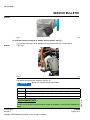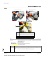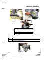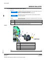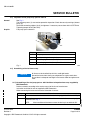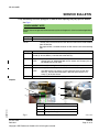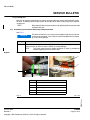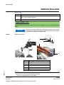
1
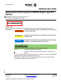
SB-912-063UL R1 SERVICE BULLETIN Replacement of fuel pumps for ROTAX® Engine Type 912 (Series) This SB revises the initial issue dated 24 June 2013. ATA System: 73-00-00 Fuel system RECOMMENDED Symbols used: Please, pay attention to the following symbols throughout this document emphasizing particular information. General note WARNUNG WARNING Identifies an instruction which, if not followed, may cause serious injury or even fatal injury. WARNUNG CAUTION Identifies an instruction which, if not followed, may cause minor or moderate injury. WARNUNG NOTICE Denotes an instruction which if not followed, may severely damage the engine or could lead to suspension of warranty. ENVIRONMENT NOTE Environment note gives you tips and behaviors to environmental protection. NOTE: Information useful for better handling. A revision bar outside of the page margin indicates a change to text or graphic. To obtain satisfactory results, procedures specified in this publication must be accomplished with accepted methods and prevailing government regulations. d05681.fm BRP-Powertrain GmbH & Co KG. cannot be responsible for the quality of work performed in accomplishing the requirements of this publication. 24 June 2013 Revision 1 Current valid documentation see: www.FLYROTAX.com Copyright - BRP-Powertrain GmbH & CO KG. All rights reserved. 73-00-00 Page 1 of 2 SB-912-063UL R1 SERVICE BULLETIN 1) Planning information 1.1) Applicability WARNUNG CAUTION NOTE: In accordance with the current Maintenance Manual LINE all mechanical fuel pumps have a 5 year life. Fuel pumps prior to 2008 (with S/N starting 07. or 06.) should have already been replaced in line with the routine maintenance requirements. If this 5 year replacement has been omitted the pump should be replaced with immediate effect. It is necessary to check the part no. & S/N of any pumps previously replaced to ensure that are not in the affected range. Basically, all fuel pumps with part no. 892542 and part no. 892546 are affected. Pumps with following serial numbers (S/N) are originally installed in the engines and/or delivered as spare parts and are affected by this replacement. All versions of the engine type: Engine type Serial number 912 UL from S/N 4,408.362 up to S/N 4,410.000 inclusive/6,770.101 up to 6,770.278 inclusive 912 ULS/ ULSFR from S/N 5,648.164 up to S/N 5,653.000 inclusive/6,374.055 up to S/N 6,374.205 inclusive/6,775.001 up to 6,775.038 inclusive/6,775.047 up to 6,775.174 inclusive/6,775.268 up to 6,775.390 inclusive/6,775.416 up to 6,775.733 inclusive/6,775.769 up to 6,775.994 inclusive/6,776.094 up to 6,776.099 inclusive/6,776.141 up to 6,778.295 inclusive In Addition all fuel pumps part no. 892542 from S/N 06.005924 up to 06.005981 inclusive/07.000529 up to 07.008428 inclusive/08.000001 up to 08.002984 inclusive/09.000001 up to 09.002805/10.000061 up to 10.005298 inclusive/ 11.000121 up to 11.000840 inclusive and fuel pumps part no. 892546 from S/N 06.005914 up to 06.005933 inclusive/07.000259 up to 07.008848 inclusive/08.000511 up to 08.002863 inclusive/09.000211 up to 09.002895 inclusive/10.000001 up to 10.005088 inclusive/11.000001 up to 11.000330 inclusive are affected, which has been installed at engine repair/ general overhaul. NOTE: The fuel pumps part no. 893110, 893114 and 893115 are not affected by this replacement. For complete instruction and compliance to this Service Bulletin refer to Service Bulletin SB-912-063, latest edition section 1.2 onward. Section 1.6) Approval: Is not required for engines of the type UL (Series). Section 3) Accomplishment: In addition: persons with adequate typespecific training. d05681.fm NOTE: 24 June 2013 Revision 1 Copyright - BRP-Powertrain GmbH & CO KG. All rights reserved. 73-00-00 Page 2 of 2 SB-912-063R1 SERVICE BULLETIN Replacement of fuel pumps for ROTAX® Engine Type 912 (Series) This SB revises the initial issue dated 24 June 2013. ATA System: 73-00-00 Fuel system RECOMMENDED Symbols used: Please, pay attention to the following symbols throughout this document emphasizing particular information. General note WARNUNG WARNING Identifies an instruction which, if not followed, may cause serious injury or even fatal injury. WARNUNG CAUTION Identifies an instruction which, if not followed, may cause minor or moderate injury. WARNUNG NOTICE Denotes an instruction which if not followed, may severely damage the engine or could lead to suspension of warranty. ENVIRONMENT NOTE Environment note gives you tips and behaviors to environmental protection. NOTE: Information useful for better handling. d05679.fm A revision bar outside of the page margin indicates a change to text or graphic. 24 June 2013 Revision 1 Current valid documentation see: www.FLYROTAX.com Copyright - BRP-Powertrain GmbH & CO KG. All rights reserved. 73-00-00 Page 1 of 14 SB-912-063R1 SERVICE BULLETIN 1) Planning information 1.1) Applicability WARNUNG CAUTION In accordance with the current Maintenance Manual LINE all mechanical fuel pumps have a 5 year life. Fuel pumps prior to 2008 (with S/N starting 07. or 06.) should have already been replaced in line with the routine maintenance requirements. If this 5 year replacement has been omitted the pump should be replaced with immediate effect. It is necessary to check the part no. & S/N of any pumps previously replaced to ensure that are not in the affected range. NOTE: Basically, all fuel pumps with part no. 892542 and part no. 892546 are affected. Pumps with following serial numbers (S/N) are originally installed in the engines and/or delivered as spare parts and are affected by this replacement. The part no. and S/N can be found on the edge of the mounting flange. All versions of the engine type: Engine type Serial number 912 A S/N 4,410.728 up to S/N 4,410.905 inclusive 912 F S/N 4,412.926 up to S/N 4,412.989 inclusive 912 S S/N 4,923.462 up to S/N 4,924.184 inclusive In Addition all fuel pumps part no. 892542 from S/N 06.005924 up to 06.005981 inclusive/ 07.000529 up to 07.008428 inclusive/08.000001 up to 08.002984 inclusive/09.000001 up to 09.002805/10.000061 up to 10.005298 inclusive/11.000121 up to 11.000840 inclusive and fuel pumps part no. 892546 from S/N 06.005914 up to 06.005933 inclusive/07.000259 up to 07.008848 inclusive/08.000511 up to 08.002863 inclusive/09.000211 up to 09.002895 inclusive/ 10.000001 up to 10.005088 inclusive/11.000001 up to 11.000330 inclusive are affected, which has been installed at engine repair/ general overhaul. NOTE: The fuel pumps part no. 893110, 893114 and 893115 are not affected by this replacement. 1.2) Concurrent ASB/SB/SI and SL Latest SI-912-020, regarding the general notes, measurements, changes etc. 1.3) Reason Field observation over the years has shown that in isolated cases failures of the mechanical fuel pump (part no. 892542 and 892546) can occur, which may subsequently lead to malfunctions. To prevent possible problems with the fuel system, the fuel pumps have to be replaced. 1.4) Subject - At the next scheduled maintenance event. - A replacement of the fuel pumps according to the instructions in section 3 has to be carried out May 01 2014 at the latest. WARNUNG WARNING Non-compliance with these instructions could result in engine damages, personal injuries or even fatal injury. 24 June 2013 Revision 1 Copyright - BRP-Powertrain GmbH & CO KG. All rights reserved. 73-00-00 Page 2 of 14 d05679.fm Replacement of fuel pumps for ROTAX® engine type 912 (Series). 1.5) Compliance SB-912-063R1 SERVICE BULLETIN 1.6) Approval The technical content of this document is approved under the authority of DOA ref. EASA.21J.048. 1.7) Labor time Estimated labor time: engine installed in the aircraft - - - labor time will depend on installation and therefore no estimate is available from the engine manufacturer. 1.8) Mass data change of weight - - none. moment of inertia- - - unaffected. 1.9) Electrical load data no change 1.10) Software accomplishment summary no change 1.11) References In addition to this technical information refer to current issue of - Illustrated Parts Catalog (IPC) - Heavy Maintenance Manual (HMM) NOTE: The status of Manuals can be determined by checking the table of amendments of the Manual. The 1st column of this table is the revision status. Compare this number to that listed on the ROTAX® WebSite: www.FLYROTAX.com. Updates and current revisions can be downloaded for free. 1.12) Other puplications affected none 1.13) Interchangeability of parts - Fuel pumps which are removed along with insulating flange (gasket), lock washers and nuts in accordance with chap. 3.1 are unserviceable and must be returned to your local ROTAX® Authorized Distributors or their Service Center. 2) Material Information 2.1) Material- cost and availability Price and availability and any possible support consideration will be supplied on request by ROTAX® Authorized Distributors or their Service Center. 2.2) Company support information d05679.fm Price and availability and any possible support consideration will be supplied on request by ROTAX® Authorized Distributors or their Service Center. 24 June 2013 Revision 1 Copyright - BRP-Powertrain GmbH & CO KG. All rights reserved. 73-00-00 Page 3 of 14 SB-912-063R1 SERVICE BULLETIN 2.3) Material requirement per engine parts requirement: New part no. Qty/ engine 945752 2 Lock washer A8 881360 1 Fuel pump set Old part no. Description Application fuel pump assy. - for fuel pump exchange consists of: 893110 1 Fuel pump assy. (consists of: 1x fuel pump part no. 893115 2x gasket ring part no. 250425 1x nipple part no. 840740 1x nipple part no. 840745 1x isolating flange part no. 950228 1x O-ring part no. 631870) - 942674 2 Hex. nut M8 - fuel pump assy. 851453 1 1-ear clamp 12.8-15.3 mm/0.50-0.60 in. - fuel pump assy. (inlet) 851463 1 1-ear clamp 10.8-13.3 mm/0.43-0.52 in. - fuel pump assy. (outlet) 851663 1 1-ear clamp 22.4-25.6 mm/0.88-1.01 in. - fuel pump assy. (inlet) 853313 1 1-ear clamp 17.8-21.0 mm/0.70-0.83 in. - fuel pump assy. (outlet) 2.4) Material requirement per spare part none 2.5) Rework of parts none 2.6) Special tooling/lubricant-/adhesives-/sealing compound Price and availability will be supplied on request by ROTAX® Authorized Distributors or their Service Center. Description Part no. Clamp/Mounting pliers n.a. 1-ear clamp When using the special tools, please note the information supplied by the tool manufacturer. d05679.fm WARNUNG NOTICE Application 24 June 2013 Revision 1 Copyright - BRP-Powertrain GmbH & CO KG. All rights reserved. 73-00-00 Page 4 of 14 SB-912-063R1 SERVICE BULLETIN 3) Accomplishment / Instructions NOTE: Accomplishment Before maintenance, review the entire documentation to make sure you have a complete understanding of the procedure and requirements. All the measure must be taken and confirmed by at least one of the following person or facilities: ROTAX® - Airworthiness representative ROTAX® - Distributors or their Service Center Persons approved by the respective Aviation Authority NOTE: All work has to be performed in accordance with the relevant Installation Manual and Maintenance Manual. Safety notice WARNING WARNUNG Proceed with this work only in a non-smoking area and not close to sparks or open flames. Switch off ignition and secure engine against unintentional operation. Secure aircraft against unauthorized operation. Disconnect negative terminal of aircraft battery. WARNUNG WARNING Risk of scalds and burns! Allow engine to cool sufficiently and use appropriate safety gear while performing work. WARNUNG NOTICE Should removal of a locking device (e.g. lock tabs, self-locking fasteners, etc.) be required when undergoing disassembly/assembly, always replace with new ones. 3.1) Removal WARNUNG NOTICE Ensure the fuel supply is turned off before disconneting any hoses. 3.1.1) Removal of fuel pump part no. 892542 (without crimped hose assembly), see Fig. 1 The following work steps are necessary: Step 1 Procedure Remove fuel hoses as per aircraft manufacturers instructions. NOTE: Loosen hex. nuts (13 mm/0.51 in) and remove fuel pump with lock washer A8 and insulating flange (gasket). d05679.fm 2 Make note of orientation of the hoses (inlet/outlet). 24 June 2013 Revision 1 Copyright - BRP-Powertrain GmbH & CO KG. All rights reserved. 73-00-00 Page 5 of 14 SB-912-063R1 SERVICE BULLETIN Graphic Fig. 1 09865 3.1.2) Removal of fuel pump part no. 892546 (with fire sleeve), see Fig. 2 Graphic Figure shows fuel pump part no. 892546 with crimped fuel hose assy. and fire sleeve. Fuel pump Fig. 2 09841 The following work steps are necessary (see Fig. 3): WARNUNG NOTICE Do not use any pliers with sharp surfaces. Procedure 1 Cut off the 1-ear clamp (1) of fire sleeve (2) with cutting pliers (3). 2 Slide back the fire sleeve (2) to make fuel hose accessible for cutting. 3 Pinch off the fuel hose with hose clamp pliers (4). ENVIRONMENT NOTE Ensure, that no fuel gets into the waste water system or the ground - risk of contaminating drinking water! 24 June 2013 Revision 1 Copyright - BRP-Powertrain GmbH & CO KG. All rights reserved. 73-00-00 Page 6 of 14 d05679.fm Step SB-912-063R1 SERVICE BULLETIN Graphic Slide back fire sleeve: Cut the band clamp: 1 2 3 Pinch rubber hose to prevent fuel leakage: 4 Part Function 1 Band clamp 2 Fire sleeve 3 Cutting pliers 4 Hose pinch pliers Fig. 3 09842,09843,09854 NOTE: Cut off the fuel hose with a very sharp knife, so that no cutting residues are produced. See Fig. 4. WARNUNG CAUTION Risk of cut injuries! Knives are sharp and may cause injury. Wear protective gloves. Step d05679.fm 4 Procedure The cut should be made adjacent to the crimped ferrel, to avoid losing any needed length. The fuel hose is reduced by approx. 20 mm (0.79 in.). NOTE: 5 Make note of orientation of the hoses (inlet/outlet) A clean cut surface is very important! Repeat procedure at the second fuel hose assy. 24 June 2013 Revision 1 Copyright - BRP-Powertrain GmbH & CO KG. All rights reserved. 73-00-00 Page 7 of 14 SB-912-063R1 SERVICE BULLETIN Graphic 3 1 2 4 Part Function 1 Fuel hose 2 Cutting knife 3 Crimped ferrule 4 Surface Fig. 4 09844,09845,09855 Step 6 Procedure Loosen hex. nuts (13 mm/0.51 in) and remove fuel pump with lock washer A8 and insulating flange (gasket). See Fig. 5. Fig. 5 24 June 2013 Revision 1 Copyright - BRP-Powertrain GmbH & CO KG. All rights reserved. 09846 73-00-00 Page 8 of 14 d05679.fm Graphic SB-912-063R1 SERVICE BULLETIN 3.2) Assembling of fuel pump assy. part no. 893110 See Fig. 6. WARNUNG NOTICE In addition to the insulating flange (gasket) also replace the O-ring at reassembly or assembly of the fuel pump. Both parts are included in the set of fuel pump assy. WARNUNG NOTICE Ensure the O-ring is located in the recess in the fuel pump, before installing the fuel pump! NOTE: Also all work has to be carried out in accordance with the aircraft manufacturer‘s instructions Step Procedure 1 Install fuel pump (5) with new insulating flange (gasket) (1) and O-ring (2). 2 Secure new hex. nuts M8 (4) and lock washer A8 (3) with LOCTITE 243 and tighten them evenly. Tightening torque 15 Nm (133 in.lb). Graphic Part Function 1 insulating flange (gasket) 2 O-ring 3 Lock washer A8 4 Hex. nut M8 5 Fuel pump assy. d05679.fm Fig. 6 24 June 2013 Revision 1 Copyright - BRP-Powertrain GmbH & CO KG. All rights reserved. 09847 73-00-00 Page 9 of 14 SB-912-063R1 SERVICE BULLETIN 3.3) Inspection of fuel pump assy. part no. 893110 General See Fig. 7. The fuel pump cover (1) must not be opened for inspection. Check the security markings (witness paint) (2). Check the connecting nipples (3)+(4) for tightness. If necessary secure them with LOCTITE 243. Tightening torque 10 Nm (88.5 in.lb). Fuel pump part no. 893110 Graphic 4 2 3 1 Steps Function 1 Fuel pump cover 2 Security marking (witness paint) 3 Connecting nipple - outlet (inner) D = 3.8 mm/0.15 in. 4 Connecting nipple - inlet (inner) D = 5.7 mm/0.22 in. Fig. 7 09848 3.4) Assembling of the fuel hoses assy. WARNUNG NOTICE All lines must be installed free of kinks, avoid tight bends. Prevent the hoses from chafing on components or against each other. Ensure there is adequate free length in the hose to allow for engine movement. 3.4.1) Assembling of the fuel pump part no. 893110 without crimped on hose assy. supplied by BRP-Powertrain Perform assembly according to the service manual of the aircraft manufacturer. Instruction and materials are not supplied by BRP-Powertrain. When connecting the hoses make sure the orientation is correct. Procedure 1 Connect the hose from the fuel tank to the connecting nipple identified as 4 in Fig. 7. 2 The hose that goes to the carburetors should be connected to the connecting nipple identified as 3 in Fig. 7. NOTE: After installation of the hoses ensure the fuel tap is turned back ON. 24 June 2013 Revision 1 Copyright - BRP-Powertrain GmbH & CO KG. All rights reserved. 73-00-00 Page 10 of 14 d05679.fm Step SB-912-063R1 SERVICE BULLETIN 3.4.2) Assembling of the fuel pump part no. 893110 when replacing fuel pump part no. 892546 See Fig. 8. ENVIRONMENT NOTE Ensure, that no fuel gets into the waste water system or the ground - risk of contaminating drinking water! Step 1 Procedure Remove hose clamp pliers from fuel hose assy. NOTE: Thereby, the fuel contained in the lines flow out and flush the residual debris from the fuel line. Be prepared with a suitable container and/or cloth to catch the outcoming fuel. Step Procedure 2 Before the fuel hose (2) is fitted with a 1-ear clamp (1), the two fuel hoses have to be marked (3) 16 mm (0.63 in.) from the end of the hose (2). 3 Slide all 4 1-ear clamps (1) on the fuel and fire sleeves. NOTE: Clamps part no. 853313/851663 on fire sleeve and clamps part no. 851463/851453 on fuel hose. 4 Slide the fuel hoses (2) onto nipple completely up to the end stop. 5 Crimp 1-ear clamp (1)- outlet side part no. 851463 with suitable crimp pliers . NOTE: 6 The edge of the 1-ear clamp (1) must align with mark (3) from fuel hose (2) , because otherwise there is too little space for the 1-ear clamp (1) of the fire sleeve. Repeat steps on inlet-side with 1-ear clamp (1) part no. 851453 for fuel hose assy. (2). Graphic 2 3 16mm 0.63 in. 2 2 1 d05679.fm Part Function 1 1-ear clamp 2 Fuel hose assy. 3 Mark (paint or tape) Fig. 8 24 June 2013 Revision 1 Copyright - BRP-Powertrain GmbH & CO KG. All rights reserved. 09849, 09850 73-00-00 Page 11 of 14 SB-912-063R1 SERVICE BULLETIN 3.4.3) Leakage test Because all fuel hose connections are visible and accessible now, inspect the whole fuel system for leaks. Therefore pressurize the system (for example by an electric fuel pump) with the operating pressure. NOTE: Reconnect of battery may be necessary for operating the fuel pump in order to perform this test. 3.5) Assembling of fire sleeves with crimp clamp connection See Fig. 9. WARNUNG NOTICE The distance from the 1-ear clamp (2) to the nipple flange (3) has to be measured, so that the outer 1-ear clamp (5) can be mounted on the fire sleeve (4) in the correct position. Step 1 Procedure Measure the distance at fuel hose assy. (1) from 1-ear clamp (2) to nipple flange sealing surface (3) and mark the fire sleeve (4) correspondingly. NOTE: Graphic The clamp securing the fire sleeve should be as close as possible but without impeding on the fuel hose clamp Distance measuring 5 4 1 2 3 Part Function 1 Fuel hose assy. 2 1-ear clamp 3 Nipple flange 4 Fire sleeve 5 1-ear clamp on fire sleeve 09851,09856 d05679.fm Fig. 9 24 June 2013 Revision 1 Copyright - BRP-Powertrain GmbH & CO KG. All rights reserved. 73-00-00 Page 12 of 14 SB-912-063R1 SERVICE BULLETIN See Fig. 10. Step Procedure 2 Push fire sleeve (fuel inlet) to stop and mount 1-ear clamp (17.8-21.0 mm/0.700.83 in.) with suitable crimp pliers. 3 Repeat steps for fire sleeve (fuel outlet) (22.4-25.6 mm/0.88-1.01 in.). ENVIRONMENT NOTE Ensure, that no fuel gets into the waste water system or the ground - risk of contaminating drinking water! WARNUNG NOTICE Graphic A drain line must be installed, that in the event of a internal leak any fluid is drained to a suitable location/position. See therefore Installation Manual of the relevant engine type and SI-912-020. Modification finished. 3 1 3 2 1 5 4 Part Function 1 Fire sleeve 2 Fuel hose assy. 3 1-ear clamp 4 Fuel pump assy. 5 Drain line d05679.fm Fig. 10 - Restore the aircraft to standard operating condition. - Connect the negative terminal of the battery. 24 June 2013 Revision 1 Copyright - BRP-Powertrain GmbH & CO KG. All rights reserved. 09853 73-00-00 Page 13 of 14 SB-912-063R1 SERVICE BULLETIN 3.6) Test run Conduct test run including ignition check and leakage test. NOTE: Due to the replacement with the new fuel pump automatically note the changed operating limit. See latest Operators Manual of the 912 Series. Also contact your aircraft manufacturer for further instructions. 3.6.1) Check of fuel pressure NOTE: The fuel pump part. 893110 has different characteristics as the fuel pumps part no. 892542 and part no. 892546. Low fuel pressure indications are possible and allowed. But the pressure must stabilize to the operating limit within 5 seconds. If not, the cause should be determined and rectified. Due to the technical design and installation conditions (construction of the return line, etc.) pressure fluctuations, at the fuel pump part no. 893110 are possible. These pressure fluctuations within the specified operating limits are not considered to a problem. 3.6.2) Check of float chamber Check float chamber for any debris particles. If any debris particles should be found then their source must be located. If necessary remove, clean and install again the float chamber. 3.6.3) Check drain line NOTE: A slight leakage on the drain line can be attributed to a slight "sweating" and not considered to be a issue. For a period of 1 minute after the engine has been stopped, no liquid must drip down. In case of uncertainty determine the oil amount. The maximum leakage is 0.5 ml for a 20 min engine run.. 3.7) Summary These instructions (section 3) have to be conducted in accordance with compliance in section 1.5. The execution of the recommended Service Bulletin must be entered in the engine logbook. Approval of translation to best knowledge and judgement-in any case the original text in German language and the metric units (SI-system) are authoritative. NOTE: The illustrations in this document show the typical construction. They may not represent full detail or the exact shape of the parts which have the same or similar function. Exploded views are not technical drawings and are for reference only. For specific detail, refer to the current documents of the respective engine type. 3.8) Enquiries d05679.fm Enquiries regarding this Service Bulletin should be referred to the ROTAX® authorized distributor of your area. A list of all distributors is provided on www.FLYROTAX.com. 24 June 2013 Revision 1 Copyright - BRP-Powertrain GmbH & CO KG. All rights reserved. 73-00-00 Page 14 of 14