1
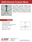
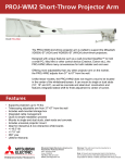
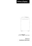
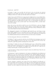
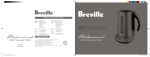
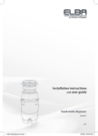
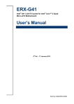
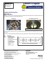
IMPORTANT: Please
read this bulletin and
pass on to others in
your organisation.
Dryer
Creaking Inlet Bearing Noise
MARKETS: USA only
MODELS: DEGX1, DGGX1
ACTION: If a creaking noise is encountered emitting from the inlet bearing area during operation, it could be due to either lack of
oil in the bearing or a defect in the housing bearing drum inlet.
Inlet Bearing
Housing Bearing Drum Inlet
Check for hairline cracks in the housing inner surface
There is no method to check for lack of oil in the bearing, however the bearing housing can be inspected for hairline cracks in the
inner surface.
Either way we would recommend fitting ‘Kit Bearing Inlet’, part number 479332. Included in the kit are the following components:
Part
479332
Description
KIT BEARING INLET
1 x Drum inlet cap screw
1 x Drum inlet cap
5 x Inlet bearing retainer screws
1 x Thrust washer
1 x Inlet bearing retainer
1 x Inlet drum bearing
1 x Bearing housing
1 x Shaft*
1 x Instruction sheet
Fisher & Paykel Appliances Ltd
78 Springs Road, East Tamaki, PO Box 58-732, Greenmount,
Auckland, New Zealand, Ph: 09 273 0600, Fax: 09 273 0656
Fisher & Paykel Customer Services Pty Ltd
A.C.N. 003 3335 171, 19 Enterprise Street, Cleveland, QLD 4163
PO Box 798, Cleveland, QLD 4163, Ph: 07 3826 9100, Fax: 07 3826 9164
Fisher & Paykel Appliances
150 Ubi Avenue 4, Sunlight Building #02-00, Singapore 408825
Ph: 6547 0100, Fax: 6547 0123
Fisher & Paykel Appliances Inc
27 Hubble, Irvine, California, CA92618, USA,
Ph: 949 790 8900, Fax: 949 790 8911
Fisher & Paykel Appliances Ltd UK
Ph: 08450 662200, Fax: 08450 662201
Exploded view of inlet bearing kit components
NZ = New Zealand
AU = Australia
ROW = International Markets
USA = United States of America & Canada
GB or UK = Great Britain & Ireland
EU = Europe
DR020.
October 2004
COPYRIGHT © FISHER & PAYKEL LTD 2004
ASSEMBLY METHOD
Step 1: Remove the drum inlet cap by unscrewing with a M5
or 3/16” allen key.
Step 2: Remove the 5 screws securing the bearing retainer
to the drum and remove the retainer.
Step 4: Refit in the reverse manner. Ensure that the bearing
housing is orientated so that the rivet heads sit in the
clearance holes, and the thrust washer is in place. Lift the
drum upwards while sliding the bearing onto the shaft. Do
not overtighten the screw securing the drum inlet cap.
Tighten to 10 Newton metres (7 foot pounds).
* Note:
It is important that all components contained
in this kit are fitted with the exception of the
shaft. This will only need to be replaced if there is any
evidence of damage on the surface of the shaft. For the
shaft replacement procedure refer to the SmartLoad
Service Manual, part number 517760.
Step 3: Lift the drum upwards slightly to take pressure off the
bearing, then rotate the bearing housing and slide the bearing
and the housing off the shaft.
Long Drying Times / Radio Frequency Interference
MARKETS: USA only
MODELS: DEGX1, DGGX1
ACTION: The screw that secures the power module to the base panel (see photo below) is used by the electronics to provide a
ground (earth) reference. If the screw is missing or not tightened sufficiently it can cause either long drying times (up to 3 hrs) or
radio frequency interference. It is recommended that this is the first thing to check for either of these problems.
This is not a safety issue as the ground is only used as a reference rather than an electrical grounding.
Power module screw
Note: When fitting or re-tightening the screw be careful not
to over-tighten it to the point where it can strip (the screw
only needs to be ‘nipped’ up).
DR020
October 2004
COPYRIGHT © FISHER & PAYKEL LTD 2004