1
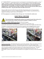
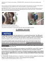
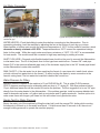
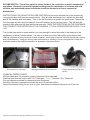
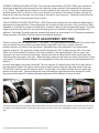
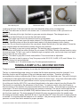
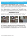
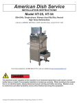
1
American Dish Service
INSTALLATION INSTRUCTIONS
Model 5AGES (ENERGY STAR) or WS2
Available in 90, 120, 150-second Time Cycles
Door-type, Double-Rack, Chemical Sanitizer, Dump & Fill Dishmachine
Listed by UL #E68594, NSF/ANSI 3, ASSE 1004 #933, LA Test Labs File M-780089, Mass. License P3-0111-306
If you have questions, call 800-922-2178 or visit our website at www.AmericanDish.com
The electrical power supplied to this machine is an imminent hazard that could result in severe
bodily injury or death if not properly installed or hooked up correctly. When working in the control
box or on electrical parts, always disconnect power and tag-out before servicing. Replace cover
to control box and other protective covers when finished servicing this equipment.
Copyright ADS Installation Manual Model 5AGES/WS2, Revision 3.0 6/7/2013
2
READ Manufacturer’s Manual before Using this Product. For your safety read and observe all
cautions shown throughout these instructions. While performing installations described in this
booklet, wear approved Personal Protective Equipment, including Safety Eye-Wear.
CHEMICALS— There are potentially hazardous situations when working with industrial cleaning
chemicals for dishmachines. See chemical manufacturer’s safe practices and MSDS sheets for
handling and installing chemicals and supply containers.
#1 BEFORE YOU BEGIN— American Dish Service provides this information as a service to our
customers. Keep all instructions for future reference. ADS reserves the right to alter or update
this information at any time. Should you desire to make sure that you have the most up-to-date
information, we would direct you to the appropriate document on our web site:
www.americandish.com. Set out below are the specifications and requirements that you must use
and follow to properly install the type or types of equipment listed above. It is your obligation as
the customer to ensure that the machine is installed safely and properly, and when completed,
the machine is left in proper and safe working order. Electrical, Plumbing, and Chemical hookup
should be performed by a qualified professional who will ensure that the equipment is installed
in accordance with all applicable Codes, Ordinances, and Safety requirements. Failure to follow
the installation instructions could void the warranty. ADS assumes no liability or control over the
installation of the equipment. Product failure due to improper installation is not covered under the
ADS Warranty.
#2 FLUSH OUT—Do not install spray arms until machine is flushed with water. When this machine
is turned on, it is normal for it to start and complete one cycle. First, fill and run a cycle. Do this
before installing the spray arms. Draining the water will flush installation debris from the tank and
pumps; this prevents damage to spray arm bearings. To drain, pull the two drain balls out of the
sumps.
#3 WATER HEATERS or boilers must provide the minimum temperature of 120°F required by the
machine listed above, which has a minimum hourly demand of 62.5 gallons per hour. The
recommended temperature range for optimal performance is 130-140°F. These specifications are
for the dishmachine only, which typically accounts for 70% of a restaurant’s hot water demand.
#4 IMPORTANT—The models of dishmachine listed in this document must be installed with space
around the outside to allow for servicing of motor and scrap accumulator as well as a 4” space
behind the machine from the wall.
#5 INSPECT FOR DAMAGE—If you receive a damaged dishmachine, do not sign “Clear” but write
“Damaged” on the documents.
#6 LOOSE ELECTRICAL CONNECTIONS—Damage to equipment can occur if the following
precautions are not observed. Before connecting power to the machine, check all electrical
terminals in the control box. Screws can loosen in transit. Loose connections on high amp load
terminals such as the pump motor will cause wire burning and component damage during
operation and will not be covered under ADS warranty.
Copyright ADS Installation Manual Model 5AGES/WS2, Revision 3.0 6/7/2013
3
#7 “CLEAN CIRCUIT” means the electrical circuit breaker for the dishmachine supplies no other
outlets, machines, or lights. GFCI outlets are not recommended for commercial dishmachines;
ADS recommends that a double-rack machine be installed with the wire connection (hard-wired)
directly from the circuit breaker. If a plug and socket are used to provide electrical power to a
dishmachine in a commercial kitchen, then according to electrical code it must be a GFCI, but not
all GFCIs are the same. They must be rated for the draw of the circuit.
Reference NEC Article 210.8 GFCI Protection (B) Other Than Dwelling Units (2) Commercial and
Institutional Kitchens. All 15 and 20A, 125V receptacles installed in kitchens, even those that do not
supply the countertop surface, must be GFCI protected.
#8 This equipment is considered an item of heavy use. It is not rated for outdoor use.
ELECTRICAL SECTION
The electrical power supplied to this machine is an imminent hazard that could result in
severe bodily injury or death if not properly installed or hooked up correctly
Electrical—5AGES, WS2 Double Rack (120 volt, 30 amps)
This equipment CANNOT BE CONNECTED TO OR OPERATED by 208-240v power.
A time cycle of 90-seconds is the shortest time available for this model and is compliant with NSF listing.
To change to a longer time cycle, the entire cam timer assembly must be changed because of motor
gearing. It is recommended that this equipment be installed using new circuit breaker or breakers.
Showing 5AGES control box w/tray in operating
position
Showing tray raised for service of pump motors
Top Mount Control Box: This dishmachine has two main/master switches. These are located on the back
of the control box and face to the rear. These switches open and close the power supply to their
respective motors: the right-hand switch controls the right-hand motor contactor and the right-hand pump
motor; the left-hand switch controls the left-hand motor contactor and the left-hand motor. The right
master switch (as you face the machine) controls power to the cam timer and control circuit. To
DISCONNECT power to the machine, both switches must be toggled to the left as you face the machine’s
front.
Copyright ADS Installation Manual Model 5AGES/WS2, Revision 3.0 6/7/2013
4
Showing single circuit wire combination
Showing the two master switches
If you choose Single Circuit Connection with One 30-Amp Power Supply: The power supply of 120 volt, 30
amps must consist of two 10-gauge copper wires and a suitable green ground wire. The breaker must be
on a clean circuit. ADS has provided a junction box for electrical hook-up with a threaded conduit hole for
1/2" conduit. The Junction box is attached to the back of the control box.
Remove the junction box cover and attach the 120 volt black supply wire to both black wires in the
junction box. Attach the white neutral supply wire to both white wires in the junction box. Attach a green
ground wire to the green ground screw located in the junction box and tighten all wires. After the machine
is powered up, TEST THE WHITE NEUTRAL WIRE to a ground source with a volt meter, it should read
0 to 6 volts. TEST THE BLACK WIRE to a ground source, it should read 110-120 volts. Attach a building
green ground wire to the green ground screw located in the junction box and tighten all wires. Replace
the junction box cover and control box lid. Label the 30 amp circuit breaker, “DISHMACHINE.”
Showing the dual circuit wire combination
Inside view of the junction box w/green ground
screw
If you choose Dual Circuit Connection with Two 15-Amp Power Supplies: For this optional connection, the
power supply to the dishmachine shall be two 120 volt, 15 amp circuits. The breakers or fuses must be
clean circuits. Each circuit must consist of two 12-gauge copper wires, one white and one black. Only
one single green ground wire is required for these power connections. ADS has provided a junction box
attached to the back of the control box for the electrical hook-up, with a threaded conduit hole for 1/2"
conduit. Bring both power circuits and a ground wire to this conduit box. The black and white wires with
solid color are for the first motor and control circuit, the black and white wires with red tracer lines are for
the second motor only. After connecting the wires and powering up the machine, test each circuit. TEST
THE WHITE NEUTRAL WIRE to a ground source with a volt meter, it should read 0 to 6 volts. TEST THE
BLACK WIRE to a ground source, it should read 110-120 volts. Replace the junction box cover and close
the control box lid.
Copyright ADS Installation Manual Model 5AGES/WS2, Revision 3.0 6/7/2013
5
Label the two 15 amp circuit breakers, “DISHMACHINE” noting there are twin circuits supplying the
machine.
The two motors for these models are rated 1HP at 9.5 amps at 115volts each for a total running draw of
19 amps allowing it to be installed on two 15-amp breakers or a single 30-amp breaker.
EXPLANATORY NOTE: The use of two solid color wires and two wires with red tracer stripes started in
2003, the solid color denotes the first motor (right-hand side) and control circuit wires. The red tracer
wires only go to the second motor (left-hand).
Showing connection points in 1 HP, 120v motor
black & white wires attach to spades left of two nuts
5AGES Door cut-off switch and lever arm
THIS MACHINE DOES NOT USE A BOOSTER OR TANK SUSTAINER HEATER.
PLUMBING SECTION
#1 TANKLESS water heaters can be problematic for commercial dishmachines. The ADS model
5AGES & WS2 dishmachine requires the full cycle amount of water (1.9 gallon) supplied within 7
seconds. It has been the experience of ADS that tankless supply systems require multiple units
plumbed in sequence with a recirculation loop to achieve proper pressure and temperature.
Check with the tankless water heater manufacturer, they may recommend a storage tank to
guarantee proper flow and line pressure to the machine. Failure to provide adequate water
quantity, pressure and temperature to the machine will cause the machine to function improperly
and is not the responsibility of ADS. Improperly installing ADS equipment in this manner could
void the warranty. All costs associated with providing an adequate water supply to the machine is
the sole responsibility of the user.
#2 HOODS—Follow all local plumbing and mechanical codes. IMC 2012, section 507.2.2 requires
Type II hoods for all commercial dishwashers except where the heat and moisture loads are
incorporated into the building’s HVAC systems or dishwashing equipment designed with separate
heat and moisture removal systems. A door-type, chemical sanitizing dishwasher is rated at 4770
Btu/h by table 5E, ASHRAE Research Project #1362, 8/5/2008. ADS DOES NOT SPECIFY BUILDING
HVAC VALUES
#3 DRAIN SIZE—Gravity drain lines are 2” pipe size. Do not use reducing adapters for drain lines,
always use same diameter pipe or larger. Close pump petcocks if equipped.
Copyright ADS Installation Manual Model 5AGES/WS2, Revision 3.0 6/7/2013
6
Hot Water Connection
Showing the ¾” pipe inlet, solenoid, and ASSE
certified air gap.
Typical name plate information and listing marks
WATER HEATER—Flush the building’s water lines before connecting to the dishmachine. Prior to
connecting plumbing, level the machine by adjusting the foot at the bottom of each leg up or down.
Water heaters or boilers must provide the minimum temperature of 120°F for this model of machine, which
demands an hourly minimum of 62 GPH. Temperatures above 150°F exceed the operational design
limits for this model. While the supply water must have a minimum of 120°F, 130-140°F is recommended
for best results. This model cannot be converted to high temp sanitizing by adding a booster.
INLET FLEX HOSE—Domestic style flexible braded hose should not be used to connect the dishmachine
to inlet water lines. The ID of the plastic liner for this type hose restricts flow. Connect 3/4" male pipe
thread (3/4” is the minimum allowable pipe size) of the hot water supply line to the 3/4" female pipe thread
on the dishmachine’s water inlet manifold.
SINK FAUCET—If the hot water line is also supplying the faucet of a pre-rinse sink, install check valves
on both cold and hot water inlets to the faucet— to avoid cooling the water by cross-connection in the
faucet’s mixing head. The hot water inlet manifold is behind the control box.
Water Pressure for Filling
Minimum pressure needed at the machine is 10 psi DURING the fill. This is called FLOW pressure.
STATIC pressure readings can be misleading and can drop to “0” during fill. With flow pressures below
10 psi, additional measures will be needed to resolve the problem. The first suggestion is to run 3/4" pipe
directly from the water heater to the dishmachine. If the problem persists, install a pressure bladder tank
used for domestic well water; a 5-gallon tank as a minimum and 10-gallon maximum. Another option is to
order a cam timer with longer cycle times but this will reduce hourly production rates.
Simple Test For Water Pressure
Empty the water out of the machine by lifting the drain ball, push the manual FILL button while counting
the seconds to fill back up to the water level decal. If it takes more than 20 seconds to fill, there is not
enough building pressure to operate the machine properly.
Copyright ADS Installation Manual Model 5AGES/WS2, Revision 3.0 6/7/2013
7
Drain Requirements
Showing the scrap box rear exit drain hub
connection
Showing scrap box as installed on 5AGES or
WS2
The 5AGES scrap box is shipped with the box installed in the normal operating position. To the rear of the
box there will be either a rear exit or bottom exit fitting (depending on how it was ordered) that fits a
rubber “no-hub” connector shipped inside the machine with the spray arms and paperwork. This
connector will fit 2” copper pipe or PVC tube. To prevent clogging, run drain lines as straight as possible.
Do not run drain plumbing with tight radius elbows or 180° bends. The use of floor sinks for drains can
cause flooding. Always run gravity drain lines downhill. Do not reduce the diameter of the drain pipe with
adapters, always use 2” pipe or larger.
Showing bottom exit for 5AGES & WS2
5AGES & WS2 rear exit scrap box
CHEMICAL FEEDERS SECTION
You must wear approved safety eye-wear before connecting chemicals. Read the chemical
manufacturer’s MSDS sheets. Chemicals can damage or corrode plumbing and stainless parts of
the dishmachine. Do not run chemical lines over controls or plumbing. Always secure chemical
lines and check regularly for leaks. If not properly handled, chemicals can cause serious bodily
injury. In the event of chemical contact to skin or eyes; wash immediately with fresh water and
seek medical attention.
Copyright ADS Installation Manual Model 5AGES/WS2, Revision 3.0 6/7/2013
8
DE-LIME SWITCH—The de-lime switch is placed inside of the control box to avoid unauthorized
operations. Because of potential hazards resulting from the combination of chlorine with acid
solution, only authorized trained individuals should be allowed to de-lime a commercial
dishmachine.
INSTRUCTIONS FOR USING THE DE-LIME FEATURE are first empty all water out of the machine by
removing the drain ball from the seated position. After all water has emptied out, replace the drain ball
and fill the machine with fresh water. Turn on the de-lime switch to operate the pump motor. Repeat this
first step again by removing the drain ball, then refill and turn on the de-lime switch. This will flush the
machine, refill again and this time add the de-lime acid. READ THE DIRECTIONS ON THE CONTAINER
FOR CORRECT CONCENTRATION OF THE CHEMICAL. TYPICAL CONCENTRATION LEVELS 1:20 to
1:60.
Turn the de-lime switch on again and let it run long enough to return the inside of the machine to the
appearance of shinny metal surfaces. It is best to de-lime more often with milder acid solutions than
waiting until there is heavy build up of white minerals, then trying to remove the build up with very strong
acid concentrations. Using too strong of an acid solution or running it for very long periods of time will
erode the metal of the impeller because it is spinning in the acid solution.
De-lime switch in control box
Warning decal about mixing chemicals
Impeller damaged from high acid
solution
CHEMICAL FEEDER PUMPS
ADS provides three (3) peristaltic pumps to dispense liquid chemicals
Chemical feed lines are color coded “Red” Detergent , “Green” Sanitizer, “Blue” Rinse-aid
Pick-up tubes are provided for chemical product containers
Sanitizer (chlorine) concentrations should be set at 50 parts per million
Inspect the transfer tubing for any cuts or holes, keep them protected and secured out of the way
Copyright ADS Installation Manual Model 5AGES/WS2, Revision 3.0 6/7/2013
9
Showing the control box with chemical pumps,
prime switches, red start and black fill switch
5AGES sump, drain ball, water level
decal, chemical tubes, scrap box
5AGES sump, drain balls and stainless filters
Optional Chemical Alarm switch, buzzer
Chemical alarm barb adjusting screw *
TYPE OF CHEMICALS—Use only commercial grade low-energy chemicals. For proper operation, use
non-foaming detergents and buffered sanitizer. Do not wash gold, pewter, silver, or silver-plate with
chlorine based sanitizers. High concentrations of chlorine sanitizers and caustic detergents will cause
damage to metals and welds. Do not exceed 50 parts-per-million (PPM) “free” or available chlorine, using
higher than 50 ppm will be dependent on local health requirements, however, the increased chlorine will
result in higher corrosion of metal parts. The resulting damage from overusing chlorine is not
covered under the ADS warranty. Purpose-built ware-washing dispensers are needed to properly meter
chemicals for wash and rinse. These dispensers are included with this model. Manually adding industrial
chemicals to the dishmachine is unsafe and not approved.
CHEMICAL LINES—Place color coded tubes into proper chemical containers. The containers need to be
as close to the machine as possible and sitting at floor level. This may require shortening of the flexible
chemical transfer tube. On the control box, there are chemical prime switches. There is a decal
identifying each switch. To prime chemicals use these momentary prime switches, verifying that all three
pumps rotate. If a chemical pump squeeze tube has taken a set (not allowing the pump to turn), manually
free the pump by pulling on the discharge side (right-hand) of the squeeze tube while pushing the prime
switch. Squeeze tubes should be replaced every six months.
CHEMICAL ADJUSTMENT—Chemical dispensing is controlled by a mechanical cam timer. All chemical
products must be adjusted for the product’s concentration and local water conditions. It will be necessary
to adjust initial factory setting (See page 10 for Cam Timer Adjustment Section). Water softeners should be
added to correct hard water conditions. Often hard water conditions are treated with the more expensive
ware washing chemicals, but it is more effective and less destructive to metals to soften the water before it
comes to the dishmachine.
Copyright ADS Installation Manual Model 5AGES/WS2, Revision 3.0 6/7/2013
10
AUDIBLE CHEMICAL ALARM OPTION—The optional chemical alarm (P/N 031-0326) uses a pressure
switch with a barb fitting that extends from the control box and connects to the chemical line by means
of a “t” fitting. The switch sends voltage to a buzzer located in the control box. Sensitivity is adjusted by
an Allen wrench (5/64” or 2mm) to turn a screw located in the center of the barb (see photo on page 9).
Remove the tube from the barb; turn the screw to the right for less sensitivity. Chemical buckets must be
placed on the floor for the pressure switch to work.
SOLID CHEMICAL PRODUCTS OPTION— ADS offers certain models with solid chemical dispensing for
detergents and rinse additives. These dispensers are mounted on the hood, next to the control box. Each
dispenser is controlled by a water solenoid that is mounted in place of the liquid peristaltic pump. The initial
signal comes from the cam timer. An optional metering relay is available for highly concentrated rinse
additives. Cold Water Products require a separate cold water line connected to a 1/4” female compression
fitting (provided). Hot Water Products require no additional plumbing.
CAM TIMER ADJUSTMENT SECTION
Timers for this model are available with 7-, or 8-cams. The cycle times are not adjustable. The cams of the
timer are wheels whose positions are either fixed or adjustable. Each cam controls a specific
machine function, as noted on the timer decal. Adjustable cams are comprised of two wheels held
together at the hub. The perimeter of each wheel is divided into 180° of high cam and 180° of low cam.
When one of these wheels is rotated on the hub in relation to the opposing wheel, the two lower cam
segments can form a notch in the perimeter. Above each cam is a timer switch with a metal finger that
rides along the outer edge of the cam. When the finger drops into the lower cam notch, the function of that
cam begins. To widen the notch (length = time energized) or close the notch use the timer adjustment tool,
which is
provided and taped to the control box shelf. This tool has two (2) raised buttons that fit into the holes on
the side of each wheel. The factory sets the start of each function using the right-side wheel of the cam.
TO ADJUST rotate only the left-side cam wheel. The left-side of the wheel controls the point when that
specific functions ends. Factory settings are only initial settings, adjustments will be required for each
chemical and the water fill time because water pressures will be different for every account.
The left photo shows arrow is pointed at the left-side wheel of the cam which is used to lengthen or shorten the low cam or the
time ON for the respective switch. Center photo shows high-cam & low-cam notch. Adjustable cams are colored either black or
gray.
Copyright ADS Installation Manual Model 5AGES/WS2, Revision 3.0 6/7/2013
11
Cam adjusting tool
Chlorine test strips
Spray arm pressure tester #088-1048
Looking at the front of the cams with the cam timer assembly sitting on its mounting base:
#1 Cam: The white cam on the left is the master cam. It controls the total time of the cycle and is not
adjustable.
#2 Cam: Continuing left to right, this black or gray cam controls detergent. The detergent cam is
adjustable and should begin as soon as the wash action starts.
#3 Cam: This white cam controls the drain time and is not adjustable.
#4 Cam: The H2O or fill cam opens the water solenoid. Too little water will cause the pump to cavitate
(surging). Overfilling does not allow the soiled wash water to fully drain between cycles, causing
carry-over. Do not move the right side of the cam wheel. Adjust the left-side of the cam wheel to close the
water solenoid when the dishmachine reaches full spray arm pressure.
#5 Cam: This black or gray cam controls sanitizer. The sanitizer cam is adjustable. Set sanitizer
concentrations at 50 parts per million (Notice: Do not exceed 100 PPM’s). Monitor chlorine levels by using
chlorine test strips. To Test—run a rack of dishes through a complete cycle, use the test strip to test water
samples from the top of any glass.
#6 Cam: This black or gray cam controls rinse additive. The rinse-aid cam is adjustable.
#7 Cam: This cam is used to pause or “burp” the pump on the 3D-S, ES, 5-AGS, 5-CD, and L Series. It is
set at the factory but can be adjusted.
#8 Cam: Available on 2 1/2 minute timers only. Provides prewash/wash/rinse.
TUNING A DUMP & FILL MACHINE SECTION
Tuning is essential for proper cleaning, do not skip this IMPORTANT PROCEDURE.
The key to understanding proper tuning is to realize that the drain sequence cannot be changed. It is a
fixed time function and the regulator of the cycle between wash and rinse. Therefore, all tuning is
accomplished by setting or adjusting the fill cam in relationship to the fixed drain cam. The goal of tuning is
to eliminate all soiled wash water through the drain, before the drain closes. A sign that soiled wash water
has exited the tank will be the typical hollow sound of a pump running without water.
It is at this point that the H2O (FILL) cam should be adjusted so the water solenoid turns the fill water ON.
That function is controlled by the adjustment of the fill cam. For optimum results, allow the fill water to
flush the interior of the machine for a few seconds before the drain closes. Once the drain is closed the fill
cycle begins. Fill must continue until full spray arm pressure is reached. This can be verified with the use
of a spray arm pressure tester (Kit #088-1048) attached where one of the end plugs are usually screwed
into the lower wash arm. The tester gauge will indicate full spray arm pressure when the needle stops
fluctuating and remains steady. Adjust the fill cam to turn the water OFF when this point of steady pressure
is reached. It is important that the machine is not overfilled. Use just enough water to reach full spray arm
pressure, no more than that is needed for proper operation.
Copyright ADS Installation Manual Model 5AGES/WS2, Revision 3.0 6/7/2013
12
90-second timer operation for 5AGES or WS2
[Pump shut off]-[*sanitizer here]
START [------WASH 50-Seconds----------------] - [--DRAIN 7-Sec--] - [--33-sec to FILL and RINSE---] END
[*detergent here]
[-Fill until FSP is reached-]
If a pressure gauge tester is not available, an approximation of full spray arm pressure could be
determined by the sound of the spray arms. There would be a typical continuous swishing sound of the
water spraying. Again, when this sound is heard, that would be the point to turn the water OFF. Seven
seconds of full spray arm rinse pressure is required by health code. In the event air is trapped in the pump
during fill, a vapor lock can occur where the pump is turning but there is no spraying.
If this vapor lock occurs, check incoming water temperature and reduce the temperature if it is above
140-150°F. Operating temperature of 120°F is the minimum, 130-140°F is recommended. If the problem
is caused by low water pressure to the machine, see the Plumbing Section on page 5 to correct that
condition. If vapor lock is still present, electrically stop or pause the pump to release air. This the machine
has a 7-cam timer, this pause feature is wired into the 7th cam from the factory.
DOOR AND ARM SECTION
Door arm alignment is corrected by bending the door arm so each door closes at the same place. The
pictures below show a corner machine because it is easier to see the door match up. But the same
alignment of the arm is true of a double rack as seen in the picture to the right.
Showing misaligned arms on corner
Showing correct arm alignment
Shown on a double rack machine
Care should be used in transporting and placing the machine, watch that the door arm is not twisted or
bent. When dish tables are attached, watch that they do not bind and bend the door guides by lifting
against the machine. This will cause binding of the guide on the door. When one door is standing above
the top of the hood while the other door is resting down on the hood, this is caused by a door arm that is
bent—hold one door arm handle down while lifting the handle of the other to align the arm handles. Use
enough lifting force to bend the arm back into the correct position.
Copyright ADS Installation Manual Model 5AGES/WS2, Revision 3.0 6/7/2013
13
FINAL INSTALLATION CHECK LIST
1 Check to be sure power is disconnected at the circuit breaker(s) and the control box is switched OFF.
2 The master switches are located on the back of the control box for all Top Mount machines, under the
control box on Front Mount machines. Open door and remove all packaging, save all instructions for
future reference.
3 Remove the white protective film from doors, front panel, and control box.
4 CHECK DISHTABLE placement, correct any binding or pinching caused to the dishmachine door
guides by dishtables during installation.
5 TURN ON water supply. Check for leaks. Tighten connections if needed.
6 TO OPERATE, turn on the main power circuit breaker(s) and switch the dishmachine master switches
to ON position. Remove spray arms and manually fill the machine with water using the fill switch (labeled
FILL). This switch is located on the front of the control box. Run one complete cycle by closing the doors
(optional auto/start machine only) or pushing the start switch (labeled START). This is the flush cycle,
which removes installation debris from wash tank and pump.
Spray arm bearing with sealing o-ring
Spray arm end caps
5AGES spray arm (six jets)
7 AFTER FLUSHING, install the spray arms. These arms are interchangeable upper and lower. Failure to
follow this flush procedure can damage spray arm bearings. Observe the water level decal. This decal is
located on the outside of the sump area next to the drain tube of the machine. This mark is the
approximate level for initial fill. Verify incoming water temperatures 120°F minimum, note that 130-140°F
is recommended.
8 INSPECT THE SUMP area and verify pump filters are in place. Verify that chemical feed lines are in
their proper container and that lines are primed. Post an operational wall chart close to the machine.
Do not open doors while machine is in cycle. Doing so could result in serious bodily injury from
spraying hot water and chemicals.
Copyright ADS Installation Manual Model 5AGES/WS2, Revision 3.0 6/7/2013
14
APPENDIX
089-9393---5AGES/WS2 Parts Manual
089-9401---Service Manual
089-9430---Brochure
089-9364---Wall Chart
089-9447---Wire Diagram
089-9414---Spec Sheet
089-9387---5AGES, WS2 Installation Manual
Copyright ADS Installation Manual Model 5AGES/WS2, Revision 3.0 6/7/2013
15
ADS WIRE CHART (LADDER)
MODEL: 5-AG, 5-AGS, 5AGES
MASTER SWITCH
NEU
NEU
L1
L1
CONNECT TO ELEC SUPPLY SOURCE
USING 12-10 AWG COPPER WIRE (2 CIRCUITS)
120 VOLT
CIRCUIT PROTECTION: 20 AMP BREAKERS
OR FUSE WITH A 20 AMP RATING
2ND OPTION
40 AMP SINGLE BREAKER, 8 GA WIRE
120V
DOOR
START
Motor
CAM TIMER
90-Second cycle
DET PRIME
DETER PERISTALTIC
BUZZER
PRESS SW
CHEMICAL ALARM
SAN PRIME
SANI PERISTALTIC
RIN PRIME
RINSE PERISTALTIC
DRAIN SOL
FILL
WATER SOL
PUMP MOTOR
PUMP MOTOR
Copyright ADS Installation Manual Model 5AGES/WS2, Revision 3.0, 6/7/2013