1
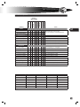
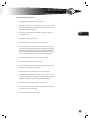
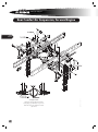
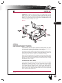
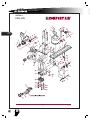
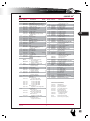
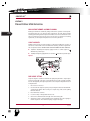
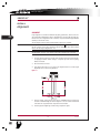
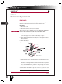
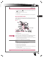
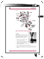
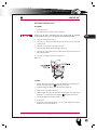
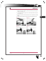
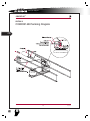
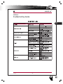
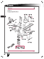
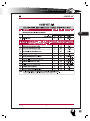
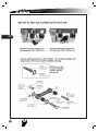
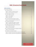
Rear Axle & Suspension
Overview
Rear Suspension
This chapter includes routine maintenance and a procedure for removal of the axle
and suspension from the bus chassis. Manufacturer’s documentation is provided in
the appendixes and on the TechReference CD for more involved servicing of the axle
and suspenion components.
All Americans are equipped with one of three rear suspension systems:
Hendrickson™ Softek.™ The Softek rear suspension is a 13-leaf (AAFE) or 14leaf(AARE) slipper spring configuration, and is standard equipment on both Front
Engine and Rear Engine All American.
Hendrickson™ Comfort Air.™ The Comfort Air rear suspension is a trailing arm configuration with 2 heavy duty rolling lobe air springs mounted rearward of axle and
steel springs forward of the axle. The system features a quick align dog tracking adjustment. A transverse track rod controls lateral motion. Vertical motion is controlled
by two 13/8” bore Sachs shock absorbers. A single height control valve maintains suspension height at varying loads.
Ridewell™ Model 227. The Ridewell 227 rear suspension is a 4-bag air spring suspension incorporating a parallelogram linkage, and is optional on Rear Engine All
American only. Vertical motion is controlled by adjustable heavy duty Koni shock
absorbers. Two leveling valves permit leveling side to side and front to rear. Axle dog
tracking is adjustable via eccentric torque arm bolts.
267
Single Reduction Rear Differential Carriers
Meritor Publication Maintenance Manual 5A
Forward Engine Rear Axle
Meritor single reduction speed with synthetic bearing lubrication. Standard model is
RS21-145; 21,000 lb GAWR; 5.29:1 reduction ratio. All American FE may be equipped
with optional models depending upon GVWR and reduction ratio, suspension, and/
or brakes options:
Meritor Model
RS19-144
RS21-145
RC23-160
RS23-160
GAWR
Details
19,000 lbs
21,000 lbs Standard.
23,000 lbs
23,000 lbs
Rear Engine Rear Axle
Meritor single reduction speed with synthetic lubed bearings. Standard model is
RS23-160; 23,000 lbs. capacity; 5.38 to 1 ratio. All American RE may be equipped with
optional models depending upon GVWR and reduction ratio, suspension, and/or
brakes options:
Meritor Model
RS19-144
RS21-145
RC23-160
RS23-160
GAWR
Details
19,000 lbs
21,000 lbs
23,000 lbs
23,000 lbs Standard.
The specific axle model installed may be identified by refering
to the axle data plate affixed to driveshaft side (front on
Forward Engine, rear on Rear Engine) of the axle’s housing.
RIDEWELL
SUSPENSION
2
APPENDIX
comfort air
rear suspension
1
APPENDIX
L
service manual
Whether the bus is equipped with air or hydraulic brakes, wheel hubs and brake
drums or rotors are mounted similarly. The wheel hub (with either an attached drum
or rotor) is mounted upon to the axle spindles. Axle shafts pass through the center
of the spindles and bolt to the outer flange of the wheel hub. Thus, the rear wheel
bearings are lubricated by the axle oil. Synthetic axle lubricant is standard.
268
[CAUTION] Towing the bus with the rear wheels on the road requires removal
of the rear axle shafts in order to avoid potential damageto the automatic
transmission. See Jacking & Towing in the Specs & Maintenance chapter for
the required procedure.
Appendixes In This Chapter
[For Hendrickson Softek suspension service procedures, see Front Axle & Suspension
chapter, Appendix 1.]
Appendix 1. Comfort Air Rear Suspension. Hendrickson Technical Procedure number 17730-246 covers maintenance, disassembly, adn troubleshooting for the Comfort Air rear suspension.
Appendix 2. Ridewell Air Rear Suspension. Ridewell publication covers maintenance, adjustment, and component replacement information on the Ridewell front
and rear air suspension
On The TechReference CD
Rear Axle. Arvin Meritor Maintenance Manual 5A includes thorough servicing information on the disassembly, inspection, and servicing of the rear axles, differential,
and reduction gears. The axles used on Blue Bird All Americans are single-speed axles
without Driver Controlled Main Differential Lock (DCDL).
Also See…
The Hydraulc Brakes chapter of this manual includes a detailed procedure for removing the rear disc rotor/hub assembly.
Maintenance
Maintenance of the rear axle and suspension consists of periodic general inspection,
checking tightness of fasteners, and axle lubrication fluid level check and/or replacement. Refer to the maintenance charts on the next page (also included in the Specs
& Maintenance chapter) for intervals and lubricant specs.
L
rear axle
&
suspension
Rear Axle & Suspension
Interval:
Months/1000 Miles
Rear Axle
Check lubricant
Change Lubricant, Petroleum Based
Change Lubricant Synthetic
Spring Suspension
Inspect visually
Check rebound pins
Torque spring radius fasteners
Torque shock mounting bolts
Torque U-bolt fasteners
Air Suspension
Inspect visually
Torque upper shock mount
Torque lower shock mount
Check ride height
Check U-bolts 7/8-14 UNF 28
Check U-bolts 3/4-16 UNF 28
Torque lower shock mount to spring
Torque air spring anchor bolts
Torque quick align bolts
Torque lever linkage locknut
Torque Leveling valve mount bolt
12 / 100,000
12 / 50,000
12 / 24,000
12 / 12,000
6 / 10,000
6 / 6,000
1 / 10,000
operation
first 1000 miles
whichever occurs first
•
•
•
•
notes
Hypoid Gear Oil. Capacity: 35 pints (16.9 litres).
For viscosity recomendation, see Axle Lubricant chart, below.
269
•
•
•
•
•
•
•
•
•
•
•
•
•
•
•
•
•
•
•
Verify that cotter pins are installed.
TIghten locknuts to 100–125 ft·lb (11–14 Nm).
Tighten locknuts to 75–100 ft·lb (9-11 Nm).
Torque U-bolts to 300–350 ft·lb (34–39 Nm).
Check for wear, damage; loose or missing parts.
Tighten to 50–70 ft·lb (68–95 Nm)
Tighten to 150–180 ft·lb (203–244 Nm)
Shock length, eye to eye: 22.68” ± .25”. (576 ± 6 mm)
Tighten to 400–450 ft·lb (542–610 Nm)
Tighten to 260–320 ft·lb (353–434 Nm)
Tighten to 260–320 ft·lb (353–434 Nm)
Tighten to 20–30 ft·lb (27–41 Nm)
Tighten to 525–575 ft·lb (712–800 Nm)
Tighten to 100–150 in. lbs. (11–17 Nm)
Tighten to 60–85 in. lbs. (7–10 Nm)
Rear Axle Viscosity /Temperature Chart
Meritor Lubricant Specification
Description
Cross Reference
Minimum Outside Temperature Maximum Outside Temperature
0-76-A
Hypoid Gear Oil
GL-5, S.A.E. 85W/140
+10° F (-12.2° C)
*
0-76-B
Hypoid Gear Oil
GL-5, S.A.E. 80W/140
-15° F (-26.1° C)
*
0-76-D
Hypoid Gear Oil
GL-5, S.A.E. 80W/90
-15° F (-26.1° C)
*
0-76-E
Hypoid Gear Oil
GL-5, S.A.E. 75W/90
-40° F (-40° C)
*
0-76-J
Hypoid Gear Oil
GL-5, S.A.E. 75W
-40° F (-40° C)
+35° F (+1.6° C)
0-76-L
Hypoid Gear Oil
GL-5, S.A.E. 75W/140
-40° F (-40° C)
*
* No upper limit on these temperatures. However, axle sump temperature must never exceed + 250° F (121° C ).
L
service manual
Rear Softek Suspension
(Forward Engine Shown)
1
29.40
270
2
20
3.84 Forward Engine
2
1
3.34 Rear Engine
20.60
C/L
75-100 ft. lbs.
REA
RA
XLE
10
15
13
(Forward Engine Shown)
12
75-100 ft. lbs.
9
9
(Forward Engine Shown)
11
16
15
26
100-125 ft. lbs.
25
8
7
5
24
25
4
0077616p
280-310 ft lbs.
L
rear axle
&
suspension
Rear Softek Suspension Installation
1. Install spring hanger brackets (items 10 & 11) as shown.
2. Install pad assembly (item 13) using fasteners shown. The pad assembly
should be installed so that the bracket makes contact with the bottom of the
frame rail before tightening fasteners.
3. Place springs in the rear suspension installation jig with the radius leaf toward front of chassis.
271
4. Select proper axle per production order.
5 install saddle (item 5) over axle dowels at 40.00 spring centers.
6. Place axle housing on axle saddles (item 5) w/ axle centered on springs. To
center axle housing,measure distance between outside edge of spring stack
and inboard face of brake mtg. Flange (see detail a) for both left & right sides.
Move axle side to side if required until difference of left & right measurement
is .38 or less. Axle saddle (item 5) is to remain centered on spring (item 7.)
7. Square axle saddle with axle housing ± .06 at outer edge of pad.
8. Install u-bolt bracket (item 4) and spherical washers.
9. Install u-bolts (item 9) with u-bolt seat (item 8), between u-bolts and top of
spring. Note u-bolt length variations by model.
10. Install shock on shock arm of bracket (item 4) as shown in diagram.
11. Use hardened flat washer and hi-nut on ends of u-bolts. Torque to 300-310
ft·lb. To prevent distortion of u-bolts, tighten nuts simutaneously w/4 spindle
equipment or alternately in diagonal pattern w/manual equipment.
12. Install frame mounted shock brakets (items 1 & 2) as shown.
13. Install inner dual tire and wheel assemblies temporarily for movement of
spring and axle assembly only. (if req’d)
14. Assemble spring and axle assembly to chassis.
L
service manual
15. When spring assembly makes contact with the rear spring hanger bracket
(item 10), install rebound pin (item 15). Install cotter pin thru rebound pin as
shown. (both sides of casting) when spring assembly makes contact w/ frt
spring hanger brkt (item 11), install rebound pin (item 15). Install cotter pin
thru cotter pin hole in casting and rebound pin as shown.
272
16. Attach spring radius leaf pin to front side of hanger (item 11), using fasteners
as shown. Torque 5/8 fastener to 100-125 ft·lb.
17. Install shocks (item 12) as shown. If axle housing interferes with installing
bolt, reverse bolt direction. Torque shock mounting 3/4 fasteners to 75-100
ft·lb.
18. If axle dog track adjustment is required, follow procedure below:
18.1 using beeline or other suitable equipment, make standard check for
drive axle dog tracking. If laser mark is within 1/4” of center, no further
alignment is required. Skip to step c).
18.2 if laser mark is greater than 1/4” from center, loosen fasteners (item
24) and add shims (item 16*) as req’d. Add only equal number of shims
on each side of spring. Tighten fasteners and re-check alignment. Repeat step until laser mark is within 1/4” of center.
18.3 torque fasteners 100-125 ft-lbs.
19. See appropriate fuel tank & barrier installation diagram for part numbers and
fasteners.
20. Due to initial relaxation and/or seating of suspension to axle connection
hardware, retorquing of nuts on suspension u-bolts (items 9) prior to delivery is required. A minimum of two tightenings, one at initial assembly & one
after body mount.It is preferable to do second one after road test, but anytime after body mount is acceptable.
L
rear axle
&
suspension
273
L
service manual
Rear Comfort Air Suspension, Forward Engine
L
274
L
K
M
K
L
K
K
L
K
K
Centering Axle on Frame
Measure from outside face of frame rail web to brake
mounting flange, edge of brake drum, or edge of new tire.
Measure both sides of chassis. Measurements should be
equal within 1/4”.
L
0040114ff
M
rear axle
&
suspension
Torque Requirements
key
A
B
C
D
E
F
G
H
J
K
L
M
description
torque
U-bolt (High Locknut), 7/8”-14 Unf 2b
425 Ft.lbs.
3/4”-16 Unf 2b
290 Ft.lbs.
Cross Channel To Main Support Mbr, 3/4”-10 Unc 2b
290 Ft.lbs.
Air Spring To Cross Channel, 1/2”-13 Unc 2b
25 Ft.lbs.
Quick Align Joint, Right Side Only, 1”- 8 Unc 2b
550 Ft.lbs.
Quick Align Joint, Left Side Only, 1”- 8 Unc 2b
550 Ft.lbs. (100 Ft-lbs During Alignment)
Shock Absorber, Upper Shock, 1/2”-13 Unc 2b
60 Ft.lbs.
Shock Absorber, Lower Shock, 3/4”-10 Unc 2b
170 Ft.lbs.
Linkage Rod Assy Locknut, 5/16”-24 Unf 2b
125 In.lbs.
Leveling Valve Mounting, 1/4”-20 Unc 2b
72 In.lbs.
Capscrew, 5/8”-11, Gr8
110 Ft.lbs.
Air Spring Stud Nut, 3/4”-16
25 Ft.lbs.
Hanger Assembly Nut, 3/4”-10
175 Ft.lbs.
275
L
service manual
Rear Comfort Air Suspension, Rear Engine
276
L
K
L
M
K
M
K
L
K
K
L
K
M
M
0040115J
Centering Axle on Frame
Measure from outside face of frame rail web to brake
mounting flange, edge of brake drum, or edge of new tire.
Measure both sides of chassis. Measurements should be
equal within 1/4”.
L
rear axle
&
suspension
Torque Requirements
key
A
B
C
D
E
F
G
H
J
K
L
M
description
torque
U-bolt (High Locknut)
400-450 ft·lb
Cross Channel To Main Support Mbr
260-320 ft·lb
Air Spring To Cross Channel
20-30 ft·lb
Quick Align Joint Right Side Only
525-575 ft·lb
Quick Align Joint Left Side Only525-575 ft·lb /(100 ft·lb during alignment)
Shock Absorber, Upper Shock
50-70 ft·lb
Shock Absorber, Lower Shock
160-180 ft·lb
Linkage Rod Assy Locknut
100-150 ft·lb
Leveling Valve Mounting
60-85 ft·lb
Capscrew, 5/8”-11, Gr8
90-122 Ft.lbs.
Air Spring Stud Nut, 3/4”-16
25 Ft.lbs.
Hanger Assembly Nut, 3/4”-10
155-210 Ft.lbs.
277
L
service manual
Rear Ridewell Suspension, Rear Engine
G
278
B
F
B
H
F
F
D
C
D
F
F
F
F
B
G
17.53 + .25
F
B
A
A
F
H
E
C
Bottom of frame rail
welds
8.00±.25
Top of mounting plate
Anti-turn Washers
0042329h
See Ride Height Adjustment
L
rear axle
&
suspension
Torque Requirements
key
A
B
C
D
E
F
G
H
description
Air Spring Stud Nut
Air Spring Stud Nut
U-Bolt Nuts
Sway Bar L’Nut
Hanger Beam L’Nut
Hex Nut, 1/2”-13, Grd 8
Hex Nut, 5/8”-11, Grd 8
Suspension Hanger, Hex Nut, 3/4”-10, Grd 8
torque
25 ft·lb
50 ft·lb
350 ft·lb
460 ft·lb
1000 ft·lb
56 ft·lb
160-180 ft·lb
155-210 ft·lb
279
L
service manual
Ride height
Ride height is defined as the distance between the axle and the bottom of the frame
rail, and may be verified by measuring either shock length or air spring height:
280
Ridewell Ride Height (Frame to Axle):
Shock length @ Ride Height
Hendrickson:
Ridewell:
Air Spring Ride Height:
8.50” ±0.25”
22.68”±0.25” (eye to eye)
17.53” ±0.25” (eye to eye)
8.0±0.25”
Ride Height Adjustment Air Suspension
1. Vehicle to be on level ground with 70-120 psi system air pressure maintained.
Left and right rear height control valves to be adjusted independently.
2. Remove vertical rod from first valve horizontal arm & from lower stud. Rotate
horizontal lever arm down to fully exhaust air springs.
3. Rotate horizontal lever up, filling air springs until affected side of vehicle is at
specified ride height. Bring arm to neutral (horizontal) position when proper
height is reached.
4. Place centering pins in valve to hold arm horizontal. Insert vertical link into
upper connector, sliding up or down until lower grommet can be pushed
onto lower mounting stud. Tighten hose clamp on upper connector and remove centering pins from valve.
5. Remove vertical link lower grommet from mounting stud and rotate horizontal link down to exhaust air.
6. Reinstall grommet on mounting stud and recheck ride height.
7. If adjustments are necessary, loosen hose clamp, slide connector up or down
as required. Tighten clamp and repeat steps 5 & 6 until ride height measurement is within specifications.
8. Repeat steps 2-7 for 2nd valve.
Drive Axle Alignment—Ridewell Air Suspension
1. Center axle in chassis, as follows:
L
1.1 With chassis at normal ride height,measure from outside face of frame
rail web to drive axle brake-mounting flange,edge of brake drum, or
edge of tire (w/new tires only). Do for both sides. If measurements are
within 1/8” skip to step 4.
rear axle
1.2 Loosen track rod pinch bolts and with pipe wrench, rotate track rod
shaft (item #18) to move frame laterally relative to axle.
1.3 Repeat steps 1) and 2) until axle has been centered within 1/8”.
1.4 Retighten pinch bolts to 150 ft-lbs.
&
suspension
2. Axle Dog-Track Alignment
2.1 Using beeline or other suitable equipment, make standard check for
drive axle dog tracking. If laser mark is within 1/4” of center, no further
drive axle alignment is required. Skip to step 3).
2.2 If laser mark is greater than 1/4” from center, loosen nuts (item #28),
Rotate eccentric bolts (item #27) on appropriate side to center laser
mark. Rotate both upper and lower eccentric bolts equally. Rotating
eccentric bolts on both sides of chassis (in opposite directions) may
be required to center laser mark.
2.3 Torque drive axle eccentric bolt nuts (item #28) to 1000 ft-lbs.
2.4 Add anti-turn washers (item #26) over head of eccentric bolt (item
#27) and weld to receiver ring.
281
Adjusting of Koni Shocks
1. Remove the shock absorber from the vehicle. Place the lower eye attachment In a vise. Fully collapse shock absorber while turning dust cap to the
left (counterclockwise) until it is felt that cams of internal adjusting nut engages in the recesses of the internal foot valve. While engaged, turning the
dust cap fully counterclockwise puts the shock at its minimum dampening
setting. Skip to step 3) if no damping increase is required.
2. Keeping shock absorber collapsed, turn dust cap to the right (clockwise) until
a stop is felt. Stop turning and do not use any more force!! This Is the maximum dampening setting. To reduce dampening, turn counterclockwise.
3. Pull shock absorber out vertically without turning for at least 3/8” to disengage the adjusting mechanism. The dust cap may now be turned freely.
Shock absorber can then be re-fitted to the vehicle. When reinstalling, tighten shock absorber upper & lower nut (item #23) until a dimensionof 1.75”
between washers is attained, as shown.
4. Make certain both left and right shocks are at equal settings. Repeat steps
1–3 as required.
L
service manual
Rear Spring & Axle Removal
[WARNING] Never work under a bus supported solely by hydraulic jacks. Always use jack stands or blocks to secure the vehicle. Ensure that the floor is firm
enough to support the weight of the vehicle on the reduced footprint of the
lifting/holding device.
282
1. Raise the vehicle observing all appropriate safety precautions for working
under the bus.
1.1 Park the bus on a level surface.
1.2 Apply the parking brakes.
1.3 Chock the wheels opposite those being lifted.
1.4 Using a jack or lift of sufficient strength, lift the bus to take the wheels
off the floor.
1.5 Place jack stands of sufficient strength under the frame rails, forward
of the front spring hanger brackets.
2. Remove rear wheels.
3. Disconnect the driveline at the differential by removing capscrews and ujoint straps.
4. Suspend the driveline safely out of the way.
5. Disconnect the wheel speed sensors.
6. If bus is equipped with hydraulic brakes, disconnect the hydraulic lines at the
frame rails.
7. If bus is equipped with air brakes, release the air pressure from the air tanks.
Then disconnect the air lines at the chassis frame rail.
8. Remove Shock Absorber as follows:
L
8.1 Lift the axle/suspension assembly enough to take the weight off the
suspension hangers.
8.2. Remove hexnut, flat washers, and bolt from the bottom end of the
shock absorber.
8.3. Remove hexnut, flat washers and bolt from the top end of the shock
absorber. The shock absorber can now be removed.
rear axle
&
suspension
[CAUTION] When reinstalling shock abosrbers, torque the bolts to 75 – 100
ft lb (102 – 135 Nm). Use the longer bolt at the bottom of the shock absorber.
Install the top bolt with its head toward the front of the vehicle. Install the bottom bolt with its head toward the rear.
9. Remove the stabilizer bar, if so equipped, by removing locknut, flat washers
and bolt from each end of the axle.
10. To drop the axle, remove hex nuts, flat washer and spherical washer from 4
places, and lower the axle/wheels assembly.
283
[CAUTION] If working on only one end of the axle, it is possible to do so by
dropping only one side. However, care must be taken to avoid twisting the suspension on the other side. Lower the end being worked on only enough to clear
the location pins on the springs and axle. This will make location of components easier during reassembly.
11. To drop the springs, skip step 12 and remove and discard the cotter pin from
the rebound pin at the forward spring hanger.
12. Remove the rebound pin.
13. Remove and discard the cotter pin from the rebound pin at the rearward
spring hanger.
[CAUTION] Carefully note the position of any shims in the next step. During
reassembly, they must be replaced in the same positions.
14. Remove hexnuts (26), flat washers (25), shims (16) and bolt (24) from 2 places
at the rearmost spring hanger (11).
15. Loosely install the inner wheels onto axle ends.
16. Carefully lower the suspension/axle/wheels assembly and roll it out from under the vehicle.
[WARNING] If any frame members are to be removed, or any suspension
hangers, they must be replaced in accordance with instructions in the Frame
section of this service manual.
L
service manual
Rear Spring & Axle Installation
Installation of the rear spring suspension is accomplished in the reverse order of the
removal instructions above, and according to the torque values below:
[WARNING] Always use new hardware when installing high torque, suspension applications.
284
• Torque hexnuts at the rear hanger to 100 – 125 ft lb (135 – 169 Nm).
• Use new cotter pins at the rebound pins. Bend each leg of the cotter pin, at
least, 45° to secure it.
• Torque hexnuts (30) to 75 – 100 ft lb (102 – 135 Nm).
• Torque hexnuts (32) to 300 – 350 ft lb (407 – 474 Nm).
• Torque hexnuts (40) to 106 – 112 ft lb (144 – 151 Nm).
• Install brake lines in accordance with instructions in the Brakes Section of this
service manual.
• Install speed sensors in accordance with instructions in the Brakes Section of
this manual.
• Install wheels in accordance with instructions in the Front Suspension Section
of this service manual.
[WARNING] Always use new hardware in high-torque applications. Never reuse hardware in suspension applications.
1. Position the axle saddle block over the location pin on the axle housing.
2. Position the spring assembly in the saddle block.
3. Position the U-bolt seat on the top of the spring.
4. Position a new U-bolt at the forward groove in the U-bolt seat.
5. Position a new U-bolt at the rearward groove of the U-bolt seat.
6. Position the lower U-bolt bracket over the ends of the U-bolts.
7. Install the spherical washers on the U-bolt.
[CAUTION] Flat washers must be hardened.
8. Install the flat washers on the U-bolt.
9. Loosely install the hexnuts on U-bolt.
10. Install the spherical washers on U-bolt at 2 places.
L
rear axle
&
suspension
11. Install the stabilizer bar bracket, if so equipped, on U-bolt.
12. Install the lower shock absorber bracket on U-bolt.
13. Install flat washers on U-bolt.
14. Loosely (snugly enough to prevent movement) install hexnuts on U-bolt.
[CAUTION] To prevent distortion of the U-bolts, tighten hexnuts in a crisscross
pattern after initial contact (snug).
285
15. Temporarily install the inner wheels and position the axle assembly in the
hanger brackets to ensure the springs are located properly. Then remove the
wheels.
16. Position the rearward spring end in the rearward spring bracket.
17. Install the rebound pin in the aft mounting bracket.
18. Position the forward spring end in the forward mounting bracket.
19. Locate the spring radius leaf pin at the forward side of the bracket.
20. Install the rebound pin.
21. Install new bolts through the spring end assembly and the forward spring
mounting bracket lugs.
22. Install new cotter pins.
[CAUTION] Ensure that any shim(s) removed during disassembly are replaced
in the proper positions. Ensure that the bolts are oriented in the proper direction.
23. Install shims (16) between the head of the bolts and the lugs on the mounting bracket.
24. Install new cotter pins at rebound pins, front and rear.
25. Install flat washers on bolts.
26. Install hexnuts.
27. Make standard check for dog tracking adjustment.
L
service manual
28. When laser mark is within 1/4-inch of center (adjusted with shims in step 23
above), torque hexnuts to 100 – 125 ft lb (135 – 169 Nm).
29. Using a crisscross pattern, torque hexnuts to 300 – 350 ft lb (407 – 474 Nm)
in 10 ft lb (13 Nm) increments.
30. Install flat washer on bolt.
286
31. Position the top end of the shock absorber between the shock absorber
brackets on the frame rails. Ensure that the bolt is properly oriented with the
head toward the front of the bus.
32. Install bolt and washer through the hanger brackets and the top end of the
shock absorber.
33. Install the flat washer on bolt.
34. Install hexnut on bolt. Torque to 75 – 100 ft lb (102 – 135 Nm).
35. Position the lower end of the shock absorber at the lower shock mount. Ensure the bolt is properly oriented with the head toward the rear of the bus.
36. Install a flat washer on bolt.
37. Install bolt and flat washer through the lower end of the shock and install a
flat washer on the bolt.
38. Position the lower end of the shock at the lower shock mounting bracket and
install the bolt and washer assembly through the lower mounting bracket.
39. Install a flat washer and hexnut on bolt. Torque to 75 – 100 ft lb (102 – 135
Nm).
40. Install brake lines in accordance with instructions in the Brakes Section of
this service manual.
41. Install speed sensors in accordance with instructions in the Brakes Section of
this service manual.
42. Install wheels in accordance with instructions in the Brakes Section of this
service manual.
Air Rear Suspension
For servicing the Hendrickson Comfort Air™ rear suspension, see Appendix 1 of this
chapter, Hendrickson publication number 17730-246.
L
rear axle
&
suspension
287
L
service manual
288
L
rear axle
&
suspension appendixes
TECHNICAL
PROCEDURE
®
COMFORT AIR™
SUBJECT: Service Instructions
LIT NO: 17730-246
DATE: December 2001 REVISION: A
TABLE OF CONTENTS
Section 1
Introduction . . . . . . . . . . . . . . . . . . . . . . . . . . . . . . . . . . . . . 2
Section 2
Product Description . . . . . . . . . . . . . . . . . . . . . . . . . . . . . . 2
Section 3
Important Safety Notice . . . . . . . . . . . . . . . . . . . . . . . . . . . 3
Section 4
Parts Lists . . . . . . . . . . . . . . . . . . . . . . . . . . . . . . . . . . . . . . 6
Section 5
289
Preventive Maintenance
Main Support Member Bushings . . . . . . . . . . . . . . . . . . . . . . . . . . 8
U Bolt Locknuts . . . . . . . . . . . . . . . . . . . . . . . . . . . . . . . . . . . . . . 8
Ride Height Setting. . . . . . . . . . . . . . . . . . . . . . . . . . . . . . . . . . . . 8
Transverse Rods . . . . . . . . . . . . . . . . . . . . . . . . . . . . . . . . . . . . 10
Shock Absorber . . . . . . . . . . . . . . . . . . . . . . . . . . . . . . . . . . . . . 10
Section 6
Section 7
Alignment . . . . . . . . . . . . . . . . . . . . . . . . . . . . . . . . . . . . . . 12
Component Replacement
Frame Hanger . . . . . . . . . . . . . . . . . . . . . . . . . . . . . . . . . . . . . . 14
Main Support Member Assembly . . . . . . . . . . . . . . . . . . . . . . . . . 15
Main Support Member Assembly Pivot Bushing . . . . . . . . . . . . . . . 17
Spring Seat/Bottom Cap . . . . . . . . . . . . . . . . . . . . . . . . . . . . . . . 19
Air Spring . . . . . . . . . . . . . . . . . . . . . . . . . . . . . . . . . . . . . . . . . 21
Cross Channel. . . . . . . . . . . . . . . . . . . . . . . . . . . . . . . . . . . . . . 22
Shock Absorber . . . . . . . . . . . . . . . . . . . . . . . . . . . . . . . . . . . . . 23
Upper Shock Absorber Frame Bracket . . . . . . . . . . . . . . . . . . . . . . 23
Lower Shock Absorber Bracket. . . . . . . . . . . . . . . . . . . . . . . . . . . 24
Ride Height Control Valve . . . . . . . . . . . . . . . . . . . . . . . . . . . . . . 25
Transverse Rod . . . . . . . . . . . . . . . . . . . . . . . . . . . . . . . . . . . . . 26
Transverse Rod Bushing . . . . . . . . . . . . . . . . . . . . . . . . . . . . . . 26
Section 8
COMFORT AIR Plumbing Diagram . . . . . . . . . . . . . . . . . . 28
Section 9
Trouble Shooting Guide . . . . . . . . . . . . . . . . . . . . . . . . . . . 29
Section 10
Tightening Torque Specifications . . . . . . . . . . . . . . . . . . . 30
1
APPENDIX
L
service manual
COMFORT AIR™
SECTION 1
Introduction
This publication is to acquaint and assist maintenance personnel in preventive maintenance and rebuild of the COMFORT AIRTM suspension system.
290
NOTE
Use only Genuine
Hendrickson parts for servicing this suspension system. Most
Hendrickson parts can be identified by the Hendrickson trademark.
It is important to read and understand the entire Technical Procedure publication prior
to performing any maintenance, service, repair, or rebuild of the product. The information in this publication contains parts lists, safety information, product specifications,
features, proper maintenance and rebuild instructions for the COMFORT AIR
Suspension.
Hendrickson reserves the right to make changes and improvements to its products and
publications at any time. Contact Hendrickson Tech Services at 630-910-2800 for
information on the latest version of this manual.
SECTION 2
Product Description
The COMFORT AIR rear suspension system, based on Hendrickson's proven HAS
technology, is designed for the needs of buses, motor homes, and ambulances. The
new system combines superior ride and handling with enhanced equipment protection.
■
Frame Hanger Bracket — Wide footprint distributes load over a larger area for reduced
frame stress.
■
QUIK-ALIGN® — Fast and easy alignment without shims, see Figure2-1.
■
Main Support Member — Extended-length generates lower spring rate for optimized
roll stiffness providing a more comfortable and compliant ride. It also provides neutral
roll steer for better handling
■
Shock Absorbers — Shock absorbers are tuned for optimum damping characteristics
to provide maximum driving comfort.
■
Air Springs — Adjusts to changing load conditions to deliver superior ride quality.
■
ULTRA ROD® — Lightweight and durable torque rod, the ULTRA ROD is an integral
component of the COMFORT AIR suspension that enhances handling during cornering
and helps maintain lateral axle position.
■
Height Control Valve — Maintains precise ride height control through changing road
surfaces, load, and driving conditions.
2
L
1
APPENDIX
17730-246
rear axle
&
suspension appendixes
COMFORT AIR™
COMFORT AIR is available in suspension capacities up to 23,000 pounds, and in ride
heights of 8.5" and 10.5". The suspension weighs 487 pounds and includes the frame
hanger brackets, main support member assembly, axle clamp group, air springs, shock
absorbers, cross channel, upper and lower shock brackets, ULTRA ROD transverse torque
rod and frame bracket, and height control system.
Figure 2-1
291
SECTION 3
IMPORTANT SAFETY NOTICE
Proper maintenance service and repair is important to the reliable operation of the suspension. The procedures recommended by Hendrickson and described in this technical publication are methods of performing such maintenance, service and repair.
The warnings and cautions should be read carefully to help prevent personal injury and to
assure that proper methods are used. Improper servicing may damage the vehicle, cause
personal injury, render it unsafe in operation, or void manufacturer's warranty.
Failure to follow the safety precautions in this manual can result in personal injury and/or
property damage. Carefully read and understand all safety related information within this
publication, on all decals and that provided by the vehicle manufacturer before conducting
any maintenance, service or repair.
EXPLANATION OF SIGNAL WORDS
Hazard “Signal Words” (Danger-Warning-Caution) appear in various locations throughout
this publication. Information accented by one of these signal words must be observed to
help minimize the risk of personal injury to service personnel, or possibility of improper
service methods which may damage the vehicle or render it unsafe. Additional Notes or
Service Hints are utilized to emphasize areas of procedural importance and provide suggestions for ease of repair. The following definitions indicate the use of these signal words
as they appear throughout the publication.
17730-246
3
1
APPENDIX
L
service manual
COMFORT AIR™
INDICATES IMMEDIATE HAZARDS WHICH WILL RESULT IN SEVERE PERSONAL INJURY OR
DEATH.
INDICATES HAZARDS OR UNSAFE PRACTICES WHICH COULD RESULT IN SEVERE
PERSONAL INJURY OR DEATH.
292
INDICATES HAZARDS OR UNSAFE PRACTICES WHICH COULD RESULT IN DAMAGE TO
MACHINE OR MINOR PERSONAL INJURY.
NOTE
An operating procedure, practice condition, etc. which is essential to emphasize.
SERVICE HINT
A helpful suggestion which will make the servicing being performed a little easier and/or
faster.
WARNINGS
FASTENERS
LOOSE OR OVER TORQUED FASTENERS CAN CAUSE COMPONENT DAMAGE, LOSS OF
VEHICLE CONTROL, PROPERTY DAMAGE, OR SEVERE PERSONAL INJURY. MAINTAIN
CORRECT TORQUE VALUE AT ALL TIMES. CHECK TORQUE VALUES ON A REGULAR BASIS
AS SPECIFIED.
LOAD CAPACITY
ADHERE TO THE PUBLISHED CAPACITY RATINGS FOR THE SUSPENSION. ADD ON AXLE
ATTACHMENTS AND OTHER LOAD TRANSFERRING DEVICES CAN INCREASE THE
SUSPENSION LOAD ABOVE ITS RATED AND APPROVED CAPACITIES, WHICH CAN RESULT
IN COMPONENT DAMAGE AND LOSS OF VEHICLE CONTROL, POSSIBLY CAUSING
PERSONAL INJURY OR PROPERTY DAMAGE.
MODIFYING COMPONENTS
DO NOT MODIFY OR REWORK PARTS. DO NOT SUBSTITUTE PARTS OF THE SUSPENSION.
USE OF MODIFIED OR REPLACEMENT PARTS NOT AUTHORIZED BY HENDRICKSON MAY
NOT MEET HENDRICKSON'S SPECIFICATIONS, AND CAN RESULT IN COMPONENT
DAMAGE, LOSS OF VEHICLE CONTROL, AND POSSIBLE PERSONAL INJURY OR PROPERTY
DAMAGE. USE ONLY HENDRICKSON AUTHORIZED REPLACEMENT PARTS. DO NOT MODIFY
PARTS WITHOUT AUTHORIZATION FROM HENDRICKSON.
TORCH/WELDING
DO NOT USE A CUTTING TORCH TO REMOVE ANY ATTACHING FASTENERS. THE USE OF
HEAT ON SUSPENSION COMPONENTS WILL ADVERSELY AFFECT THE STRENGTH OF
THESE PARTS. EXERCISE EXTREME CARE WHEN HANDLING OR PERFORMING
MAINTENANCE IN THE AREA OF THE MAIN SUPPORT MEMBER. DO NOT CONNECT ARC
WELDING GROUND LINE TO THE MAIN SUPPORT MEMBER. DO NOT STRIKE AN ARC
WITH THE ELECTRODE ON THE MAIN SUPPORT MEMBER ASSEMBLY AND AXLE. DO NOT
USE HEAT NEAR THE MAIN SUPPORT MEMBER ASSEMBLY. DO NOT NICK OR GOUGE THE
MAIN SUPPORT MEMBER ASSEMBLY. SUCH IMPROPER ACTIONS CAN CAUSE DAMAGE TO
THE MAIN SUPPORT MEMBER ASSEMBLY COULD FAIL, AND CAUSE LOSS OF VEHICLE
CONTROL AND POSSIBLE PERSONAL INJURY OR PROPERTY DAMAGE.
4
L
1
APPENDIX
17730-246
rear axle
&
suspension appendixes
COMFORT AIR™
PROCEDURES AND TOOLS
A TECHNICIAN USING A SERVICE PROCEDURE OR TOOL WHICH HAS NOT BEEN
RECOMMENDED BY HENDRICKSON MUST FIRST SATISFY HIMSELF THAT NEITHER HIS
SAFETY NOR THE VEHICLE'S SAFETY WILL BE JEOPARDIZED BY THE METHOD OR TOOL
SELECTED. INDIVIDUALS DEVIATING IN ANY MANNER FROM THE INSTRUCTIONS
PROVIDED WILL ASSUME ALL RISKS OF CONSEQUENTIAL PERSONAL INJURY OR DAMAGE
TO EQUIPMENT INVOLVED.
SHOCK ABSORBERS
293
THE SHOCK ABSORBERS ARE THE REBOUND TRAVEL STOPS FOR THE SUSPENSION.
ANYTIME THE AXLE ON A COMFORT AIR SUSPENSION IS SUSPENDED IT IS MANDATORY
THAT THE SHOCK ABSORBERS REMAIN CONNECTED. FAILURE TO DO SO CAN CAUSE
THE AIR SPRINGS TO SEPARATE FROM THE PISTON AND RESULT IN PREMATURE AIR
SPRING FAILURE.
PERSONAL PROTECTIVE EQUIPMENT
ALWAYS WEAR PROPER EYE PROTECTION AND OTHER REQUIRED PERSONAL
PROTECTIVE EQUIPMENT TO HELP PREVENT PERSONAL INJURY WHEN PERFORMING
VEHICLE MAINTENANCE, REPAIR OR SERVICE.
PARTS CLEANING
SOLVENT CLEANERS CAN BE FLAMMABLE, POISONOUS, AND CAUSE BURNS. TO HELP
AVOID SERIOUS PERSONAL INJURY, CAREFULLY FOLLOW THE MANUFACTURER’S
PRODUCT INSTRUCTIONS AND GUIDELINES AND THE FOLLOWING PROCEDURES:
1.
WEAR PROPER EYE PROTECTION.
2.
WEAR CLOTHING THAT PROTECTS YOUR SKIN.
3.
WORK IN A WELL-VENTILATED AREA.
4.
DO NOT USE GASOLINE, OR SOLVENTS THAT CONTAIN GASOLINE. GASOLINE CAN
EXPLODE.
5.
HOT SOLUTION TANKS OR ALKALINE SOLUTIONS MUST BE USED CORRECTLY.
FOLLOW THE MANUFACTURER'S RECOMMENDED INSTRUCTIONS AND GUIDELINES
CAREFULLY TO HELP PREVENT PERSONAL ACCIDENT OR INJURY.
DO NOT USE HOT SOLUTION TANKS OR WATER AND ALKALINE SOLUTIONS TO CLEAN
GROUND OR POLISHED PARTS. DOING SO WILL CAUSE DAMAGE TO THE PARTS AND VOID
WARRANTY.
QUIK-ALIGN FASTENERS
DO NOT ASSEMBLE QUIK-ALIGN JOINT WITHOUT PROPER FASTENERS. USE ONLY
DACROMET PLUS XL PLATED FASTENERS TO SUSTAIN PROPER CLAMP FORCE. FAILURE
TO DO SO CAN CAUSE LOSS OF VEHICLE CONTROL, PROPERTY DAMAGE OR PERSONAL
INJURY.
ENSURE THAT QUIK-ALIGN FASTENERS TORQUE VALUE IS SUSTAINED AS RECOMMENDED
IN THE TORQUE REQUIREMENTS SECTION OF THIS PUBLICATION. FAILURE TO SO CAN
CAUSE LOSS OF VEHICLE CONTROL RESULTING IN PERSONAL INJURY OR PROPERTY
DAMAGE.
17730-246
5
1
APPENDIX
L
service manual
SECTION 4
Parts Lists
294
6
L
1
APPENDIX
17730-246
rear axle
&
suspension appendixes
COMFORT AIR™
KEY NO. PART NO.
1
2
60784-000
60632-001
34013-103
3
4
5
6
7
64107-000
64097-000
64096-000
22962-035
64108-000
60925-002
60929-002
8
9
10
11
-57096-002
22962-014
17700-010
60779-000
-58648-000
37674-051
64817-000
49175-026
12
13
14
15
16
17
18
19
20
21
-64272-000
37042-002
22962-027
17700-007
-56805-000
57724-000
4871848718-104
22
4741749684-014
23
24
48574-000
22962-002
22962-001
25
50765-000
49685-000
26
27
48531-014
57022-010
56501-006
56501-019
56501-020
56501-021
56501-020
28
57024-000
50216-000
29
17730-246
50216-000
--
DESCRIPTION
NO.REQ.
KEY NO. PART NO.
Frame Hanger
2
QUIK-ALIGN® Kit (Includes Key Nos. 3-7) 1
Pivot Bushing Service Kit (Includes Key
Nos.3, 6, 7, 13, 15) Services 1 Side Only
1" 8UNC 7.50" Bolt
2
QUIK-ALIGN Concentric Collar
3
QUIK-ALIGN Eccentric Collar
1
1" Hardened Washer
4
1" 8UNC Locknut
2
Air Spring Assy. (Includes Key Nos. 9-11) 2
Air Spring Assy, Front Engine (Includes
2
Key Nos. 9-11)
Air Spring
2
Air Spring Hanger
2
Washer
2
1/2"-13UNC Nylocknut
2
MSM Assy. (Includes Key Nos. 12-20)
2
Main Support Member
2
Pivot Bushing
2
Liner
4
Puck
4
Spring Clip Fastener Kit (Includes Key
Nos.17, 18, Washer, 19)
Secondary Leaf
4
Spring Clip Sleeve
4
7/16" 14UNC Bolt
2
7/16" Washer
Not Shown
7/16" 14UNC Nut
2
Clip Bolt Spacer
2
Top Pad
2
Top Pad (15,000 lb. capacity)
2
U Bolt Kit
7/8" Specify Length,(Includes Key
Nos. 22,23,24,25)
3/4" 15,000 lb. capacity, (Includes
Key Nos. 22,24,25)
7/8" 14UNF U Bolt - Specify Length
4
3/4" 26UNF U Bolt - 12.5"
(15,000 lb.Capacity)
4
Spherical Washer
8
7/8" Hardened Flat Washer
8
3/4" Hardened Flat Washer
(15,000 lb. Capacity)
8
7/8" 14UNF U-Bolt Locknut
8
3/4" 16UNF U-Bolt Locknut
(15,000 lb. Capacity)
8
Spacer 1.5" (As Required)
2
Spring Seat
2
Meritor RS15-120
4.5º Pinion Angle LH/RH
Meritor RS21-145, RS23-160
4.5º Pinion Angle LH/RH
0.0º Pinion Angle LH/RH
4.5º Pinion Angle LH/RH
0.0º Pinion Angle LH/RH
Meritor RC23-160
Negative 4.5º Pinion Angle LH/RH
Axle Bottom Cap
2
Meritor RS15-120
2-5.0º Pinion Angle LH/RH
Meritor RS21-145, RS23-160
0-9.5º Pinion Angle LH/RH
Meritor RC23-160
Negative 0-9.5º Angle LH/RH
Cross Channel
1
(Contact Tech Services
for proper Cross Channel)
57356-000
30
31
32
33
-50764-002
22962-001
49842-000
50763-004
34
35
36
37
38
50764-003
50764-005
22962-001
49842-000
49177-006
39
40
41
42
22962-014
17700-010
60998-001
57322-002
43
44
45
46
47
-50368-000
22962-031
49846-000
59013-000
48
49
50
-22962-028
49983-000
51
52
53
54
55
56
57
58
59
60
61
62
63
64
57430-000
57430-003
56789-000
58367-000
56935-002
22962-028
49983-000
58994-------6200049689-000
22186-000
DESCRIPTION
NO.REQ.
Lower Shock Bracket Assy.
2
(Includes Key Nos. 30-33)
Lower Shock Bracket
2
3/4" 10UNC 5.50" Bolt
2
3/4" Hardened Washer
4
3/4" 10UNC Locknut
2
Cross Channel Fastener Kit (Includes Key
Nos. 34-37)
1
3/4" 10UNC 3.50" Bolt
2
3/4" 10UNC 3.00" Bolt
2
3/4" Hardened Washer
8
3/4" 10UNC Locknut
4
Air Spring Fastener Kit (Includes
1
Key Nos. 39-40)
1/2" Hardened Washer
2
1/2" 13UNC Nylocknut
2
Shock Absorber
2
Upper Shock Frame Bracket Assembly
2
(Includes Key Nos. 43-45)
Shock Frame Hanger
2
1/2" 13UNC Serrated Shank Bolt
2
1/2" Hardened Washer
2
1/2" 13UNC Locknut
2
Height Control Valve Kit (Includes
1
Key Nos. 48-50)
Height Control Valve
1
1/4" Hardened Washer
2
1/4" 20UNC Locknut
2
Control Valve Lower Link Bracket Kit
1
(Includes Key Nos. 51-54)
All Except Rear Engine
Rear Engine Only
Control Valve Link Bracket
1
Control Valve Link Bracket (Rear Engine)
1/4" 20UNC 1.00" Bolt
2
1/4" Hardened Washer
4
1/4" 20UNC Locknut
2
Height Control Valve Link Assy. , Specify 1
Length (Includes Key Nos. 55-61)
Extension Rod
1
5/16" 18UNC Jam Nut
2
5/16" 18UNC Locknut
2
5/16" Hardened Washer
2
5/16" 18UNC Stud
2
Valve Arm Clamp
1
Adjustable Valve Arm Joint
1
Transverse Rod Assy., Specify Length
1
Torque Rod Shim
As Req.
Transverse Rod Frame Bracket
1
295
SERVICE KITS QUICK REFERENCE
60632-001
34013-103
49175-026
50763-004
49177-006
59013-000
57430-000
57430-003
4871848718-104
QUIK-ALIGN® Kit
Pivot Bushing Service Kit
Spring Clip Fastener Kit
Cross Channel Fastener Kit
Air Spring Fastener Kit
Height Control Valve Kit
Lower Control Valve Link Kit
(All Except Rear Engine)
(Rear Engine Only)
U Bolt Kit (Specify Length)
U Bolt Kit 15,000 lb. Capacity
7
1
APPENDIX
L
service manual
COMFORT AIR™
SECTION 5
Preventative Maintenance
MAIN SUPPORT MEMBER ASSEMBLY BUSHINGS
Bushings should function satisfactorily during normal vehicle operation. However premature bushing wear can occur and will require replacement. The main support member
assembly pivot bushing should be replaced if it exhibits excessive fore-aft movement or the
vehicle is experiencing excessive tire wear on the rear axle. For instructions on bushing
replacement, see the Component Replacement section of this publication.
296
U BOLT LOCKNUTS
Retighten to proper torque, as shown in Figure 5-1 after the first 1,000 miles of service on
new vehicle or vehicle with serviced axle attachment assembly, and then at regular intervals as experience dictates. DO NOT EXCEED SPECIFIED TORQUE ON U BOLT LOCKNUTS.
■
■
19,000 to 23,000 pound capacity equipped with 7/8" locknuts tighten to
400-450 foot pounds torque.
15,000 pound capacity equipped with 3/4" locknuts to
285-305 foot pounds torque.
Figure 5-1
RIDE HEIGHT SETTING
Proper ride height is essential for maximum ride quality and performance. Proper adjustment of the ride height control valve is described below. If the valve or linkage assembly
becomes damaged they will require replacement. See the Component Replacement Section
in this publication.
1.
Place vehicle on level floor.
2.
Free and center all suspension joints by slowly moving the vehicle back and forth without applying the brakes. When coming to a complete stop, make sure the parking
brakes are released.
3.
Chock front wheels of vehicle.
4.
Loosen the clamp on the adjustable extension rod.
5.
Remove the locknut and washer at height control valve leveling arm.
6.
Verify that air system is at full operating pressure. Exhaust the air in the air springs to
relax the suspension. Then refill the air springs to proper ride height.
8
L
1
APPENDIX
17730-246
rear axle
&
suspension appendixes
COMFORT AIR™
Dimension A
The ride height can be measured at the centerline of the main support member assembly as shown in Figure 5-2. The ride height is 47/8"±1/4" at the A dimension shown.
Dimension B
This option to measure the normal running length of the shock absorber will measure
the ride height on the shock from center of eye to center of eye, see dimension B in
Figure 5- 2. The specific running length of the shock absorber varies per specific OEM
applications as shown in the matrix.
297
Figure 5-2
7.
Use a 1/8" wooden dowel rod (golf tee) to set the neutral position for the height control valve by aligning hole in leveling arm with hole in control valve cover, as shown
in Figure 5-3. DO NOT use a metal rod or nail as this may cause damage to the height
control valve.
Figure 5-3
8.
Reposition the extension rod in the rubber
joint.
9.
Attach washer and locknut and tighten to
80-90 inch pounds torque.
10. Tighten clamp on the rubber joint with a
screwdriver until securely fastened.
NOTE
17730-246
During cycle operation of the height control valve it is normal to experience a limited
amount of exhaust noise.
9
1
APPENDIX
L
service manual
COMFORT AIR™
TRANSVERSE RODS
The length of the transverse rod is determined by the vehicle manufacturer in order to center the axles under the frame. The transverse rod maintains lateral axle position during cornering. See Figure 5-4. The mounting bracket at the axle end of the torque rod is furnished
and welded into position on the axle housing by the axle or vehicle manufacturer.
Figure 5-4
298
Torque rod end attaching fasteners are furnished by the vehicle manufacturer. It is important that the tightening torque of the nuts be checked during preventive maintenance service. Follow the vehicle manufacturer’s specifications for tightening torque values.
All torque rods can be inspected for looseness, or torn or shredded rubber. With brakes
applied, slowly rock an empty vehicle with power while a mechanic visually checks the
action at both ends. Or with the vehicle shut down, a lever check can be made with a long
pry bar placed under each rod end and pressure applied.
Rod ends can be renewed by pressing out the worn end, and installing a replacement bushing. A two-piece rod is also available to cut and weld to the desired length, see Hendrickson
publication no. 59310-001.
NOTE
Hendrickson recommends the use of Grade 8 bolts and Grade C locknuts be used for all
rod attachments.
SHOCK ABSORBER INSPECTION
Hendrickson uses a long life, premium shock absorber on all COMFORT AIR suspensions.
When the shock absorber replacement is necessary, Hendrickson recommends that the
shock absorbers be replaced with identical
Hendrickson Genuine parts for servicing.
Failure to do so will affect the suspension performance and will void the warranty.
Inspection of the shock absorber can be performed by doing a heat test, and a visual
inspection. For instructions on shock absorber replacement see the Component
Replacement Section of this publication. It is not necessary to replace shock absorbers in
pairs if one shock absorber requires replacement.
10
L
1
APPENDIX
17730-246
rear axle
&
suspension appendixes
COMFORT AIR™
HEAT TEST
1.
Drive the vehicle at moderate speeds for fifteen minutes.
Figure 5-5
DO NOT GRAB THE SHOCK AS IT COULD POSSIBLY CAUSE
PERSONAL INJURY DUE TO HOT SURFACE OF SHOCK
BODY.
2.
Lightly touch the shock body carefully below the dust
cover, see Figure 5-5.
3.
Touch the frame to get an ambient reference. A warm
shock absorber is acceptable, a cold shock absorber
should be replaced.
299
SHOCK ABSORBER VISUAL INSPECTION PROCEDURE
Inspect the shock absorbers fully extended. Shock absorbers (see Figure 5-6), will need to
be replaced for any of the following:
■
Damaged upper or lower mount
■
Damaged upper or lower bushing
■
Damaged dust cover and/or shock body
■
Bent or dented shock.
■
Leaking shock, when streams of fluid travel down the side of the shock,particularly
from the upper seal. The suspension is equipped with a premium seal on the shock,
however this seal will allow for misting to appear on the shock body (misting is not
a leak and is considered acceptable).
■
Shock is damaged internally, jammed in the collapsed position. It can also be determined by removing the shock, shake and listen to the sound of metal parts rattling
inside the shock body.
Figure 5-6
17730-246
11
1
APPENDIX
L
service manual
COMFORT AIR™
SECTION 6
Alignment
ALIGNMENT
Proper alignment is essential for maximum ride quality, performance, and tire service life.
The recommended alignment procedure is described below. This procedure should be performed if excessive or irregular tire wear is observed, or any time the Main Support Member
Assembly is removed for service.
300
The following procedure should be performed after all repairs are completed.
NOTE
It is important to have the QUIK-ALIGN locknut pre-torqued to
100 foot pounds on the
left side of vehicle only. All other suspension fasteners tightened to their specified torque
values. The total range of adjustment is 1.0".
NOTE
Use a new QUIK-ALIGN kit Part No. 60632-001 for any axle alignment or disassembly of
the QUIK-ALIGN connection. This ensures proper torque is applied to the connection.
1.
Place vehicle on level floor.
2.
Free and center all suspension joints by slowly moving the vehicle back and forth without applying the brakes. When coming to a complete stop make sure the parking
brakes are released.
3.
Chock front wheels of vehicle.
4.
Verify proper ride height is set. For proper ride height instructions see Ride Height
Adjustment in this section of this publication.
Figure 6-1
5.
Using "C" clamps, securely clamp a six foot piece of STRAIGHT bar stock or angle iron
across the lower frame flange as shown in Figure 6-1. Select a location as far forward
of the drive axle as possible where components will not interfere.
6.
Accurately square straight edge to frame using a carpenter's square.
12
L
1
APPENDIX
17730-246
rear axle
&
suspension appendixes
COMFORT AIR™
7.
Using a measuring tape, measure from straight edge to forward face of drive axle arm
at the centerline of the spring seat on both sides of vehicle as shown in Figure 6-1,
and B. If both sides measure within 1/8" of being equal, alignment of drive axle is
acceptable. If A and B differ by more than 1/8" the following procedure must be followed.
■
Loosen the left pivot bolt locknut to snug (100 foot pounds). See Figure 6-2. This will
hold the eccentric flanged washer in place against the hanger face, and within the
adjustment guide, but loose enough to permit the eccentric flanged washer to rotate
freely.
■
301
Using an alignment tool or 1/2" square drive breaker bar rotate the left eccentric alignment collar to align axle (Clockwise rotation moves axle forward, counter clockwise
rotation moves axle rearward). A 90º rotation of the QUIK-ALIGN collar will move axle
fore and aft ± ½" from center.
DO NOT ASSEMBLE QUIK-ALIGN JOINT WITHOUT PROPER FASTENERS. USE ONLY
DACROMET PLUS XL PLATED FASTENERS TO SUSTAIN PROPER CLAMP FORCE. FAILURE
TO DO SO CAN CAUSE LOSS OF VEHICLE CONTROL, PROPERTY DAMAGE OR
PERSONAL INJURY.
ENSURE THAT QUIK-ALIGN FASTENERS TORQUE VALUE IS SUSTAINED AS RECOMMENDED
IN THE TORQUE REQUIREMENTS SECTION OF THIS PUBLICATION. FAILURE TO SO CAN
CAUSE LOSS OF VEHICLE CONTROL RESULTING IN PERSONAL INJURY OR PROPERTY
DAMAGE.
■
Measure from straight edge to forward face of axle arm to verify both sides of axle are
equal and tighten the 1" QUIK-ALIGN locknuts to
525-575 foot pounds torque.
NOTE
The Eccentric collar is located on the outside frame on the left side of chassis with the
concentric collar on the inside. On the right side of chassis are (2) concentric collars
located on the inside and outside of the frame hanger.
NOTE
Axle adjustment is applied to LEFT side of vehicle only. If adjustment to the right side of
vehicle is necessary, it will require replacement of the outside concentric collar with an
eccentric collar (Hendrickson Part No. 64096-000) and repeat step 7 on the right side of
vehicle.
8.
Following alignment of axle, move vehicle back and forth several times prior to removing straight edge from frame, and recheck measurements to confirm adjustments.
9.
Repeat steps 7 and 8 until alignment is achieved.
Figure 6-2
17730-246
13
1
APPENDIX
L
service manual
COMFORT AIR™
SECTION 7
Component Replacement
FRAME HANGER
The frame hanger should function satisfactorily during normal vehicle operation.
Replacement is required when the frame hanger has been damaged or worn.
302
DISASSEMBLY
1.
Chock wheels of axle.
2.
Raise frame of vehicle to remove load from suspension.
VEHICLE MUST BE FIRMLY SUPPORTED WITH JACK STANDS PRIOR TO SERVICING.
FAILURE TO DO SO CAN RESULT IN PERSONAL INJURY OR PROPERTY DAMAGE.
3.
Verify air is removed from the system.
4.
Remove the dacromet locknut and washers, 1" pivot bolt,and QUIK-ALIGN collars that
connect main support member assembly to frame hanger, see Figure 7-1.
5.
Remove the fasteners that attach the frame hanger to the vehicle per vehicle manufacturer specifications.
6.
Remove frame hanger.
Figure 7-1
ASSEMBLY
NOTE
1.
Install new frame hanger by attaching fasteners per vehicle manufacturer specifications.
2.
Install the new QUIK-ALIGN collars, new 1" dacromet pivot bolt, washers, and locknut
that attach the main support member assembly to the frame hanger. Verify that the
nose of each QUIK-ALIGN collar is installed into the pivot-bushing sleeve, and the
flanged side is flat against the hanger face within the alignment guides.
The eccentric collar is located on the outside frame on the left side of chassis with the
concentric collar on the inside. On the right side of chassis are (2) concentric collars
located on the inside and outside of the frame hanger.
14
L
1
APPENDIX
17730-246
rear axle
&
suspension appendixes
COMFORT AIR™
3.
Snug the left pivot bolt to
100 foot pounds torque. Tighten the right pivot bolt to
525-575 foot pounds torque.
4.
Remove jack stands and lower frame of vehicle.
5.
Air up the system.
6.
Align the rear axle (see alignment Preventive Maintenance Section of this publication).
303
MAIN SUPPORT MEMBER ASSEMBLY
The Main Support Member Assembly should function satisfactorily during normal vehicle
operation. Replacement is only required when the Main Support Member Assembly has
been damaged or worn.
Figure 7-2
DISASSEMBLY
1.
Chock wheels of axle.
2
Raise frame of vehicle to remove load from suspension.
VEHICLE MUST BE FIRMLY SUPPORTED WITH JACK STANDS PRIOR TO SERVICING.
FAILURE TO DO SO CAN RESULT IN PERSONAL INJURY OR PROPERTY DAMAGE.
SERVICE HINT
17730-246
3.
Verify air is removed from the system, and remove height control valve extension rod
from valve by removing locknuts and washers.
4.
Mark the position of QUIK-ALIGN collar on the frame hanger.
Marking the position will create a starting point for the alignment procedure following
assembly.
5.
Remove the 1" pivot bolt, nut and QUIK-ALIGN collars that connect the main support
member assembly to the frame hanger, see Figure 7-2.
6.
Remove the U bolts, locknuts and washers.
7.
Remove the axle bottom cap and top pad.
8.
Remove the ¾" bolts, washers and locknuts that connect the cross channel to both
main support assemblies.
9.
Lift cross channel off of the main support assemblies with jacks.
15
1
APPENDIX
L
service manual
COMFORT AIR™
10. Lift and rotate the shock absorber and lower mounting bracket away from the main
support assembly to be replaced.
11. Remove the main support assembly.
ASSEMBLY
1.
Position main support member assembly on spring seat, or on spacer plate (if
equipped), with the main support member assembly center dowel pin piloting into hole
in spring seat or spacer plate. Galvanized steel liner must be positioned on the topside
of the main support member assembly.
2.
Assemble the top pad, U bolts, axle bottom cap, washers and locknuts. DO NOT
TIGHTEN U bolt locknuts at this time, see Figure 7-4.
304
DO NOT ASSEMBLE QUIK-ALIGN JOINT WITHOUT PROPER FASTENERS. USE ONLY
DACROMET PLUS XL PLATED FASTENERS TO SUSTAIN PROPER CLAMP FORCE. FAILURE
TO DO SO CAN CAUSE LOSS OF VEHICLE CONTROL, PROPERTY DAMAGE OR
PERSONAL INJURY.
3.
NOTE
Install NEW QUIK-ALIGN collars, NEW 1" dacromet pivot bolt, washers and locknut.
Verify the nose of each QUIK-ALIGN collar is installed into the pivot-bushing sleeve,
and the flanged collar is flat against the hanger face within the adjustment guides. DO
NOT TIGHTEN at this time.
The eccentric collar is located on the outside frame on the left side of chassis with the
concentric collar on the inside. On the right side of chassis are (2) concentric collars
located on the inside and outside of the frame hanger.
4.
Position shock absorber and lower mounting bracket assembly on main support
assembly.
5.
Position cross channel on main support assemblies. Install ¾" bolts, washers and
locknuts. Tighten to
260-320 foot pounds torque.
6.
Snug 1" NEW QUIK-ALIGN locknuts to
7.
Tighten the U bolt locknuts evenly and tighten to the proper torque
in the proper sequence, see Figure 7-3. rap top of U bolts, and
retighten to proper torque. DO NOT EXCEED SPECIFIED TORQUE
ON U BOLT LOCKNUTS.
■
100 foot pounds torque.
Figure 7-3
19,000 to 23,000 pound capacity equipped with 7/8" locknuts
tighten to
400-450 foot pounds torque.
■
15,000 pound capacity equipped with 3/4" locknuts to
torque.
285-305 foot pounds
8.
Remove jack stands and lower the frame of vehicle.
9.
Install upper extension rod stud onto the height control valve arm. Tighten locknut to
80-90 inch pounds torque.
10. Air up the system.
11. Align rear axle, see alignment in the Preventative Maintenance Section of this publication.
16
L
1
APPENDIX
17730-246
rear axle
&
suspension appendixes
COMFORT AIR™
Figure 7-4
305
MAIN SUPPORT MEMBER ASSEMBLY PIVOT BUSHING
Figure 7-5
DISASSEMBLY
Use a vertical shop press with a capacity of at least
10 tons. A 6" long piece of 4" I.D. by .25" wall steel
tubing receiving tool is required. A 6" long piece of
13/4" O.D. round bar stock with a 11/2" x 13/8" O.D.
machined pilot push out tool is also required.
17730-246
1.
Remove the 7/16" bolt, clip bolt spacer and nut
from the secondary leaf spring clip.
2.
Cut the splicing tape that holds the liners to the
center of the main support member assembly
and rotate the secondary leaf to clear the spring
clip from main support member.
3.
Slide the secondary leaf off of the main support member eye.
4.
Support the main support member on the receiving tool with the end hub centered on
the tool. Be sure the main support member is squarely supported on the press bed. See
Figure 7-5
17
1
APPENDIX
L
service manual
COMFORT AIR™
NOTE
At the time of manufacture, a spring eye clip was used to insert the pivot bushing into the
spring eye of the the main support member. See Figure 7-6. If spring eye clip is equipped
on the main support member you have the option to carefully press out the bushing from
the opposite side of the spring eye (where the spring eye clip is NOT visible). If the spring
eye clip is not damaged it can be used again to facilitate the pressing in of the pivot bushing
into the spring eye. If clip is damaged use the tape option as shown in Figure 7-7.
Figure 7-6
306
5.
Center the push out tool on inner sleeve and press out the old bushing. (These bushings are not cartridge type bushings. They do not have outer metals).
6.
Clean and inspect the I.D. of the main support member eye.
ASSEMBLY
1.
Insert the spring eye clip (if equipped) into the gap of the main support member eye,
(see note above). If spring eye clip is damaged or not present it is necessary to cut a
strip of 3M Scotch #890T black fiber tape, or heavy bodied duct tape 1" x 6" long.
2.
Feed the tape into the spring eye, adhesive side facing gap in the eye. Center the tape
equally around each end.
3.
Pull the tape tight, and wrap it around the outside of the eye. Additional tape may be
required depending on gap size. Ensure that the gap is completely covered. See
Figure 7-7.
Figure 7-7
4. Lubricate inner diameter of steel spring bore and the new rubber bushing with a
vegetable base oil (cooking oil). DO NOT use petroleum or soap base lubricant, it
can cause an adverse reaction with the bushing material, such as deterioration.
5.
Support the main support member on the receiving tool with the end hub centered on
the tool. Be sure the main support member is squarely supported on the press bed.
18
L
1
APPENDIX
17730-246
rear axle
&
suspension appendixes
COMFORT AIR™
Figure 7-8
6.
Locate the push out tool on inner
sleeve, and press in the new bushing.
Bushings must be centered within the
spring eye. When pressing in the new
bushings, over-shoot desired final
position by 3/16" and press again
from opposite side to center the bushing within the main support member
assembly. See Figure 7-8.
307
7.
Trim all protruding tape from the
underside of the eye. Wipe off excess
lubricant. Allow the lubricant four hours to dissipate before operating vehicle.
8.
Replace the two nylon pucks inside the secondary leaf eye.
9.
Slide secondary leaf around main support member eye and rotate into position.
10. Place one liner between the secondary leaf and the main support member. Place the
second liner on top of the secondary leaf and tape the assembly together using two
1" x 12" long strips of splicing tape.
DO NOT WRAP EXCESSIVE TAPE AROUND THE ASSEMBLY AS THIS WOULD CREATE HIGH
SPOTS IN THE CLAMP GROUP. DO NOT WRAP TAPE AROUND THE ASSEMBLY MORE THAN
TWICE. FAILURE TO DO SO CAN CAUSE PREMATURE WEAR OR DAMAGE TO THE MAIN
SUPPORT MEMBER.
11. Install the 7/16" bolt and nut into the spring clip and tighten to
torque. See Figure 7-4.
30-34 foot pounds
12. Replace main support member assembly per instructions in this section.
SPRING SEAT/BOTTOM CAP
The spring seat and bottom cap are unlikely to require replacement. In normal use they
should function satisfactorily throughout the life of the vehicle. Replacement is required
when they have been damaged.
SPRING SEAT DISASSEMBLY
1.
Chock wheels of axle.
2.
Raise frame of vehicle to remove load from suspension.
VEHICLE MUST BE FIRMLY SUPPORTED WITH JACK STANDS PRIOR TO SERVICING.
FAILURE TO DO SO CAN RESULT IN PERSONAL INJURY OR PROPERTY DAMAGE.
17730-246
3.
Verify air is removed from the system, and remove height control valve extension rod
from valve by removing locknut and washer.
4.
Remove the U bolt locknuts and washers. See Figure 7-9.
5.
Remove U bolts, axle bottom cap and top pad.
6.
Loosen the ¾" bolts, washers and locknuts that connect the cross channel to both
main support assemblies.
7.
Lift cross channel and the main support member assembly with a jack.
8.
Remove spring seat.
19
1
APPENDIX
L
service manual
COMFORT AIR™
Figure 7-9
308
SPRING SEAT ASSEMBLY
1.
Install spring seat on axle in proper direction.
2.
Position main support assembly on spring seat, or on spacer plate if so equipped, with
main support assembly center dowel pin piloting into hole in spring seat or spacer
plate. Delrin liner must be positioned on the topside of the main support member
assembly.
3.
Assemble U bolts, axle bottom cap, washers and locknuts. DO NOT TIGHTEN U bolt
locknuts at this time.
4.
Tighten the ¾" bolts, washers and locknuts that connect the cross channel to the main
support member assemblies to
260-320 foot pounds torque.
Figure 7-10
5.
■
Tighten the U bolt locknuts evenly and tighten to the proper torque
in the proper sequence, see Figure 7-10. rap top of U bolts, and
retighten to proper torque. DO NOT EXCEED SPECIFIED TORQUE
ON U BOLT LOCKNUTS.
19,000 to 23,000 pound capacity equipped with 7/8" locknuts
400-450 foot pounds torque.
tighten to
■
15,000 pound capacity equipped with 3/4" locknuts to
285-305 foot pounds torque.
6.
Remove jack stands and lower the frame of vehicle.
7.
Install height control valve link on control valve arm. Tighten 5/16" lockwasher and nut
to
80-90 inch pounds torque. Air up the system.
AXLE BOTTOM CAP DISASSEMBLY
1.
Chock wheels of axle.
2.
Raise frame of vehicle to remove load from suspension.
VEHICLE MUST BE FIRMLY SUPPORTED WITH JACK STANDS PRIOR TO SERVICING.
FAILURE TO DO SO CAN RESULT IN PERSONAL INJURY OR PROPERTY DAMAGE.
3.
Verify air is removed from the system.
20
L
1
APPENDIX
17730-246
rear axle
&
suspension appendixes
COMFORT AIR™
17. Remove the U bolt locknuts and washers.
18. Remove axle bottom cap.
AXLE BOTTOM CAP ASSEMBLY
1.
Install axle bottom cap on axle in proper direction.
2.
Assemble U bolts, washers and locknuts.
3.
Tighten the U bolt locknuts evenly and tighten to the proper torque in the proper
sequence, see Figure 7-10. rap top of U bolts, and retighten to proper torque. DO NOT
EXCEED SPECIFIED TORQUE ON U BOLT LOCKNUTS.
■ 19,000 to 23,000 pound capacity equipped with 7/8" locknuts tighten to
400-450 foot pounds torque.
■ 15,000 pound capacity equipped with 3/4" locknuts to
285-305 foot pounds
torque.
4.
Remove jack stands and lower the frame of vehicle.
5.
Air up the system.
309
AIR SPRING
DISASSEMBLY
Figure 7-11
1.
Chock wheels of axle.
2.
Raise frame of vehicle to remove load from
suspension.
VEHICLE MUST BE FIRMLY SUPPORTED WITH
JACK STANDS PRIOR TO SERVICING. FAILURE
TO DO SO CAN RESULT IN PERSONAL INJURY
OR PROPERTY DAMAGE.
3.
Verify air is removed from the system.
4.
Remove the ½" locknut and washer that
connect air spring to the cross channel. See Figure 7-11.
5.
Remove air line from air spring.
6.
Remove brass fittings from air spring.
7.
Remove the ½" locknut and washer that connect air spring to the upper air spring
hanger.
8.
Remove air spring.
ASSEMBLY
17730-246
1.
Install air spring in upper air spring hanger by inserting stud into hole and attach the
½"washer and locknut.
2.
Install air spring in spring seat by inserting stud into hole and attach the ½" washer
and locknut.
21
1
APPENDIX
L
service manual
COMFORT AIR™
310
3.
Tighten ½" locknuts to
20-30 foot pounds torque.
4.
Install brass fitting in air spring using Teflon thread seal.
5.
Connect air line to air spring.
6.
Remove jack stands and lower frame of vehicle.
7.
Air up system.
CROSS CHANNEL
DISASSEMBLY
1.
Chock wheels of axle.
2.
Raise frame of vehicle to remove load from suspension.
VEHICLE MUST BE FIRMLY SUPPORTED WITH JACK STANDS PRIOR TO SERVICING.
FAILURE TO DO SO CAN RESULT IN PERSONAL INJURY OR PROPERTY DAMAGE.
3.
Verify air is removed from the system.
4.
Remove the ½" locknuts and washers that connect air springs to the cross channel,
and push air springs out of cross channel.
5.
Remove the ¼" bolts, washers and locknuts that connect the lower linkage mounting
bracket to the cross channel. See Parts Lists in Section 4.
6.
Remove the ¾" bolts, washers and locknuts that connect the cross channel to the main
support member assemblies.
7.
Remove cross channel.
ASSEMBLY
1.
Install the cross channel to the lower shock absorber brackets and main support member assemblies by attaching the ¾" bolts, washers and locknuts. Tighten to
260-320 foot pounds torque.
2.
Install air springs in cross channel by inserting studs into appropriate holes and attach
washers and locknuts. Tighten ½" locknuts to
20-30 foot pounds torque.
3.
Install the lower linkage mounting bracket to the cross channel by attaching the ¼"
bolts, washers and locknuts. Tighten ¼" locknuts to
40-50 inch pounds torque.
4.
Remove jack stands and lower frame of vehicle.
5.
Air up system.
22
L
1
APPENDIX
17730-246
rear axle
&
suspension appendixes
COMFORT AIR™
SHOCK ABSORBER
DISASSEMBLY
1.
Remove the ½" locknut and washers, that connect shock absorber to frame hanger.
See Figure 7-12.
2.
Remove the ¾"bolt, washers, and locknut that connect shock absorber to lower shock
absorber bracket.
3.
Remove shock absorber.
311
ASSEMBLY
1.
Install shock absorber to frame bracket stud by attaching washers and ½" locknut.
Washers must be installed on each side of shock absorber bushing.
2.
Install shock absorber to lower shock absorber bracket by attaching the ¾" bolt, washers, and locknut.
3.
Tighten ½" locknut to
foot pounds torque.
50-70 foot pounds torque, and ¾" locknut to
160-180
Figure 7-12
UPPER SHOCK ABSORBER FRAME BRACKET
DISASSEMBLY
1.
Remove the ½" locknut and washers, that connect shock absorber to frame bracket.
2.
Remove the ¾" bolt, washers, and locknut that connect shock absorber to lower shock
absorber bracket.
3.
Remove shock absorber.
4.
Remove the fasteners that attach the upper frame bracket per vehicle manufacturer
specifications.
5.
Remove frame bracket.
ASSEMBLY
1.
17730-246
Install the upper shock absorber frame bracket by attaching the fasteners per vehicle
manufacturer specifications.
23
1
APPENDIX
L
service manual
COMFORT AIR™
312
2.
Install shock absorber to upper frame bracket stud by attaching washers and ½" locknut. Washers must be installed on each side of shock absorber bushing.
3.
Install shock absorber to lower shock absorber bracket by attaching the ¾" bolt, washers, and locknut.
4.
Tighten ½" locknut to
foot pounds torque.
50-70 foot pounds torque, and ¾" locknut to
160-180
LOWER SHOCK ABSORBER BRACKET
DISASSEMBLY
1.
Chock wheels of axle.
2.
Raise frame of vehicle to remove load from suspension.
VEHICLE MUST BE FIRMLY SUPPORTED WITH JACK STANDS PRIOR TO SERVICING.
FAILURE TO DO SO CAN RESULT IN PERSONAL INJURY OR PROPERTY DAMAGE.
3.
Verify air is removed from the system.
4.
Remove the ½" locknut and washers that connect the shock absorber to the upper
frame bracket.
5.
Remove the ¾" bolt, washers and locknut that connect the shock absorber to the lower
bracket. See Figure 7-12.
6.
Remove the shock absorber.
7.
Remove the ¾" bolts, washers and locknuts that connect the cross channel and lower
shock absorber bracket to the main support member assembly on the affected side.
Loosen the ¾" bolts, washers and locknuts on the opposite side.
8.
Remove lower shock absorber bracket.
ASSEMBLY
1.
Install the lower shock absorber bracket to the cross channel and main support member assembly by attaching the ¾" bolts, washers and locknuts. Tighten ¾" locknuts
to
260-320 foot pounds torque.
2.
Install shock absorber to frame bracket stud by attaching washers and ½" locknut.
Washers must be installed on each side of shock absorber bushing.
3.
Install shock absorber to lower shock absorber bracket by attaching the ¾" bolt, washers, and locknut.
4.
Tighten ½" locknut to
foot pounds torque.
5.
Remove jack stands and lower frame of vehicle.
6.
Air up system.
50-70 foot pounds torque, and ¾" locknut to
24
L
1
APPENDIX
160-180
17730-246
rear axle
&
suspension appendixes
COMFORT AIR™
RIDE HEIGHT CONTROL VALVE
DISASSEMBLY
1.
Chock wheels of axle.
2.
Raise frame of vehicle to remove load from suspension.
VEHICLE MUST BE FIRMLY SUPPORTED WITH JACK STANDS PRIOR TO SERVICING.
FAILURE TO DO SO CAN RESULT IN PERSONAL INJURY OR PROPERTY DAMAGE.
3.
Verify air is removed from the system.
4.
Remove the 5/16" washer and locknut that attach the extension rod to the ride height
control valve arm.
5.
Remove the air lines from the ride height control valve.
6.
Remove the brass fittings from the ride height control valve.
7.
Remove the ¼" washers and locknuts, that attach the ride height control valve to the
frame mounting bracket.
8.
Remove the ride height control valve. See Figure 7-13.
313
Figure 7-13
ASSEMBLY
17730-246
1.
Install the ride height control valve to the frame mounting bracket by attaching the 5/16"
washers and locknuts. Tighten to
80-90 inch pounds torque.
2.
Install brass fittings into height control valve using Teflon thread seal.
3.
Install air lines to ride height control valve.
4.
Install the height control valve link assembly to the ride height control valve arm by
80-90 inch pounds torque.
attaching the 5/16" washer and locknut. Tighten to
5.
Remove jack stands and lower frame of vehicle.
6.
Air up system.
7.
Verify proper ride height adjustment, (see ride height adjustment Preventive
Maintenance Section of this publication).
25
1
APPENDIX
L
service manual
COMFORT AIR™
TRANSVERSE ROD
DISASSEMBLY
314
1.
Remove the 5/8" bolts, washers, and locknuts that connect the transverse torque rod
to the frame bracket and axle.
2.
Remove transverse torque rod.
ASSEMBLY
NOTE
Hendrickson requires the use of Grade 8 bolts and Grade C locknuts be used for all rod
attachments.
1.
Install transverse torque rod by attaching the 5/8" bolts, washers, and locknuts to the
frame bracket and axle. See manufacturers for torque specifications.
2.
Verify lateral axle alignment, and correct with drop in shims between the torque rod bar
pin and the frame or axle bracket depending on the direction of alignment.
TRANSVERSE ROD BUSHING
Remove transverse torque rods as detailed in the previous section.
DO NOT USE HEAT OR USE A CUTTING TORCH TO REMOVE THE BUSHINGS FROM THE
TORQUE ROD. THE USE OF HEAT WILL ADVERSELY AFFECT THE STRENGTH OF THE
TORQUE ROD, HEAT CAN CHANGE THE MATERIAL PROPERTIES. A COMPONENT
DAMAGED IN THIS MANNER CAN RESULT IN THE LOSS OF VEHICLE CONTROL AND
POSSIBLE PERSONAL INJURY OR PROPERTY DAMAGE.
You will need:
■
A vertical press with a capacity of at least 10 tons.
■
A receiving tool (5" long, 2" inner diameter by ¼" wall steel tubing)
1.
Support the torque rod end on the receiving tool with the end tube of torque rod centered
on the tool. Be sure the torque rod is squarely supported on the press bed.
2.
Push directly on the bushing straddle mount bar pin until top of the bushing is level
to the top of torque rod end tube. Press until the bushing clears the torque rod end
tube.
3.
Clean and inspect the inner diameter of the torque rod ends, removing any nicks with
an emery cloth or a rotary sander (See Figure 7-14).
4.
Lubricate the inner diameter of the torque rod ends and the new rubber bushings with
a vegetable base oil (cooking oil), see Figure 7-15. DO NOT use a petroleum or soap
base lubricant, it can cause and adverse reaction with the bushing, such as deterioration of the rubber.
5.
Press in the new bushings. Support the torque rod end on the receiving tool with the
end tube of torque rod centered on the receiving tool. The straddle mount bar pin bushings must have the mounting flats positioned at zero degrees to shank of the torque
rod.
6.
Press directly on the straddle mount bar pin of bushing. The rubber bushings of the bar
pin must be centered within the torque rod end tubes.
26
L
1
APPENDIX
17730-246
rear axle
&
suspension appendixes
COMFORT AIR™
7.
When pressing in the new bushings, overshoot the desired final position by approximately 3/16", see Figure 7-16.
8.
Press the bushing again from opposite side to center the bar pin within the torque rod
end, see Figure 7-17.
9.
Wipe off excess lubricant. Allow the lubricant four hours to dissipate before operating
vehicle.
10. Replace torque rod assembly as detailed in the Component Replacement section.
17730-246
Figure 7-14
Figure 7-15
Figure 7-16
Figure 7-17
315
27
1
APPENDIX
L
service manual
COMFORT AIR™
SECTION 8
COMFORT AIR Plumbing Diagram
316
28
L
1
APPENDIX
17730-246
rear axle
&
suspension appendixes
COMFORT AIR™
SECTION 9
Troubleshooting Guide
317
17730-246
29
1
APPENDIX
L
service manual
COMFORT AIR™
SECTION 10
Torque Specifications
318
30
L
1
APPENDIX
17730-246
rear axle
&
suspension appendixes
COMFORT AIR™
319
17730-246
31
1
APPENDIX
L
service manual
320
Information contained in this literature was accurate at the
time of publication. Product changes may have been made
after the copyright date that are not reflected.
17730-246A 2M 12-01 Printed in United States of America.
L
1
APPENDIX
Truck Suspension Systems
800 S. Frontage Road
Woodridge, IL 60517-4904
630.910.2800
FAX 630.910.2899
www.hendrickson-intl.com
The Boler Company
Copyright © 2001
All Rights Reserved
rear axle
&
suspension appendixes
321
2
APPENDIX
L
service manual
322
L
2
APPENDIX
rear axle
&
suspension appendixes
323
2
APPENDIX
L
service manual
324
L
2
APPENDIX
rear axle
&
suspension appendixes
325
2
APPENDIX
L
service manual
326
L
2
APPENDIX
rear axle
&
suspension appendixes
327
2
APPENDIX
L
service manual
328
L
2
APPENDIX
rear axle
&
suspension appendixes
329
2
APPENDIX
L
service manual
330
L
2
APPENDIX
rear axle
&
suspension appendixes
331
2
APPENDIX
L
service manual
332
L
2
APPENDIX
rear axle
&
suspension appendixes
333
2
APPENDIX
L
service manual
334
L
2
APPENDIX
rear axle
&
suspension appendixes
335
2
APPENDIX
L
service manual
336
L
2
APPENDIX